
Playground Study Site
An Access Board solicitation for potential study sites yielded numerous responses. Fortuitously, an accessibility coordinator for the Wisconsin State Parks offered a site close to the Forest Products Laboratory—a sand-surfaced playground at Governor Nelson State Park in Waunakee, Wisconsin.
Design
The playground was originally designed with some structural provisions for accessibility. A transfer point/platform was incorporated in the climbing structure; however, the surface leading to it was fine beach sand. Total fall height was determined to be 3.1 m (10 ft). Discussions with the park staff provided insight to the usage of this area. In response, the staff decided to retain sand on a portion of an adjacent (but not conjoining) playground. The remaining area of approximately 190 m2 (2,020 ft2) was converted to a full-depth EWF surface (Fig. 1).
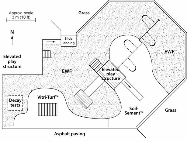
Figure 1—Schematic plan plan of playground site at Governor Nelson State Park playground site.
Preparation of Playground Subsurface and Drainage
Our efforts began by removing the existing sand surface to a depth of 0.38 m (15 in.) (Fig. 2). All roots, stones, and vege-tation were removed. Much of the tonnage of sand was moved by two skid-steer loaders, but significant amount required handwork by a dedicated and hardworking volunteer crew from the Waunakee Rotary and a local chapter of Telephone Pioneers of America. The work crew also included employees of the park, the Wisconsin Department of Natural Resources, and the Forest Service. The majority of the clean sand was used to replenish the adjacent beach at the park and the remainder was piled in a wooded site nearby. Approximately 12 h of equipment time and 48 h of personnel time were required to remove the sand.
Installation of Drainage Base
Following industry standard EWF installation practices, we ensured that the excavated surface had a minimum of 1% slope for drainage. A lightweight landscaping geotextile fabric was placed on the surface, followed by a 0.08-m (3-in.) layer of 18-mm (3/4-in.) washed, angular drainage rock (Fig. 3). Half the rock was placed using a skid-steer loader and the other half was placed manually using wheel-barrows. All the rock was shoveled and raked by hand to a uniform depth. Another layer of geotextile fabric was laid on top of the rock layer (Fig. 4). Handfuls of rock were thrown on the fabric to keep the wind from blowing it out of place. The layers of geotextile fabric kept soil and fiber from clogging the rock and thus preserved the drainage quality of the rock layer. Approximately 25 metric tons (28 tons) of rock was used. Placing the rock and geotextile required 25 h of manual labor and 3 h of skid-loader use.
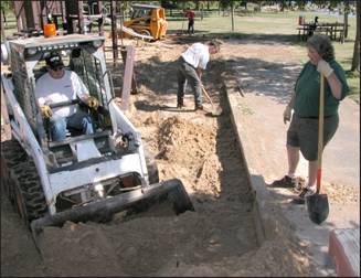
Figure 2—Removal of sand from existing playground surface.
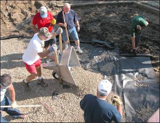
Figure 3 —Placement of drainage fabric and rock on playground subsurface.
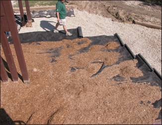
Figure 4— Completion of drainage system; second layer of fabric laid over drainage rock.
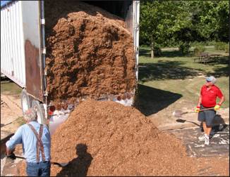
Figure 5—Application of engineered wood fiber (EWF).
EWF Application
Fifty cubic meters (66 yd3) of EWF, donated by a cooperator (Zeager Bros. Inc.), was obtained from BNB Bedding of Oskaloosa, Iowa, and delivered in a 75-m3 (100-yd3) live-bottom trailer (Fig. 5). The EWF was manually applied to a thickness of 0.3 m (12 in.). One week later, after the surface had been further compacted by usage, approximately 40 m3 (53 yd3) of EWF was added and compacted to return the surface to the full depth of 0.3 m (12 in.).
Bonded Surface Installation
Two weeks after applying the EWF, we returned to stabilize the upper surface. Considering that children had used the playground in the meantime, we had hoped the EWF was adequately compacted to support the stabilized layer. Our plan was to treat approximately 30% of the playground with the two binding systems and to leave the remainder as the untreated control (Fig. 1). The two binder systems used to fabricate these systems were
1. an acrylic and polyvinyl acetate polymer emulsion, Soil-Sement (Midwest Industrial, Canton, Ohio), mixed 30% by dry weight of solids to unit weight of dry EWF and applied 63 mm (2.5 in.) thick, and
2. a non-foaming polyurethane (Vitricon), Vitri-Turf (Poly-mer Plastics Corp., Commack, New York), mixed 30% by weight to unit weight of dry EWF and applied 37 mm (1.5 in.) thick.
If the EWF has 20% moisture content, that weight should be subtracted from the EWF wei ght prior to calculating the weight addition of the binder. The same procedure should be followed for the binder that does not contain 100% solids. The weight percentage should be calculated only on the solids content of the binder. Because the EWF was installed in the fall, we monitored the air temperature; both stabilizing binders required 4°C (40°degrees F) for proper curing. On the date of installation, the overnight temperatures had dipped to - 2°C (28°deg. F) . The crew waited for the temperature to rise before mixing the EWF with the binders, which had been stored at room temperature. When the EWF was mixed with the bind-ers, the temperature of the resultant mixture was well above 10°C (50°degrees F ).
A portion of EWF was removed from the play area for stabilization. For the polyurethane binder, 38 mm (1-1/2 in.) of EWF was removed and for the emulsion polymer, 64 mm (2-1/2 in.) of EWF. The EWF was placed in a 160-L (40-gal) portable mortar mixer (Fig. 6). The amount of binder added was determined as a proportion (30%) of EWF dry weight (volumetrically equivalent to 0.041 m3, 1.45 ft3) to 5.3 L (1.25 gal) of Vitri-Turf or 10.6 L (2.5 gal) of Soil-Sement. Weight proportion was 77:23. The EWF and binder were mixed for approximately 3 min. The mixture was transported by polyethylene tray wheelbarrows to the target pad and spread with hand tools to an even thickness (Fig. 7).
The area was then compacted and flattened with a 1.2-m by 1.2-m by 16-mm (4-ft by 4-ft by 5/8-in.) piece of plywood covered with a polyethylene release sheet. To compact the cushioning pad to the full 0.3-m (12-in.) depth required for unbonded EWF, a 90-kg (198-lb) person slowly stepped on the plywood in each quadrant, applying firm pressure.

Figure 6— Mixing of binder and EWF in mortar mixer.

Figure 7—Leveling and compacti ng the on of binder – / EWF mixture.
The two SEWF surfaces were allowed to cure or bond for 6 days prior to usage. The entire surface was covered with polyethylene sheeting for 3 days to protect it from rain. Within 2 h of placing the Vitri-Turf, the surface was some-what rigid to slight hand pressure. The Soil-Sement surface did not begin to cure or cross-link until more than 48 h had passed; when the polyethylene sheeting was removed, the surface was still slightly tacky. The area was left open to the air for another 3 days prior to opening the play surface for use. Figure 8 shows the completed surface, with little notable differences between the three surface materials.

Figure 8— Completed play ground area looking north: left, Vitri-Turf SEWF; right, Soil-Sement SEWF; top, EWF. Line of demarcation is below wheelchair footrest.

Figure 9— Measurement of accessibility with rotational penetrometer.
Test Procedures
Field Observation Reports
The playground site was not under direct supervision or observation by park staff or other responsible personnel. However, on-duty staff noted any public concerns and changes at the site. Forest Products Laboratory staff visited the site at least weekly for the first 2 months and at least monthly thereafter (if the ground was thawed) to perform the rotational penetrometer test and to observe and annotate any maintenance needs, use patterns, or other issues.
Accessibility Measures
All surfaces were measured with the rotational penetrometer periodically over the first 6 months of exposure (Fig. 9). This device subjects the surface to a low-speed rotational bearing test that simulates the weight and action of a front caster wheel on a wheelchair. The procedures are based on a draft national standard test method for the firmness and stability of ground and floor surfaces (RESNA 2000), which uses an average of five readings. This test provides objective meas-ures of surface firmness and stability and has been correlated to the work measurement of ASTM F1951, “Accessibility of Surface Systems,” for a wide array of surfacing and floor coverings (ASTM 1999b). The RESNA test was performed 1 week after surface installation and as often as once a week in the first 2 months, using the rotational penetrometer and protocol for assessing bearing/ rotational surface indentation (Axelson and Chesney 1999). The device was used on test areas selected as representative of the entire surface.
Impact Attenuation Tests
Impact tests were performed by a cooperator (Zeager Bros. Inc.) 7 weeks after EWF installation. ASTM F1292–99 test methods were used at a constant test drop height of 3.05 m (10 ft) (Fig. 10). Maximum g levels and head injury criteria (HIC) were measured.

Figure 10—Impact test setup for drop height **of 3.05 m (10 ft).**

Figure 11— Biodeterioration samples on EWF surface.
Moisture and Durability
To learn more about biodeterioration of the EWF playground system, we sampled and ovendried packets of EWF material and buried them in the unsurfaced portion of the playground. Polyolefin geotextile fiber pouches were each filled with approximately 40 oven-dry grams of fiber (Fig. 11). These biodeterioration samples were placed so as to allow circulation of water and air. The EWF surface was excavated throughout its entire 0.3-m (12-in.) depth to determine the moisture profile of the surfacing system. The samples were buried at depths of 100, 150, 200, 250, and 300 mm (4, 6, 8, 10 and 12 in.) (Fig. 11). One-quarter of the samples was removed at 6 months to provide data on wood fiber moisture content and weight loss. After drying and weighing, the removed packets were reinserted and the area was restored.