
Bonded Impact/cushioning Surfaces
Eight different surface test specimens were formed with surface dimensions of 1.2m x 1.2m with a depth of 0.3m (48”x48”x 12”) in Madison WI (Figure 1). Seven had a top layer of bonded resin/EWF and the eighth was a full-depth EWF control. Two additional surfaces were made (Figure 1, A1 and E1) and each were duplicates of other surfacing test areas. A1 and E1 were on a slope to assure drainage of the entire test surface. All surfaces used Engineered Wood Fiber (EWF), as defined by ASTM F2075-01. All surfaced specimens were compacted to simulate the finished surface of a play area. Given that there is no industry, governmental, or association definition or standard for compacting EWF, we followed playground industry installation practices.
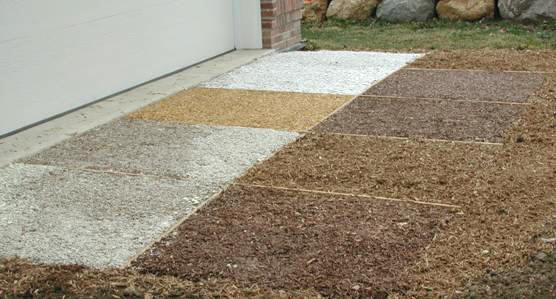
Figure 1. Overview of the test surfaces in Madison, Wisconsin. From top left along the concrete edge the test surfaces are A1, A2, B, C, D; then from top right toward the bottom, E1, F, G, E2, H (Note: A1 and E1 were not useable due to slope in excess of 5%).
Table 1: Summary of Surfaces Evaluated in Phase II Testing.
| Surface ID | Matrix Adhesive | Top Surface Thickness |
| A2 | 35% Silicone | 50 mm (2”) |
| B | 40% Silicone | 38 mm (1 ½”) |
| C | 30% Polyurethane | 38 mm (1 ½”) |
| D | 30% Polyurethane | 25 mm (1”) over geotextile |
| E2 | None | None |
| F | 30% Latex | 63 mm (2 ½”) |
| G | 25% Latex | 50 mm (2”) over geotextile |
| H | 30% Vitriturf | 38 mm (1 ½”) |
All Phase II surfaces (Table 1) were selected based on an evaluation of Phase I results. Any Phase I system which was shown to have either undesirable surface stability or resiliency was eliminated from Phase II testing. All Phase II surfaces were fabricated from EWF matched to Phase I materials and obtained from a commercial supplier (Zeager Bros. Obtained from their Oskaloosa, Iowa licensee.). A baseline “control” test surface was also made with only EWF.
Four bonding systems were used to fabricate these surfaces.These systems* are:
a) silicone-based, Dow-Corning AllGuard, a waterproofing coating,
b) a synthetic latex, Midwest Industrial Soil-Sement
c) a foaming polyurethane (Franklin ReacTITE 8143), and
d) a non-foaming polyurethane (Vitricon’s) Vitriturf
- Tradenames used only for the reader’s information and do not constitute an endorsement by USDA Forest Service.
One interfacial treatment was used for two of the surfaced specimens. A 1.2 m x 1.2 m (48 in. x 48 in.) single ply layer of lightweight polyolefin landscaping geotextile was placed between the unbonded and bonded layers of these specimens. The geotextile was intended to provide cotinuity for the thinner bonded surface layers in the event that they might fracture through the entire thickness. When this happens the layer could be ejected from its original position and become a hazard on the remaining bonded surface.
Installation of Test Surfaces
In accordance with standard EWF design and construction practice (Figure 2), the full depth surfaces were prepared to the same requirements needed for permanent playground surfaces. Our installation began on February 27, 2002 and was completed with bonded top surfaces within six weeks. The installation steps were:
1)Excavate area 380 mm (15 in.) in depth with a minimum of 1% grade to ensure proper drainage. All roots, stones, and vegetation were removed.
2)Place a diversion along the slope above the test area to assure no direct site drainage into the surfaced area.
3)Cover entire subgrade with one layer of geotextile. Overlap courses of geotextile by 125 mm (5 in.).
4)Cover the excavated surface to a 75 mm (3 in.) depth of washed 18 mm (¾-inch) stone.
5)Cover entire drainage bed with one layer of geotextile. Overlap courses of geotextile by 5 inches.
6)Spread wood fiber to a depth of 1.5 times the target depth.
7)Hand rake for a smooth finished surface.
8)Install retaining borders (15 mm thick x 100 mm wide plywood) between each pad.
9)Top Surface Preparation and Installation: (Assure temperatures are correct for this operation. Most stabilizing binders required 40 degrees F. for proper curing.)
a)Place the EWF to be stabilized into 60 liter (15 gallon) mixing bin. Measure the needed material by volume (1.5x the volume needed).
b)Measure EWF moisture content.
c)Measure the binder as a proportion of EWF dry weight.
d)Mix the EWF and binder using a mixing paddle.
e) If required, place the single layer of geotextile onto the EWF.
f)Immediately dump the resin/EWF mixture onto the target pad, spread with hand tools to even thickness and flatten with a 1.2 m x 1.2 m x 16 mm (4 ft. x 4 ft. x 5/8-inch) piece of plywood using firm pressure to bring the cushioning pad thickness to the full 0.3 m (12 in.) depth required for unbonded EWF.
Figure 2. Representational cross-section of the installed surfaces. Note that the EWF thickness includes the thickness of any stabilized EWF layer.
Test Procedures
Accessibility Measures
Periodically over the 6-month exposure and again following the 6-month impact tests, all surfaced specimens were subjected to a low-speed rotational bearing test meant to simulate the weight and action of a front caster wheel on a wheelchair. This test provides quantitative measures of firmness and stability of the surfaces. It has been correlated to the work measurement done in ASTM F1951, Accessibility of Surface Systems, for a wide array of surfacing and floor coverings. This test was performed one week after surface installation and each month thereafter using the Beneficial Designs’ rotational penetrometer and protocol for assessing the bearing/rotational indentation on each surface (Axelson and Chesney, 1999). Each of the seven tests was completed at a unique location around the periphery of the surface.
Impact Attenuation Tests
One set of impact tests were run during this study. This test was completed after the surfaces had been exposed for six months. ASTM F 1292-99 test specifications and F355-95 test methods were used at a constant test drop height of 3.05m (10.0 feet). Each specimen had only three impact tests run in sequence per the specification. Per ASTM F355, the instrumented headform was mounted on a magnetic release over the center of the surface. The first impact was ignored and data collected from the second and third impact test. Samples of EWF will be obtained from each surface for moisture content determination immediately following the impact testing.
Moisture and Durability:
The field systems were installed and exposed outdoors for a minimum of a 6-month period. The intent was to expose these surfaces to a wide range of climatic conditions, freeze-thaw cycles, spring rains and summer heat. The ability of the mat to drain water from its surface and interior was important to reduce biodeterioration and maintain cushioning behavior during freezing temperatures. Evaluation of the surface and the entire mat’s permeability was subjective. Following the 6-month exposure period, we sampled the surface layer and the EWF just below the bonded surface. These samples provide data on wood fiber moisture content and density after 6-months of field exposure. One EWF surface was excavated down through its entire 0.3 m (12 in.) depth to determine the moisture profile of the entire Resin-EWF system. This same surface also had a 50mm (2”) diameter observation pipe so that ground water in the site could be monitored.