
V401 General
V401.1 Scope
The provisions of Chapter 4 shall apply where required by Chapter 2 or where referenced by a requirement in this document.
V402 Components
V402.1 Accessible Routes
Onboard accessible routes shall consist of one or more of the following components:
- walking surfaces with a running slope not steeper than 1:20 complying with V403,
- doors, doorways, and gates complying with V404,
- ramps complying with V405,
- curb ramps complying with V406,
- elevators complying with V407,
- elevators, where permitted by V206.6, complying with 408, and
- platform lifts, where permitted by V206.7, complying with V409.
V402.2 Accessible Passenger Boarding Systems
Accessible passenger boarding systems shall consist of one or more of the following components:
- walking surfaces with a running slope not steeper than 1:20 complying with V403;
- doors and doorways complying with V404;
- ramps complying with V405;
- elevators complying with V407 or V408;
- platform lifts complying with V409;
- gangways complying with V410; and
- manually powered boarding lifts complying with V411.
V403 Walking Surfaces
V403.1 General
Walking surfaces with running slopes not steeper than1:20 shall comply with V403. Walking surfaces on vehicle decks shall be permitted to overlap vehicle ways.
V403.2 Deck Surface
Deck surfaces shall comply with V302.
V403.3 Slope
The running slope of walking surfaces shall not be steeper than 1:20. The cross slope of walking surfaces shall not be steeper than 1:48.
V403.4 Changes in Level
Changes in level shall comply with V303.
V403.5 Clearances
Walking surfaces shall provide clearances complying with V403.5.
V403.5.1 Clear Width
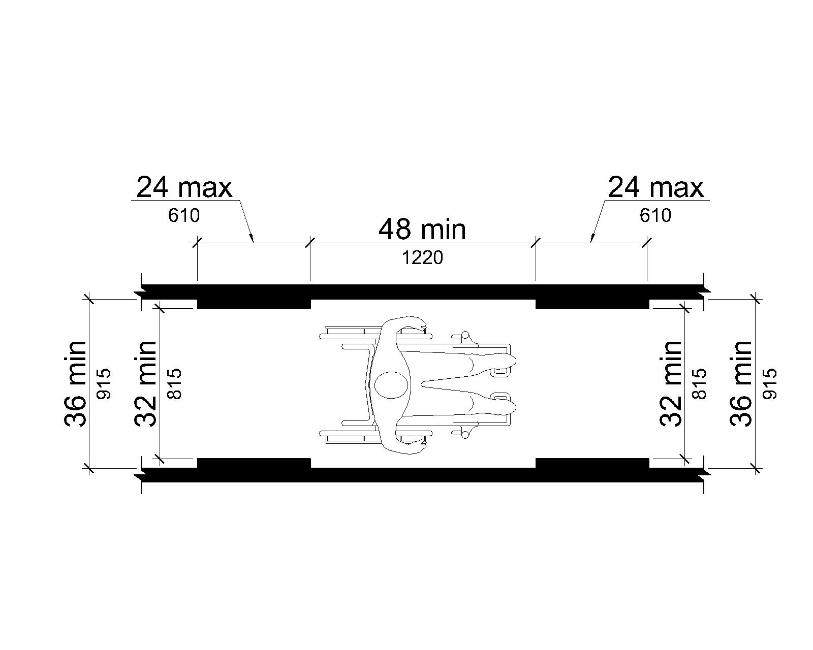
Except as provided in V403.5.2 and V403.5.3, the clear width of walking surfaces shall be 36 inches (915 mm) minimum.
EXCEPTIONS
- The clear width shall be permitted to be reduced to 32 inches (815 mm) minimum for a length of 24 inches (610 mm) maximum, if reduced width segments are separated by segments that are 48 inches (1220 mm) long minimum and 36 inches (915 mm) wide minimum.
- Where the largest deck is less than 3,000 square feet (279 m²), the walking surface shall be permitted to have a clear width of 32 inches (815 mm) minimum.
- Where the largest deck is less than 3,000 square feet (279 m²), fold-down seats complying with V309 shall be permitted to project into walking surface clearances when in the down position.
Advisory V403.5.1 Clear Width Exception 3. Although the exception allows fold-down seats to project into walking surfaces, the administrative authority may not allow such projections or may limit the amount of projection if the walking surface subject to this document is also part of a means of escape required by the administrative authority.
V403.5.2 Clear Width at Turn.
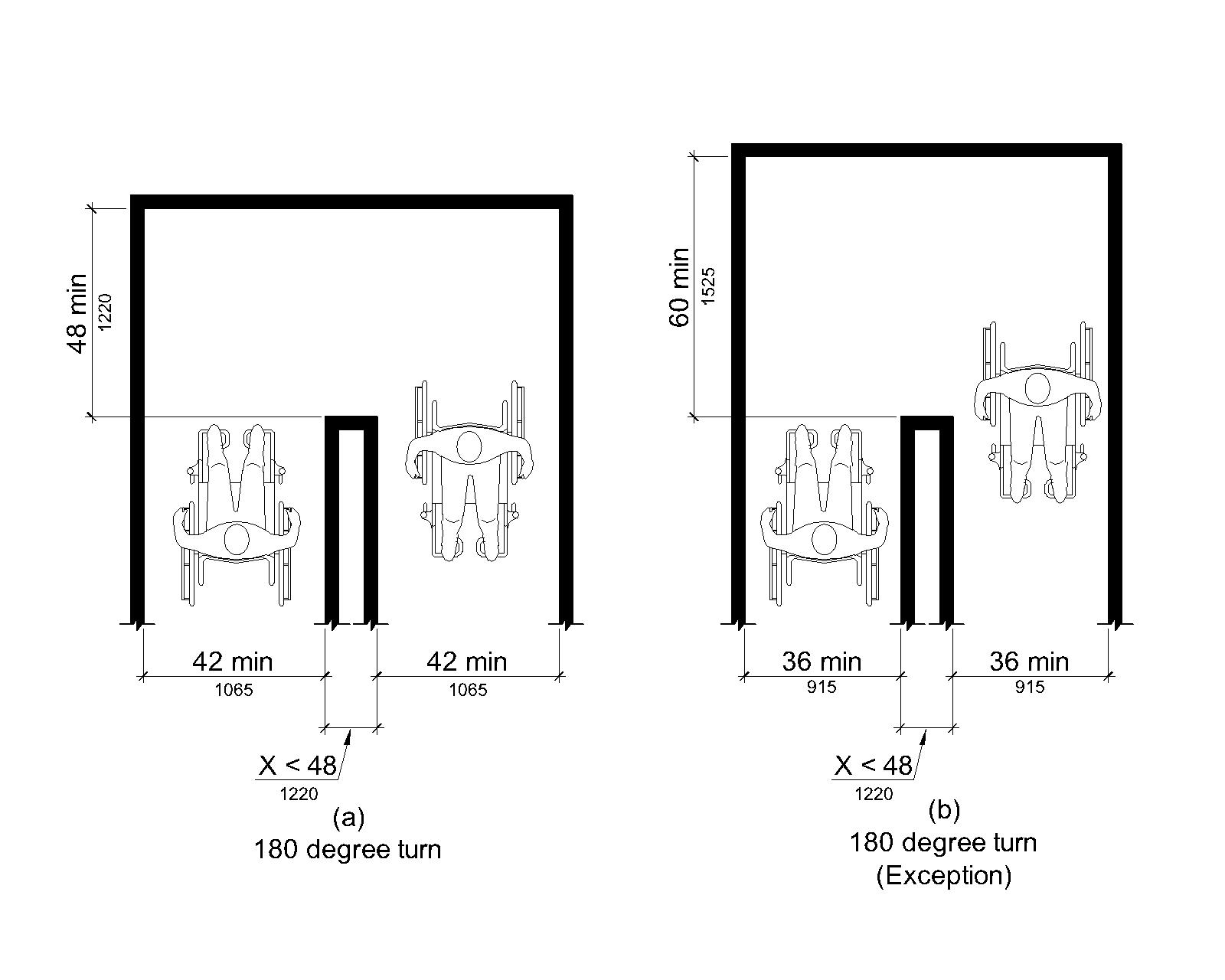
V403.5.2.1 Clear Width at 180 Degree Turn
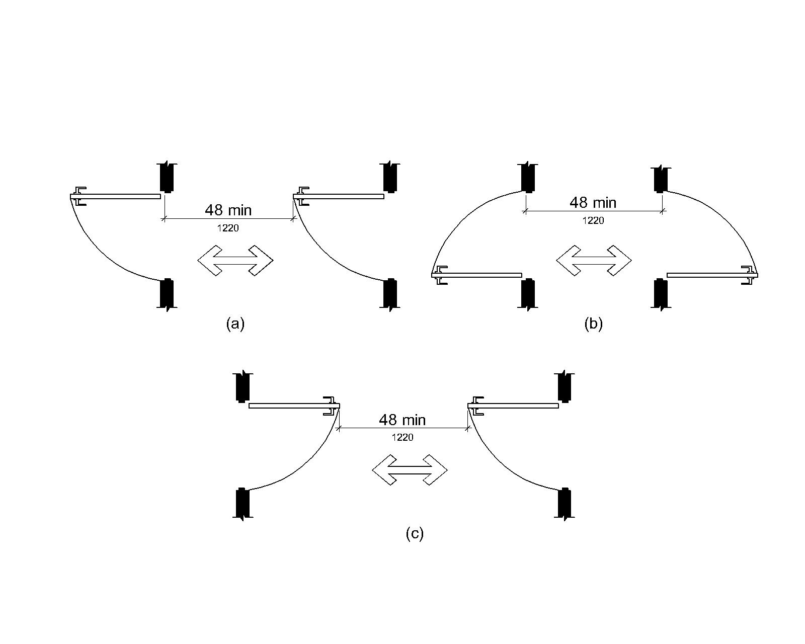
Where the walking surface makes a 180 degree turn around an element which is less than 48 inches (1220 mm) wide, clear width shall be 42 inches (1065 mm) minimum approaching the turn, 48 inches (1220 mm) minimum at the turn and 42 inches (1065 mm) minimum leaving the turn.
EXCEPTION
Where the clear width at the turn is 60 inches (1525 mm) minimum,V403.5.2.1 shall not apply.
V403.5.2.2 Clear Width at 90 Degree Turn
Where the walking surface is less than 36 inches (915 mm) wide and makes a 90 degree turn, an L-shaped space shall be provided with one stroke 90 inches (2285 mm) minimum in length having a width of 32 inches (815 mm) minimum and the other stroke 56 inches (1420 mm) minimum in length having a width of 42 inches (1065 mm) minimum.
V403.5.3 Passing Spaces
A walking surface with a clear width less than 60 inches (1525 mm) shall provide passing spaces at intervals of 200 feet (61 m) maximum. Passing spaces shall be either: a space 60 inches (1525 mm) minimum by 60 inches (1525 mm) minimum; or, an intersection of two walking surfaces providing a T-shaped space complying with V304.3.2 where the base and arms of the T-shaped space extend 48 inches (1220 mm) minimum beyond the intersection.
V403.6 Handrails
Where handrails are provided along walking surfaces with running slopes not steeper than 1:20, handrails shall comply with V503.
V404 Doors, Doorways, and Gates
V404.1 General
Doors, doorways, and gates shall comply with V404.
EXCEPTION
Where doors, doorways, and gates are intended to be operated only by employees, they shall not be required to:
- Provide the portion of the maneuvering clearance beyond the latch side of the door specified in V404.2.4; or
- Comply with V404.2.7, V404.2.8, V404.2.9, V404.3.2 and V404.3.4 through V404.3.7.
Advisory V404.1 General Exception. Employees must have sole control of doors that are eligible for this exception. It would not be acceptable for employees to operate the doors for people with disabilities while allowing other passengers to have independent access.
V404.2 Manual Doors, Doorways, and Manual Gates
Manual doors and doorways and manual gates intended for user passage shall comply with V404.2.
V404.2.1 Revolving Doors, Gates, and Turnstiles
Revolving doors, revolving gates, and turnstiles shall not be part of an accessible route.
V404.2.2 Double-Leaf Doors and Gates
At least one of the active leaves of doorways with two leaves shall comply with V404.2.3 and V404.2.4.
EXCEPTION
At doorways intended to be operated only by employees at entry and departure points, and at vessel evacuation points, V404.2.2 shall not apply.
V404.2.3 Clear Width
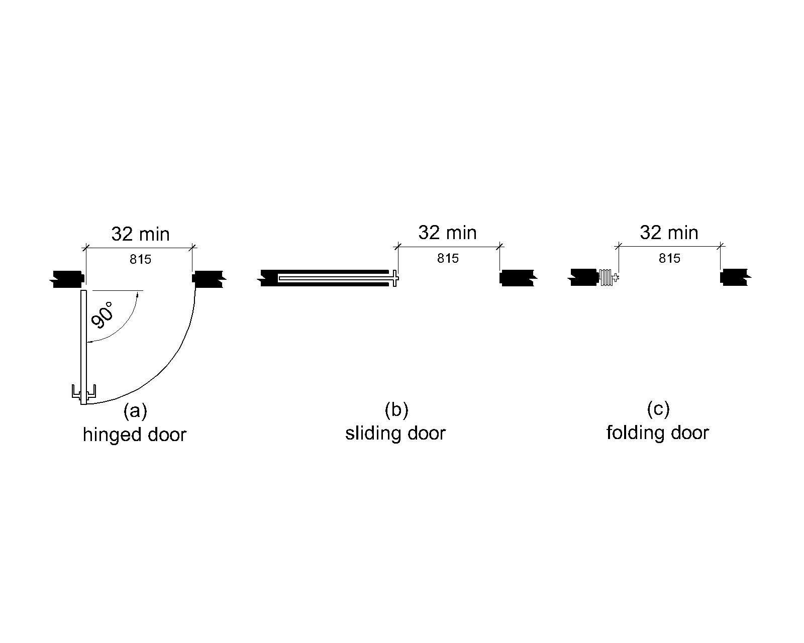
Door openings shall provide a clear width of 32 inches (815 mm) minimum. Clear openings of doorways with swinging doors shall be measured between the face of the door and the stop, with the door open 90 degrees. Openings more than 24 inches (610 mm) deep shall provide a clear opening of 36 inches (915 mm) minimum. There shall be no projections into the required clear opening width lower than 34 inches (865 mm) above the finish deck surface. Projections into the clear opening width between 34 inches (865 mm) and 80 inches (2030 mm) above the finish deck surface shall not exceed 4 inches (100 mm).
EXCEPTIONS
- In alterations, a projection of 5/8 inch (16 mm) maximum into the required clear width shall be permitted for the latch side stop.
- Door closers and door stops shall be permitted to be 78 inches (1980 mm) minimum above the finish deck surface.
- The clear width of doors to stairways shall be permitted to comply with the applicable requirements of the administrative authority.
Advisory V404.2.3 Clear Width. Where doors have radius corners, doors may have to be wider to provide a 32 inch (815 mm) minimum clear opening width at the bottom of the doors.
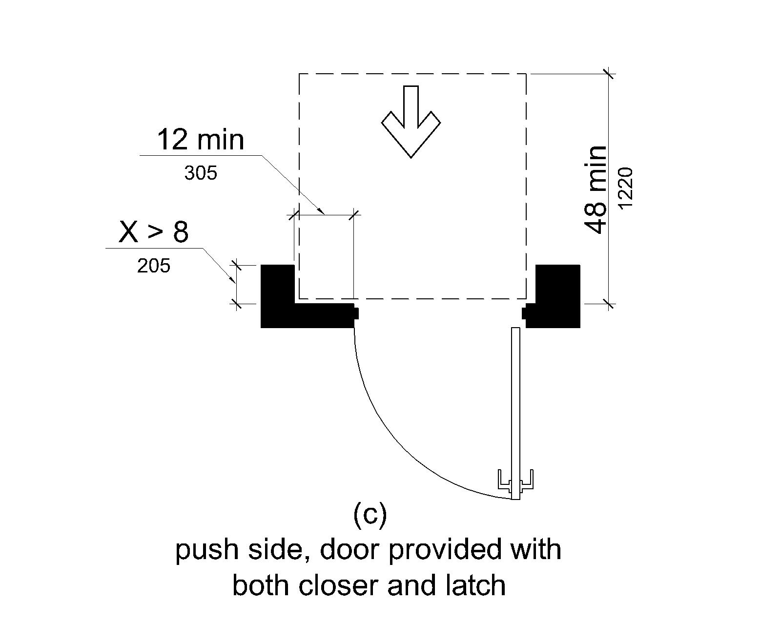
V404.2.4 Maneuvering Clearances
Minimum maneuvering clearances at doors and gates shall comply with V404.2.4. Maneuvering clearances shall extend the full width of the doorway and the required latch side or hinge side clearance.
EXCEPTIONS
- Entry doors to medical facility patient rooms shall not be required to provide the clearance beyond the latch side of the door.
- Maneuvering clearances shall not be required on the outboard side of doors and gates at entry and departure points that are required to be accessible.
- Where the largest deck is less than 3,000 square feet (279 m²), fold-down seats when in the down position shall be permitted to project into maneuvering clearances for doors and gates intended to be operated only by employees.
V404.2.4.1 Swinging Doors and Gates
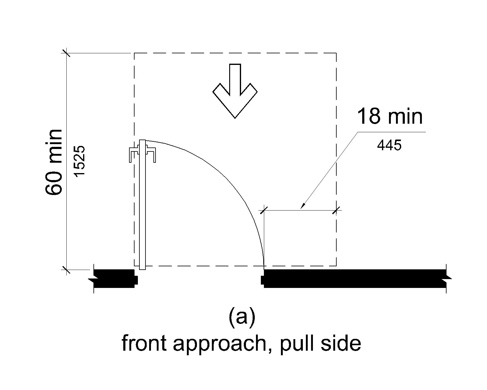
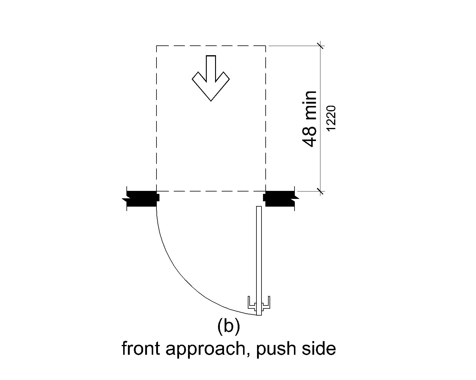
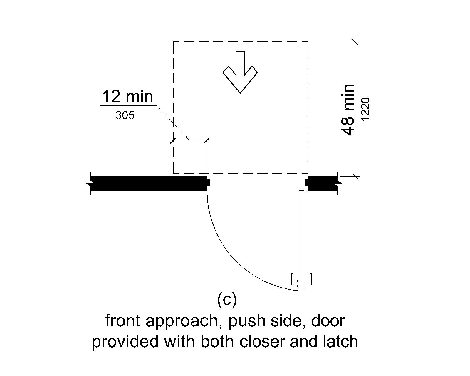
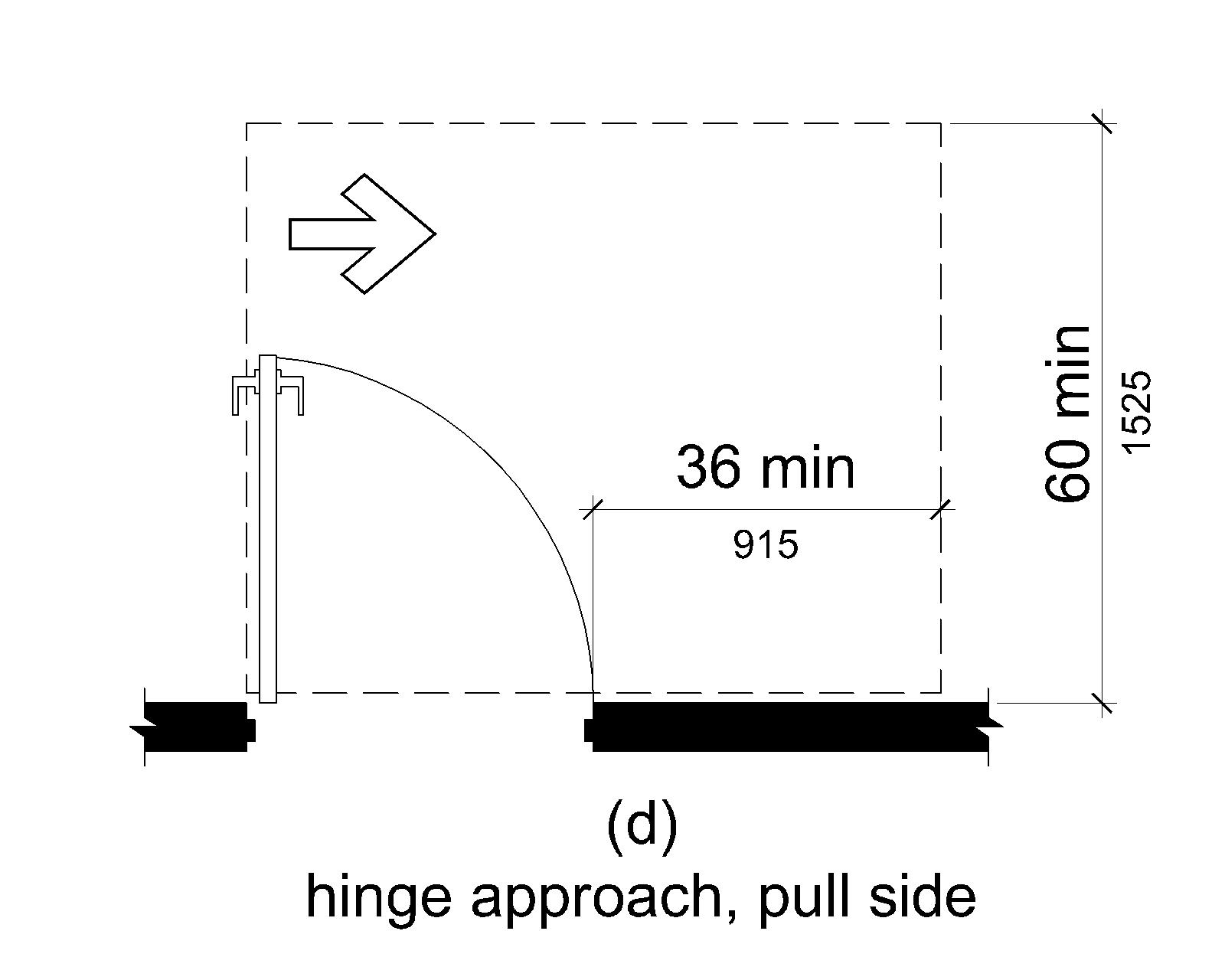
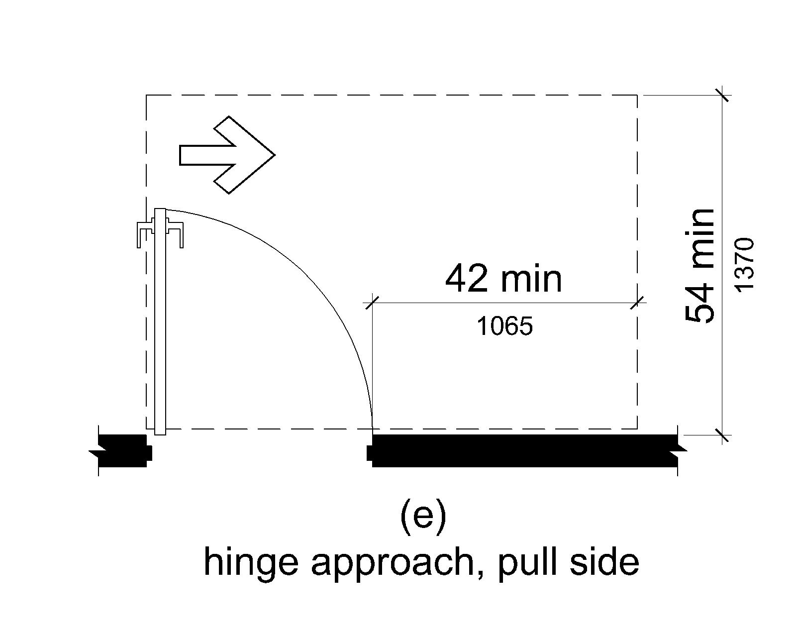
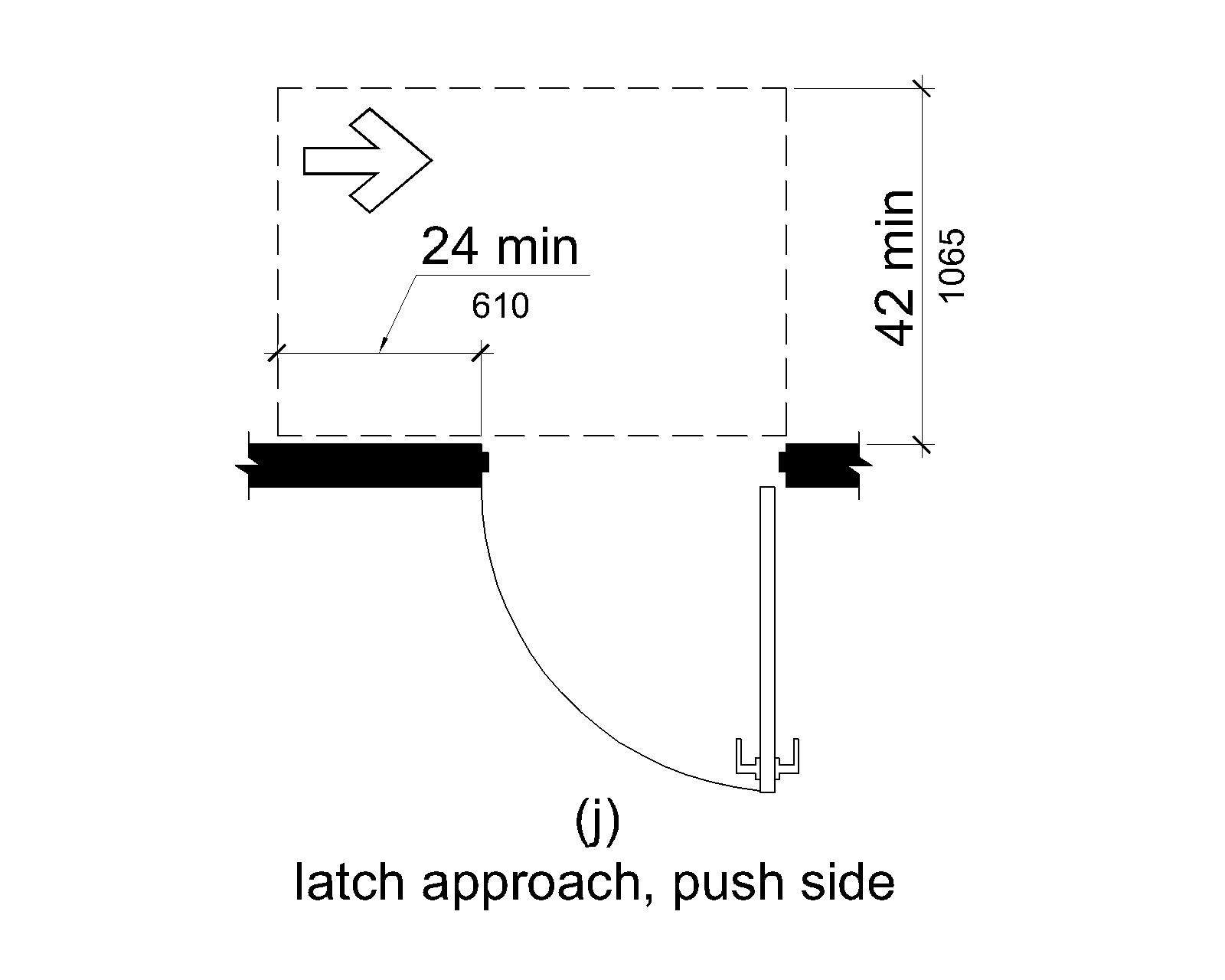
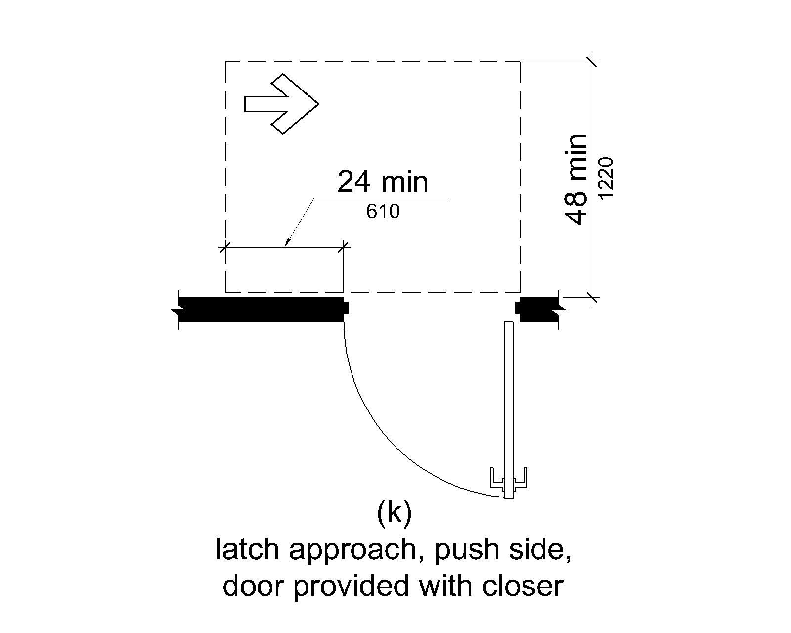
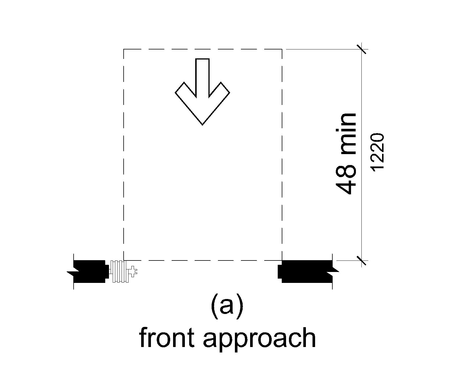
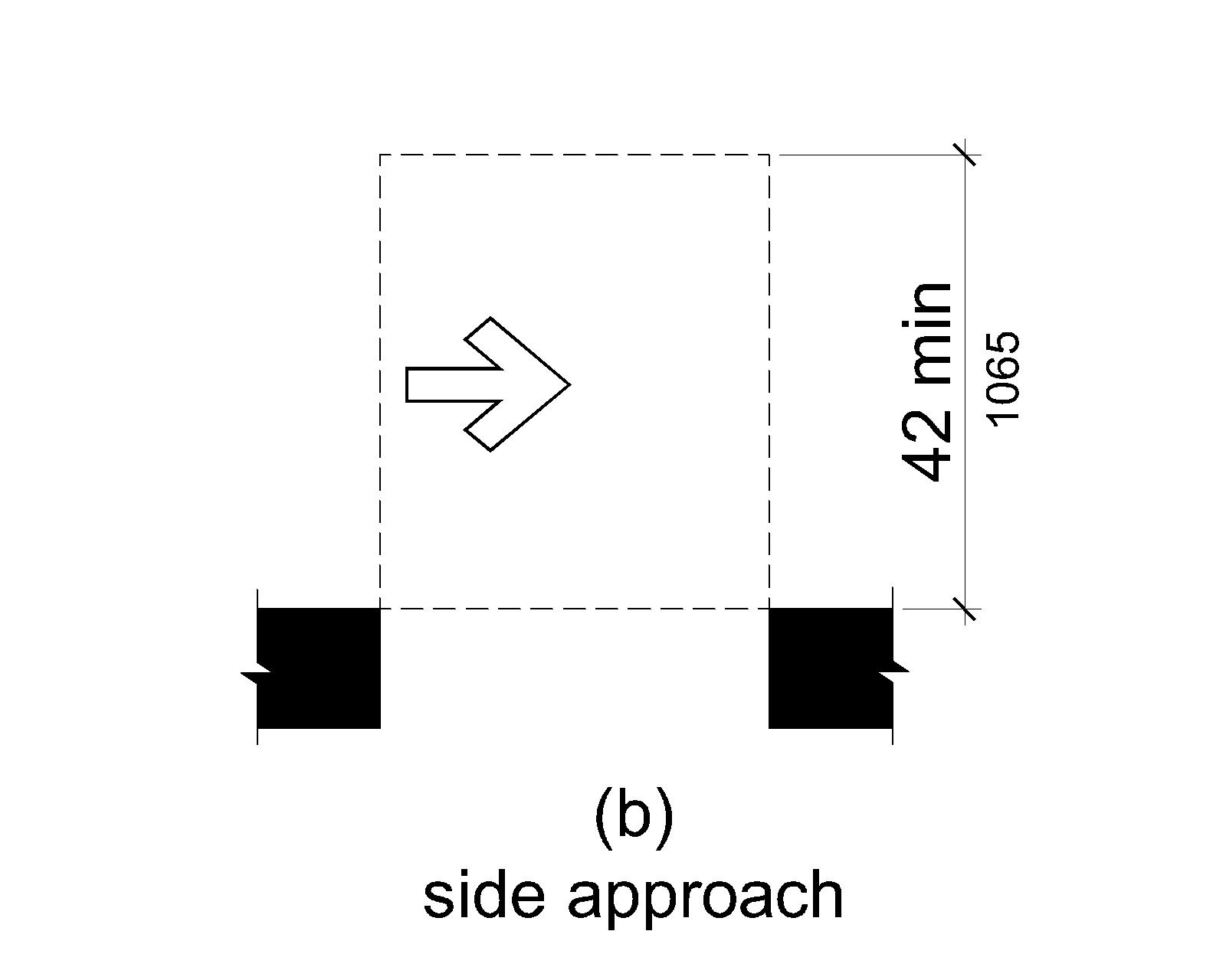
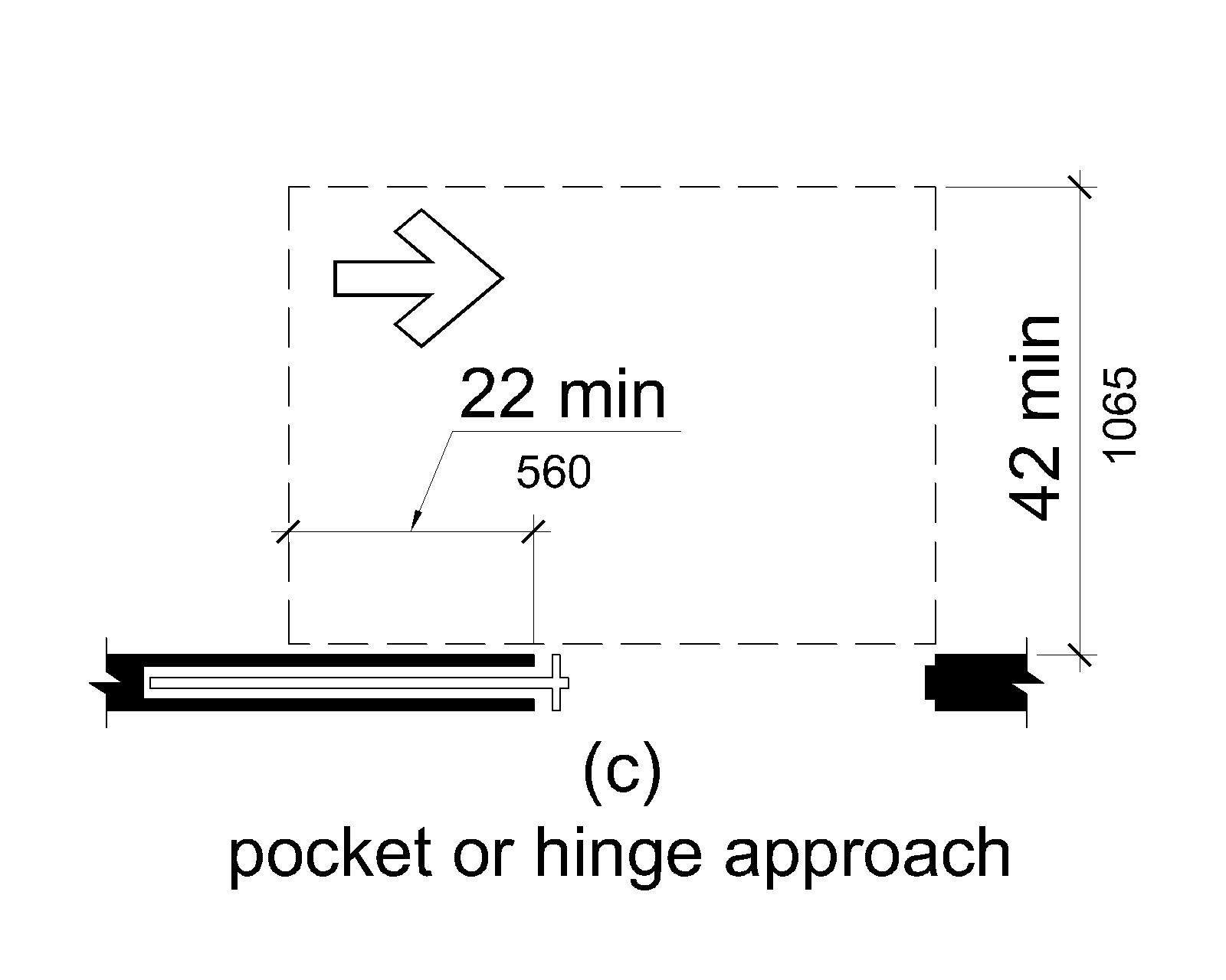
Swinging doors and gates shall have maneuvering clearances complying with Table V404.2.4.1.
| Types of Use | Minimum Maneuvering Clearance | ||
|---|---|---|---|
| Approach Direction | Door or Gate Side | Perpendicular to Doorway | Parallel to Doorway (beyond latch side unless noted) |
| From front | Pull | 60 inches (1525 mm) | 18 inches (455 mm) |
| From front | Push | 48 inches (1220 mm) | 0 inches (0 mm)1 |
| From hinge side | Pull | 60 inches (1525 mm) | 36 inches (915 mm) |
| From hinge side | Pull | 54 inches (1370 mm) | 42 inches (1065 mm) |
| From hinge side | Push | 42 inches (1065 mm)2 | 22 inches (560 mm)3 |
| From latch side | Pull | 48 inches (1220 mm)4 | 24 inches (610 mm) |
| From latch side | Push | 42 inches (1065 mm)4 | 24 inches (610 mm) |
Table Legend:
- Add 12 inches (305 mm) if closer and latch are provided.
- Add 6 inches (150 mm) if closer and latch are provided.
- Beyond hinge side.
- Add 6 inches (150 mm) if closer is provided.
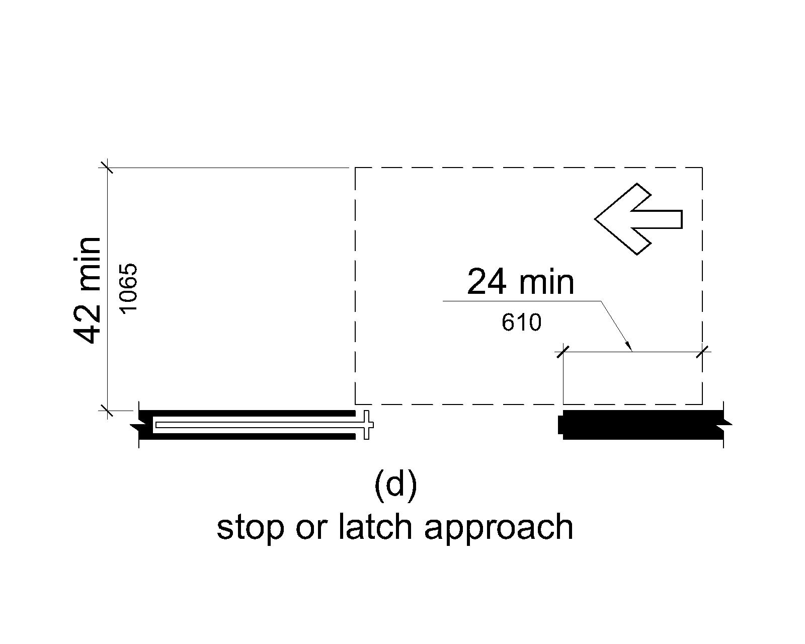
V404.2.4.2 Doorways without Doors or Gates, Sliding Doors, and Folding Doors
Doorways less than 36 inches (915 mm) wide without doors or gates, sliding doors, or folding doors shall have maneuvering clearances complying with Table V404.2.4.2.
| Minimum Maneuvering Clearance | ||
|---|---|---|
| Approach Direction | Perpendicular to Doorway | Parallel to Doorway (beyond stop/latch side unless noted) |
| From front | 48 inches (1220 mm) | 0 inches (0 mm) |
| From side1 | 42 inches (1065 mm) | 0 inches (0 mm) |
| From pocket/hinge side | 42 inches (1065 mm) | 22 inches (560 mm)2 |
| From stop/latch side | 42 inches (1065 mm) | 24 inches (610 mm) |
Table Legend:
- Doorway with no door only.
- Beyond pocket/hinge side.
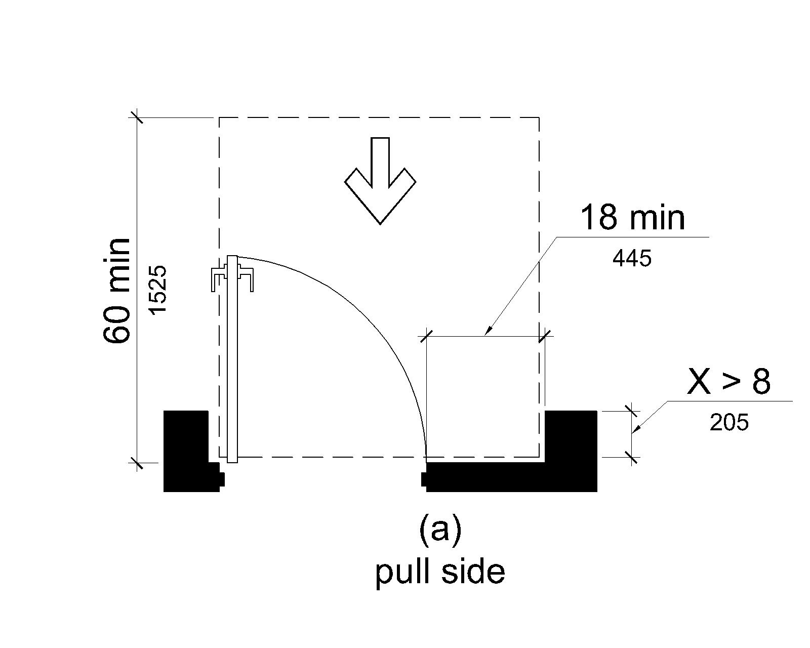
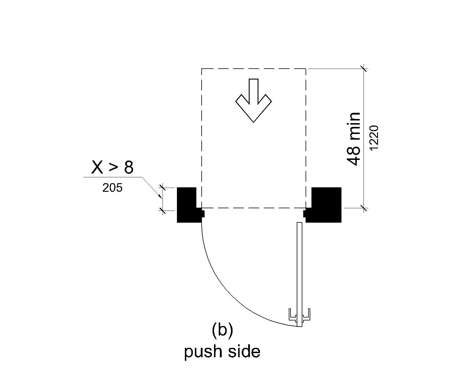
V404.2.4.3 Recessed Doors and Gates
Maneuvering clearances for forward approach shall be provided when any obstruction within 18 inches (455 mm) of the latch side of a doorway projects more than 8 inches (205 mm) beyond the face of the door, measured perpendicular to the face of the door or gate.
Advisory V404.2.4.3 Recessed Doors and Gates. A door can be recessed due to placement of casework, and other fixed elements adjacent to the doorway. This provision must be applied wherever doors are recessed.
V404.2.4.4 Deck Surface
Deck surface within required maneuvering clearances shall comply with V302. Changes in level are not permitted.
EXCEPTIONS
- Slopes not steeper than 1:48 shall be permitted.
- Changes in level at thresholds and coamings complying with V404.2.5 shall be permitted.
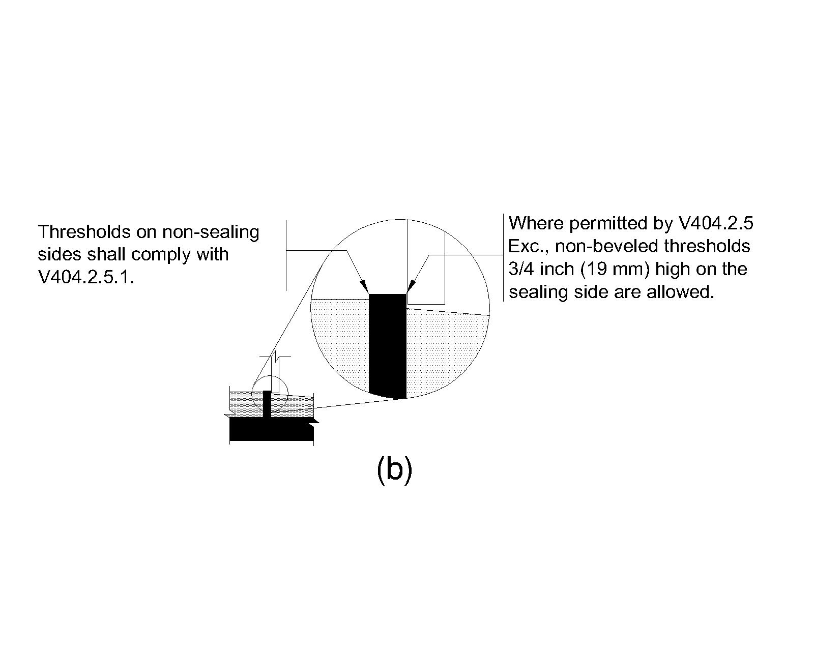
V404.2.5 Thresholds and Coamings
Doorways without coamings shall comply with V404.2.5.1. Doorways with coamings shall comply with V404.2.5.2.
EXCEPTION
Where required by the administrative authority to meet weathertight door sealing requirements, weathertight doors shall be permitted to have non-beveled thresholds ¾ inch (19 mm) high maximum on the sealing side of the doors provided that the thresholds contrast visually with adjacent deck surfaces either light-on-dark or dark-on-light.
Advisory V404.2.5 Exception. This exception can be used at doorways without coamings, and doorways with coamings where single ramp access complying with V404.2.5.2.1 or double ramp access and automatic doors complying with V404.2.5.2.2 are provided. Before using this exception at doorways with coamings where single ramp access or double ramp access and automatic doors are provided, it is recommended that alternatives be explored with the administrative authority such as installing drainage systems where weathertight doors seal against the top of ramp surfaces.
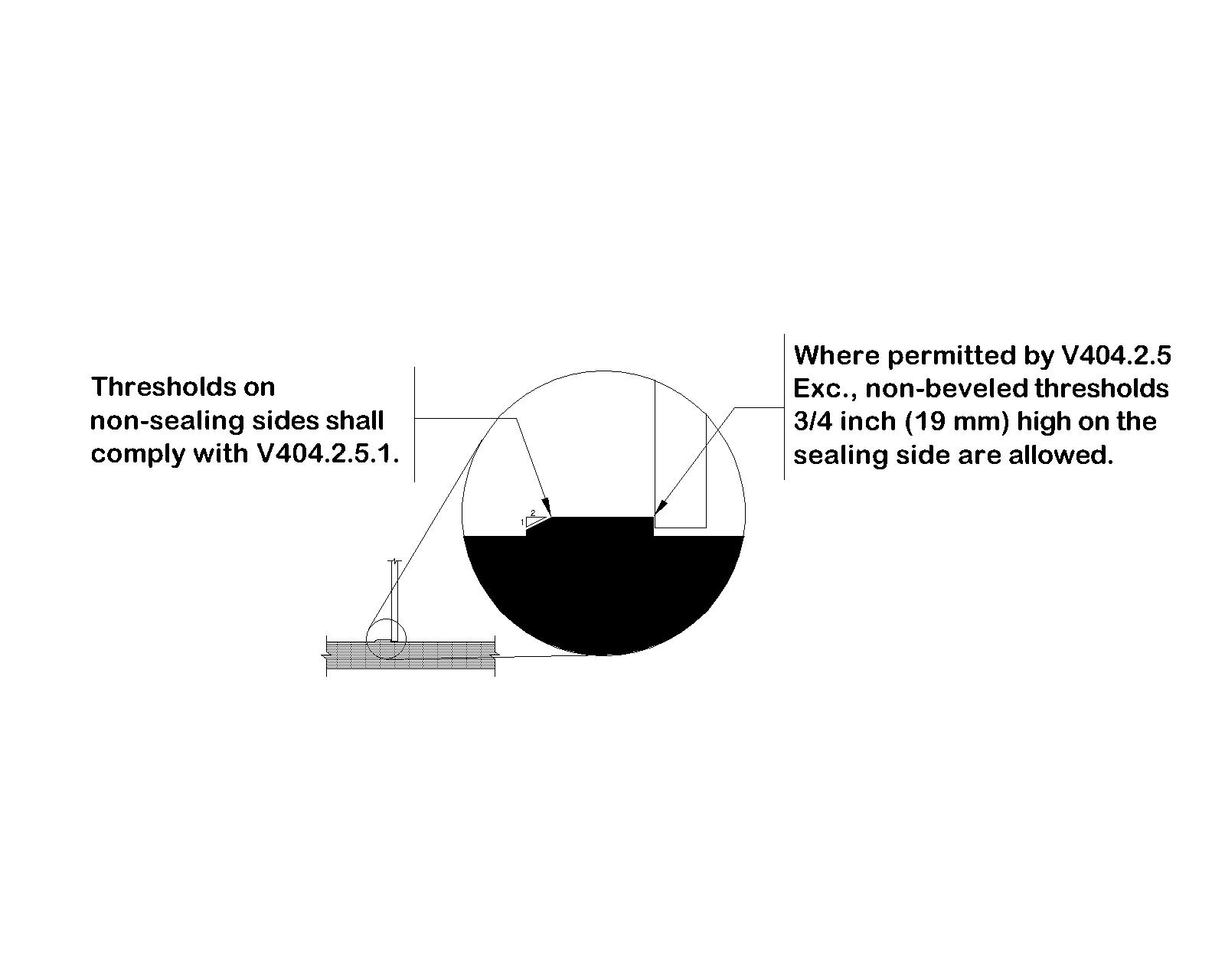
V404.2.5.1 Doorways without Coamings
Where provided at doorways without coamings, thresholds shall be ½ inch (13 mm) high maximum. Raised thresholds and changes in level at doorways shall comply with V302 and V303.
EXCEPTION
Existing or altered thresholds ¾ inch (19 mm) high maximum that have a beveled edge on each side with a slope not steeper than 1:2 shall not be required to comply with V404.2.5.1.
V404.2.5.2 Doorways with Coamings
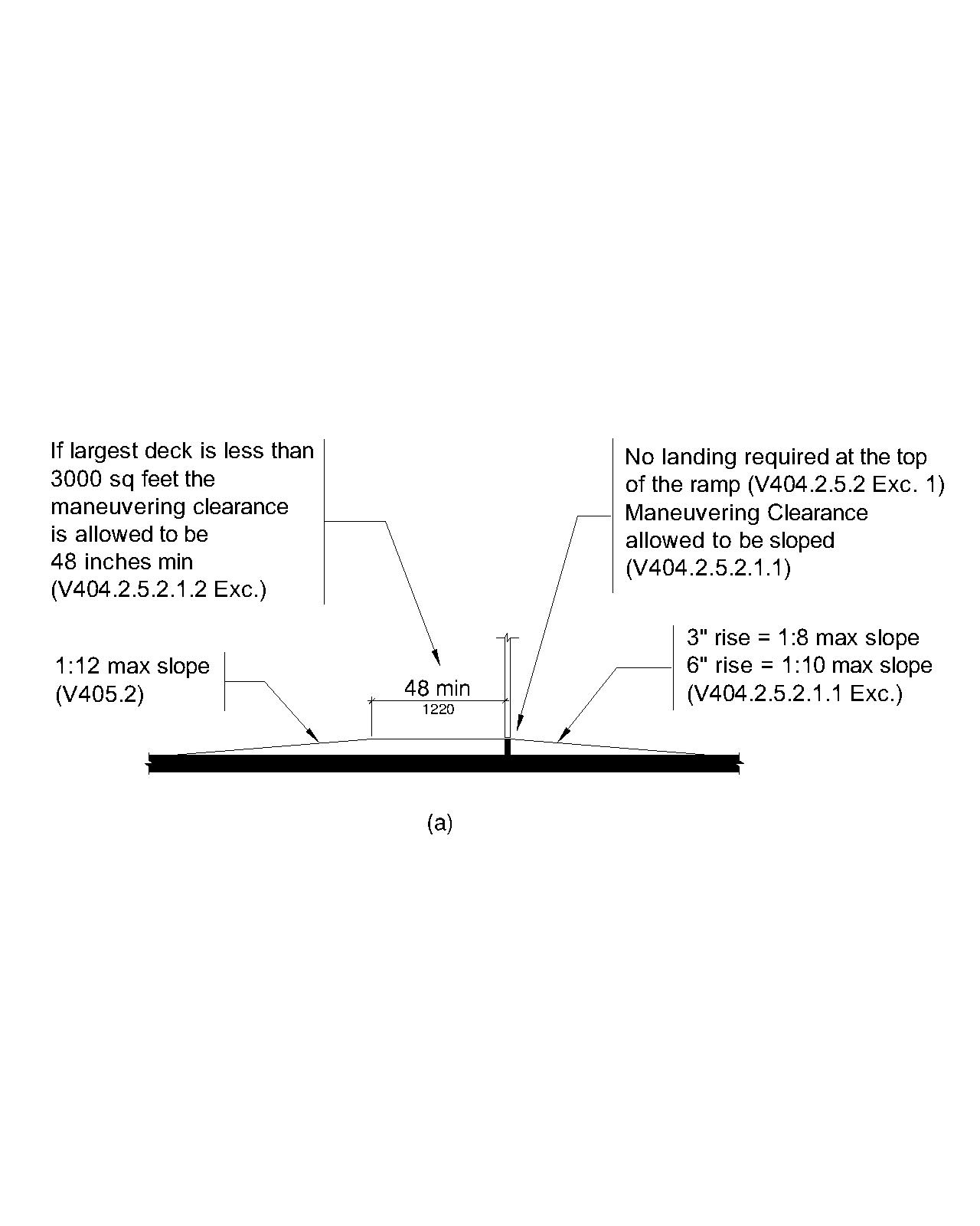
Where the administrative authority requires doorways to have coamings, the coaming shall conform to the minimum coaming height determined by the administrative authority and the doorways shall comply with V404.2.5.2.1 or with V404.2.5.2.2.
EXCEPTIONS
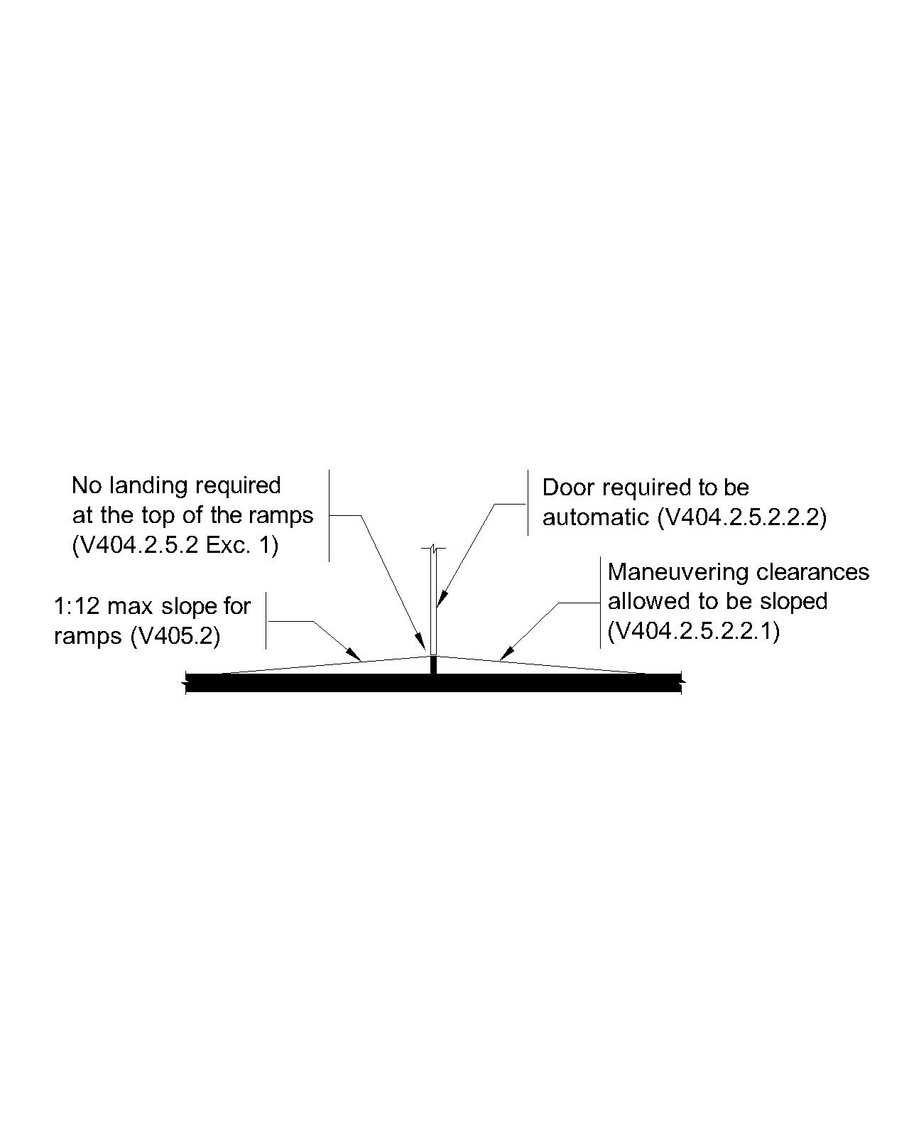
- Where ramps are provided at doorways with coamings, the landing at the top of the ramps specified in V405.7 shall not be required.
- Where the administrative authority permits coamings to be removable, doorways shall not be required to comply with V404.2.5.2 provided that: (a) the thresholds are readily removable by employees; (b) the doors are only employee operated; and (c) the weather deck areas accessed by the doors are not open to passengers when the vessel is underway, except in emergencies.
- Where the administrative authority determines that it is not feasible to comply with V404.2.5.2 due to space limitations and watertight doors are provided instead of weathertight doors, the thresholds on the side of the watertight doors containing the door seal are permitted to have non-beveled thresholds 1¼ inches (32 mm) high maximum provided that the thresholds contrast visually with adjacent deck surfaces either light-on-dark or dark-on-light.
V404.2.5.2.1 Single Ramp Access
Doorways with coamings shall provide single ramp access complying with V404.2.5.2.1.
V404.2.5.2.1.1 Side with Ramp
A ramp complying with V405 shall be provided on the side of the doorway to be protected from water infiltration. The ramp width shall be equal to or greater than the width of the maneuvering clearances required by V404.2.2.4.
EXCEPTION
Where the largest deck is less than 3,000 square feet (279 m²), the slope of the ramp run at doorways with coamings that provide single ramp access shall be permitted to comply with Table V405.2.
V404.2.5.2.1.2 Side without Ramp
On the side of the doorway without a ramp, changes in level are not permitted within the maneuvering clearances required by V404.2.2.4.
EXCEPTION
Where the largest deck is less than 3,000 square feet (279 m²), maneuvering clearances specified in V404.2.4 shall be permitted to be 48 inches (1220 mm) minimum in depth on the side of the doorway without a ramp.
V404.2.5.2.2 Double Ramp Access and Automatic Doors
Doorways with coamings shall provide double ramp access and automatic doors complying with V404.2.5.2.2.
V404.2.5.2.2.1 Double Ramps
Ramps complying with V405 shall be provided on each side of the doorway. The ramp width shall be equal to or greater than the width of the maneuvering clearances required by V404.2.2.4.
V404.2.5.2.2.2 Automatic Doors
Automatic doors complying with V404.3 shall be provided at doorways with double ramp access at coamings.
EXCEPTION
Where the doors are intended to be operated only by employees, the doors shall not be required to be automatic.
V404.2.6 Doors in Series and Gates in Series
The distance between two hinged or pivoted doors in series and gates in series shall be 48 inches (1220 mm) minimum plus the width of doors or gates swinging into the space.
V404.2.7 Door and Gate Hardware
Handles, pulls, latches, locks, and other operable parts on doors and gates shall comply with V309.4. Operable parts of such hardware shall be 34 inches (865 mm) minimum and 48 inches (1220 mm) maximum above the finish deck surface. Where sliding doors are in the fully open position, operating hardware shall be exposed and usable from both sides.
EXCEPTIONS
- Where the administrative authority has determined that forces greater than 5 pounds (22.2 N) are necessary for hardware on fire doors, watertight doors, or other doors, the maximum force shall be permitted to be established by the administrative authority for such doors.
- Access gates in barrier walls and fences protecting pools, spas, and hot tubs shall be permitted to have operable parts of the release of latch on self-latching devices at 54 inches (1370 mm) maximum above the finish deck surface provided that the self-latching devices are not also self-locking devices and operated by means of a key, electronic opener, or integral combination lock.
- In alterations, existing locks shall be permitted in any location at existing glazed doors without stiles, existing overhead rolling doors or grilles, and similar existing doors or grilles with locks that are activated only at the top or bottom rail.
Advisory V404.2.7 Door and Gate Hardware. Door hardware that can be operated with a closed fist or a loose grip accommodates the greatest range of users. Hardware that requires simultaneous hand and finger movements require greater dexterity and coordination, and is not recommended.
V404.2.8 Closing Speed
Door and gate closing speed shall comply with V404.2.8.
V404.2.8.1 Door Closers and Gate Closers
Door closers and gate closers shall be adjusted so that from an open position of 90 degrees, the time required to move the door to a position of 12 degrees from the latch is 5 seconds minimum.
V404.2.8.2 Spring Hinges
Door and gate spring hinges shall be adjusted so that from the open position of 70 degrees, the door or gate shall move to the closed position in 1.5 seconds minimum.
V404.2.9 Door and Gate Opening Force
Door and gate opening forces shall comply with V404.2.9.
EXCEPTION. Doors on sailing vessels shall not be required to comply with V404.2.9.
V404.2.9.1 Fire and Watertight Doors
Fire doors and watertight doors shall have the minimum opening force determined by the administrative authority.
V404.2.9.2 Gates and Other Doors
At gates and doors other than fire and watertight doors, the force for pushing or pulling open interior and exterior sliding and folding doors, and interior hinged doors and gates, shall be 5 pounds (22.2 N) maximum.
EXCEPTION
Where the administrative authority determines that forces greater than 5 pounds (22.2 N) are necessary, the maximum opening force shall be permitted to be established by the administrative authority.
Advisory V404.2.9 Door and Gate Opening Force. The maximum force pertains to the continuous application of force necessary to fully open a door, not the initial force needed to overcome the inertia of the door. It does not apply to the force required to retract bolts or to disengage other devices used to keep the door in a closed position.
V404.2.10 Door and Gate Surfaces
Swinging door and gate surfaces within 10 inches (255 mm) of the finish deck surface measured vertically shall have a smooth surface on the push side extending the full width of the door or gate. Parts creating horizontal or vertical joints in these surfaces shall be within 1/16 inch (1.6 mm) of the same plane as the other. Cavities created by added kick plates shall be capped.
EXCEPTIONS
- Sliding doors shall not be required to comply with V404.2.10.
- Tempered glass doors without stiles that have a bottom rail or shoe with the top leading edge tapered at 60 degrees minimum from the horizontal shall not be required to meet the 10 inch (255 mm) bottom smooth surface height requirement.
- Doors and gates that do not extend to within 10 inches (255 mm) of the finish deck surface shall not be required to comply with V404.2.10.
- In alterations, existing doors and gates without smooth surfaces within 10 inches (255 mm) of the finish deck surface shall not be required to provide smooth surfaces complying with V404.2.10 provided that, if added kick plates are installed, cavities created by such kick plates are capped.
V404.2.11 Vision Lights
h5>Doors, gates, and side lights adjacent to doors or gates, containing one or more glazing panels that permit viewing through the panels shall have the bottom of at least one glazed panel located 43 inches (1090 mm) maximum above the finish deck surface.
EXCEPTION
Vision lights with the lowest part more than 66 inches (1675 mm) from the finish deck surface shall not be required to comply with V404.2.11.
V404.3 Automatic and Power-Assisted Doors and Gates
Automatic doors and automatic gates shall comply with V404.3.
Advisory V404.3 Automatic and Power-Assisted Doors and Gates. Although section V404.3 does not reference a safety standard for power-operated doors and gates, it is recommended for full powered automatic doors that ANSI/BHMA A156.10 (American National Standard for Power Operated Pedestrian Doors) be used by US Flag passenger vessels. In addition, for low energy and power-assisted doors, it is recommended that ANSI/BHMA A156.19 (American National Standard for Power Assist and Low Energy Power Operated Doors) also be used by US Flag vessels.
V404.3.1 Clear Width
Doorways shall provide a clear opening of 32 inches (815 mm) minimum in power-on and power-off mode. The minimum clear width for automatic door systems in a doorway shall be based on the clear opening provided by all leaves in the open position, unless the breakout opening requirement in V404.3.6 applies.
V404.3.2 Maneuvering Clearance
Clearances at power-assisted doors and gates shall comply with V404.2.4. Clearances at automatic doors and gates without emergency power and serving an accessible means of escape shall comply with V404.2.4.
EXCEPTION
Where automatic doors and gates remain open in the power-off condition, V404.3.2 shall not apply.
V404.3.3 Thresholds
Thresholds and changes in level at doorways shall comply with V404.2.5.
V404.3.4 Doors in Series and Gates in Series
Doors in series and gates in series shall comply with V404.2.6.
V404.3.5 Controls
Manually operated controls shall comply with V309. The clear deck space adjacent to the control shall be located beyond the arc of the door swing.
V404.3.6 Break Out Opening
Where doors and gates without emergency power are a part of an accessible means of escape, the clear break out opening at swinging or sliding doors and gates shall be 32 inches (815 mm) minimum when operated in emergency mode.
EXCEPTION. Where manual swinging doors and gates comply with V404.2 and serve the same accessible means of escape, V404.3.6 shall not apply.
Advisory V404.3.6 Break Out Opening. Break out openings are typically on sliding doors and enable passengers to pass through doorways equipped with automatic doors during emergencies where normal ship’s power is not available.
V404.3.7 Revolving Doors, Revolving Gates, and Turnstiles
Revolving doors, revolving gates, and turnstiles shall not be part of an accessible route.
V405 Ramps
V405.1 General
Ramps shall comply with V405.
EXCEPTION
In assembly areas, aisle ramps adjacent to seating and not serving elements required to be on an accessible route shall not be required to comply with V405.
V405.2 Slope
Ramp runs shall have a running slope not steeper than 1:12.
EXCEPTION
In alterations, ramps shall be permitted to comply with Table V405.2 where such slopes are necessary due to space limitations.
| Slope1 | Maximum Rise |
|---|---|
| Steeper than 1:10 but not steeper than 1:8 | 3 inches (75 mm) |
| Steeper than 1:12 but not steeper than 1:10 | 6 inches (150 mm) |
Table Legend:
- A slope steeper than 1:8 is prohibited.
Advisory V405.2 Slope. To accommodate the widest range of users, provide ramps with the least possible running slope and, wherever possible, accompany ramps with stairs for use by those individuals for whom distance presents a greater barrier than steps, e.g., people with heart disease or limited stamina.
V405.3 Cross Slope
Cross slope of ramp runs shall not be steeper than 1:48.
Advisory V405.3 Cross Slope. Cross slope is the slope of the surface perpendicular to the direction of travel. Cross slope is measured the same way as slope is measured (i.e., the rise over the run).
V405.4 Deck Surfaces
Deck surfaces of ramp runs shall comply with V302. Changes in level other than the running slope and cross slope are not permitted on ramp runs.
V405.5 Clear Width
The clear width of a ramp run and, where handrails are provided, the clear width between handrails shall be 36 inches (915 mm) minimum.
EXCEPTION
Where the largest deck is less than 3,000 square feet (279 m²), the clear width of ramp runs and the clear width between handrails shall be permitted to 32 inches (815 mm) minimum.
V405.6 Rise
The rise for any ramp run shall be 30 inches (760 mm) maximum.
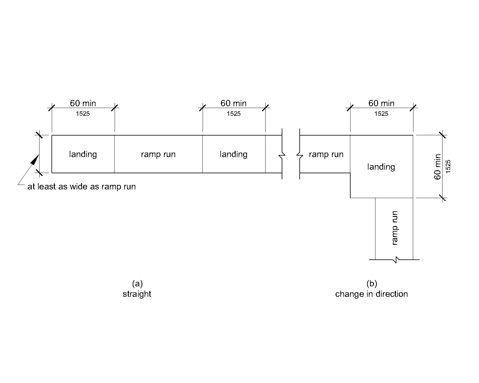
V405.7 Landings
Ramps shall have landings at the top and the bottom of each ramp run. Landings shall comply with V405.7.
Advisory V405.7 Landings. Ramps that do not have level landings at changes in direction can create a compound slope that will not meet the requirements of this document. Circular or curved ramps continually change direction. Curvilinear ramps with small radii also can create compound cross slopes and cannot, by their nature, meet the requirements for accessible routes. A level landing is needed at the accessible door to permit maneuvering and simultaneously door operation.
V405.7.1 Slope
Landings shall comply with V302. Changes in level are not permitted.
EXCEPTION
Slopes not steeper than 1:48 shall be permitted.
V405.7.2 Width
The landing clear width shall be at least as wide as the widest ramp run leading to the landing.
V405.7.3 Length
The landing clear length shall be 60 inches (1525 mm) long minimum.
EXCEPTION
Where the largest deck is less than 3,000 square feet (279 m²), the landing clear length shall be permitted to be 48 inches (1220 mm) long minimum.
V405.7.4 Change in Direction
Ramps that change direction between runs at landings shall have a clear landing 60 inches (1525 mm) minimum by 60 inches (1525 mm) minimum.
V405.7.5 Doorways
Where doorways are located adjacent to a ramp landing, maneuvering clearances required by V404.2.4 and V404.3.2 shall be permitted to overlap the required landing area.
V405.8 Handrails
Ramp runs with a rise greater than 6 inches (150 mm) shall have handrails complying with V503.
V405.9 Edge Protection
Edge protection complying with V405.9.1 or V405.9.2 shall be provided on each side of ramp runs and at each side of ramp landings.
EXCEPTIONS
- Edge protection shall not be required on ramps that are not required to have handrails and have sides complying with V406.3.
- Edge protection shall not be required on the sides of ramp landings serving an adjoining ramp run, gangway run, or stairway.
- Edge protection shall not be required on the sides of ramp landings having a vertical drop-off of ½ inch (13 mm) maximum within 10 inches (255 mm) horizontally of the minimum landing area specified in V405.7.
V405.9.1 Extended Deck Surface
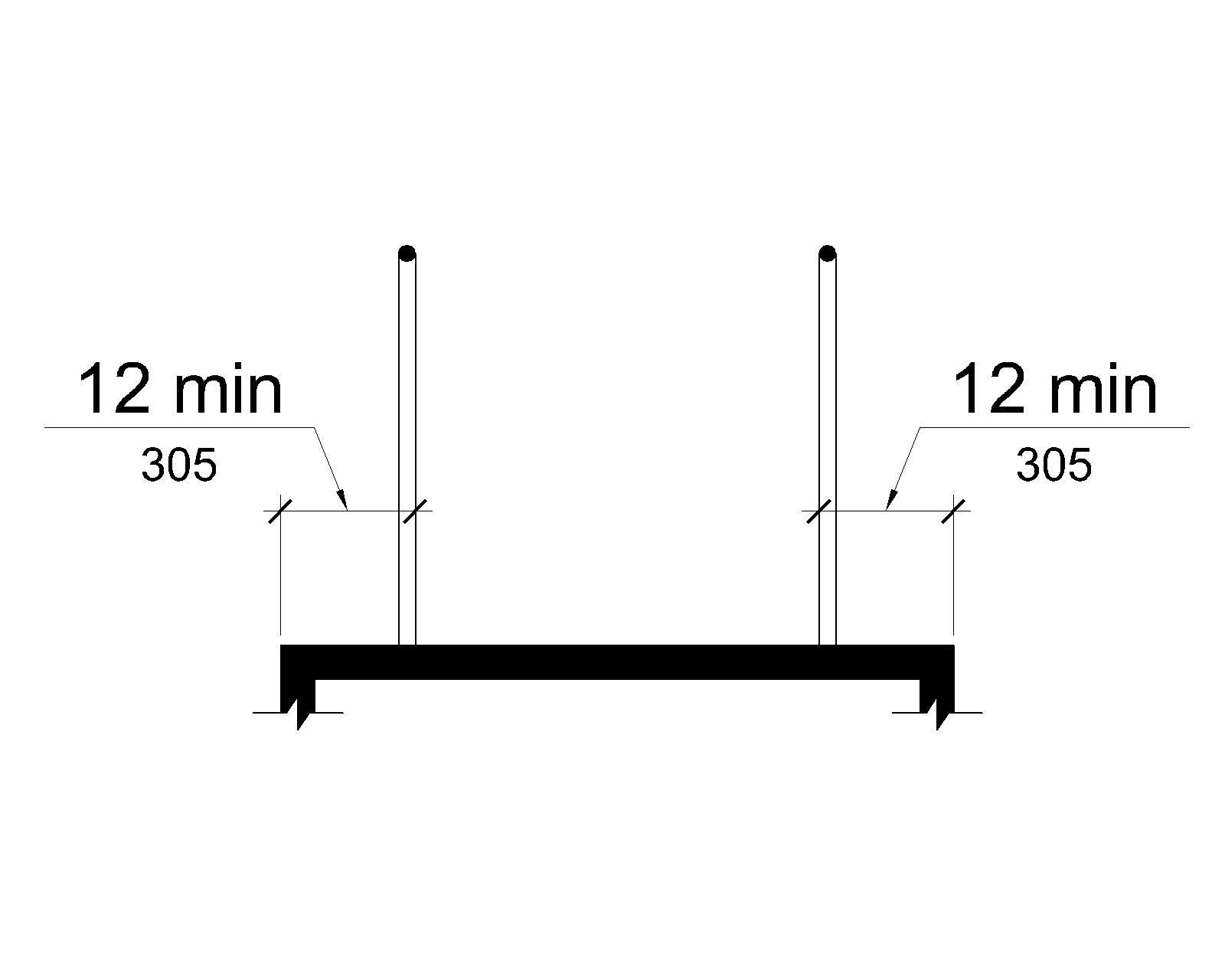
The deck surface of the ramp run or landing shall extend 12 inches (305 mm) minimum beyond the inside face of a handrail complying with V503.
Advisory V405.9.1 Extended Deck Surface. The extended surface prevents wheelchair casters and crutch tips from slipping off the ramp surface.
V405.9.2 Curb or Barrier
A curb or barrier shall be provided that prevents the passage of a 4 inch (100 mm) diameter sphere, where any portion of the sphere is within 4 inches (100 mm) of the finish deck surface.
V405.10 Wet Conditions
Landings subject to wet conditions shall be designed to prevent the accumulation of water.
V406 Curb Ramps
V406.1 General
Curb ramps shall comply with V406, V405.2 through V405.5, and V405.10.
V406.2 Counter Slope
Counter slopes of adjoining gutters and vehicular way surfaces immediately adjacent to the curb ramp shall not be steeper than 1:20. The adjacent surfaces at transitions at curb ramps to walks, gutters, and vehicular ways shall be at the same level.
V406.3 Sides of Curb Ramps
Where provided, curb ramp flares shall not be steeper than 1:10.
V406.4 Landings
Landings shall be provided at the tops of curb ramps. The landing clear length shall be 36 inches (915 mm) minimum. The landing clear width shall be at least as wide as the curb ramp, excluding flared sides, leading to the landing.
EXCEPTION
In alterations, where there is no landing at the top of existing curb ramps, curb ramp flares shall be provided and shall not be steeper than 1:12.
V407 Elevators
V407.1 General
Elevators shall comply with V407. They shall be passenger elevators. Elevator operation shall be automatic.
Advisory V407.1 General. The U.S. Department of Justice ADA regulations (28 CFR 35.133, Maintenance of accessible features, and 28 CFR 36.211, Maintenance of accessible features) require that accessible features be maintained in working order so that they are accessible to and usable by those people they are intended to benefit. Isolated or temporary interruptions in service due to maintenance or repairs may be unavoidable; however, failure to take prompt action to effect repairs could constitute a violation of the regulations.
Although section V407.1 does not reference a safety standard for elevators, it is recommended that ASME A17.1 (Safety Code for Elevators and Escalators) be used by US Flag passenger vessels.
V407.2 Elevator Landing Requirements
Elevator landings shall comply with V407.2.
V407.2.1 Call Controls
Where elevator call buttons or keypads are provided, they shall comply with V407.2.1 and V309.4. Call buttons shall be raised or flush.
EXCEPTION
In alterations, existing elevators shall be permitted to have recessed call buttons.
V407.2.1.1 Height
Call buttons and keypads shall be located within one of the reach ranges specified in V308, measured to the centerline of the highest operable part.
EXCEPTION
In alterations, existing call buttons and existing keypads shall be permitted to be located at 54 inches (1370 mm) maximum above the finish deck surface measured to the centerline of the highest operable part.
V407.2.1.2 Size
Call buttons shall be ¾ inch (19 mm) minimum in the smallest dimension.
EXCEPTION
In alterations, existing elevator call buttons shall not be required to comply with V407.2.1.2.
V407.2.1.3 Clear Deck Space
A clear deck space complying with V305 shall be provided at call controls.
Advisory V407.2.1.3 Clear Deck Space. The deck space required at elevator call buttons must remain free of obstructions including ashtrays, plants, and other decorative elements that prevent wheelchair users and others from reaching the call buttons. The height of the clear deck space is considered to be a volume from the deck surface to 80 inches (2030 mm) above the deck surface. Recessed ashtrays should not be placed near elevator call buttons so that persons who are blind or visually impaired do not inadvertently contact them or their contents as they reach for the call buttons.
V407.2.1.4 Location
The call button that designates the up direction shall be located above the call button that designates the down direction.
EXCEPTION
Destination-oriented elevators shall not be required to comply with V407.2.1.4.
Advisory V407.2.1.4 Location Exception. A destination-oriented elevator system provides lobby controls enabling passengers to select deck stops, lobby indicators designating which elevator to use, and a car indicator designating the deck at which the car will stop. Responding cars are programmed for maximum efficiency by reducing the number of stops any passenger experiences.
V407.2.1.5 Signals
Call buttons shall have visible signals to indicate when each call is registered and when each call is answered.
EXCEPTIONS
- Destination-oriented elevators shall not be required to comply with V407.2.1.5 if visible and audible signals complying with V407.2.2 indicating which elevator car to enter are provided.
- In alterations, existing elevators shall not be required to comply with V407.2.1.5.
V407.2.1.6 Keypads
Where keypads are provided, keypads shall be in a standard telephone keypad arrangement and shall comply with V407.4.7.2.
V407.2.2 Hall Signals
Hall signals, including in-car signals, shall comply with V407.2.2.
V407.2.2.1 Visible and Audible Signals
A visible and audible signal shall be provided at each hoistway entrance to indicate which car is answering a call and the car’s direction of travel. Where in-car signals are provided, they shall be visible from the deck area adjacent to the hall call buttons.
EXCEPTIONS
- Visible and audible signals shall not be required at each destination-oriented elevator where a visible and audible signal complying with V407.2.2 is provided indicating the elevator car designation information.
- In alterations to existing elevators, a signal indicating the direction of car travel shall not be required.
V407.2.2.2 Visible Signals
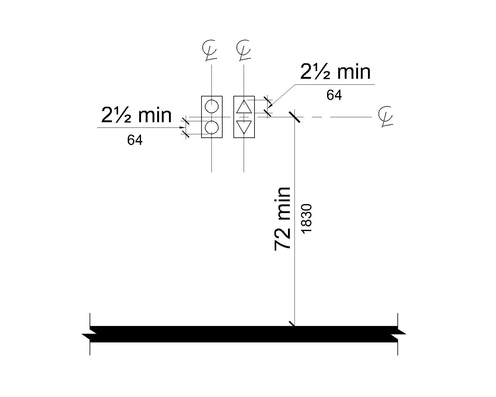
Visible signal fixtures shall be centered at 72 inches (1830 mm) minimum above the finish deck surface. The visible signal elements shall be 2½ inches (64 mm) minimum measured along the vertical centerline of the element. Signals shall be visible from the deck area adjacent to the hall call button.
EXCEPTIONS
- Destination-oriented elevators shall be permitted to have signals visible from the deck area adjacent to the hoistway entrance.
- In alterations, existing elevators shall not be required to comply with V407.2.2.2.
V407.2.2.3 Audible Signals
Audible signals shall sound once for the up direction and twice for the down direction, or shall have verbal annunciators that indicate the direction of elevator car travel. Audible signals shall have a frequency of 1500 Hz maximum. Verbal annunciators shall have a frequency of 300 Hz minimum and 3000 Hz maximum. The audible signal and verbal annunciator shall be 10 dB minimum above ambient, but shall not exceed 80 dB maximum, measured at the hall call button.
EXCEPTIONS
- Destination-oriented elevators shall not be required to comply with V407.2.2.3 if the audible tone and verbal announcement is the same as those given at the call button or call button keypad.
- In alterations, existing elevators shall not be required to comply with the requirements for frequency and dB range of audible signals.
V407.2.2.4 Differentiation
Each destination-oriented elevator in a bank of elevators shall have audible and visible means for differentiation.
V407.2.3 Hoistway Signs
Signs at elevator hoistways shall comply with V407.2.3.
V407.2.3.1 Deck Designation
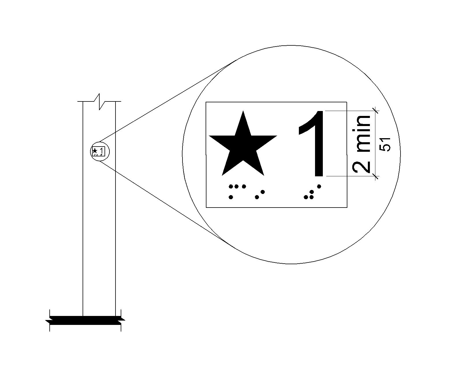
Deck designations complying with V703.2 and V703.4.1 shall be provided on both jambs of elevator hoistway entrances. Deck designations shall be provided in both tactile characters and braille. Tactile characters shall be 2 inches (51 mm) high minimum. Where vessel entry points are provided on only one deck, a tactile star shall be provided on both jambs at the entry deck.
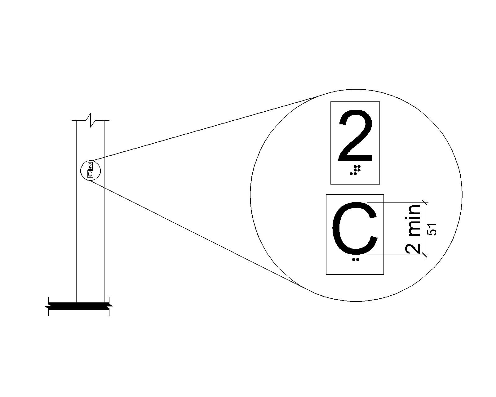
V407.2.3.2 Car Designations
Destination-oriented elevators shall provide tactile car identification complying with V703.2 on both jambs of the hoistway immediately below the deck designation. Car designations shall be provided in both tactile characters and braille. Tactile characters shall be 2 inches (51 mm) high minimum.
V407.3 Elevator Door Requirements
Hoistway and car doors shall comply with V407.3.
V407.3.1 Type
Elevator doors shall be the horizontal sliding type. Car gates shall be prohibited.
V407.3.2 Operation
Elevator hoistway and car doors shall open and close automatically.
EXCEPTION
In alterations, existing manually operated hoistway swing doors shall be permitted if they comply with V404.2.3 and V404.2.9. Car door closing shall not be initiated until the hoistway door is closed.
V407.3.3 Reopening Device
Elevator doors shall be provided with a reopening device complying with V407.3.3 that shall stop and reopen a car door and hoistway door automatically if the door becomes obstructed by an object or person.
EXCEPTION
In alterations, existing elevators with manually operated doors shall not be required to comply with V407.3.3.
V407.3.3.1 Height
The device shall be activated by sensing an obstruction passing through the opening at 5 inches (125 mm) nominal and 29 inches (735 mm) nominal above the finish deck surface.
V407.3.3.2 Contact
The device shall not require physical contact to be activated, although contact is permitted to occur before the door reverses.
V407.3.3.3 Duration
Door reopening devices shall remain effective for 20 seconds minimum.
V407.3.4 Door and Signal Timing
The minimum acceptable time from notification that a car is answering a call or notification of the car assigned at the means for the entry of destination information until the doors of that car start to close shall be calculated from the following equation: T = D/(1.5 ft/s) or T = D/(455 mm/s) = 5 seconds minimum where T equals the total time in seconds and D equals the distance (in feet or millimeters) from the point in the lobby or corridor 60 inches (1525 mm) directly in front of the farthest call button controlling that car to the centerline of its hoistway door.
EXCEPTIONS
- For cars with in-car lanterns, T shall be permitted to begin when the signal is visible from the point 60 inches (1525 mm) directly in front of the farthest hall call button and the audible signal is sounded.
- Destination-oriented elevators shall not be required to comply with V407.3.4.
V407.3.5 Door Delay
Elevator doors shall remain fully open in response to a car call for 3 seconds minimum.
V407.3.6 Width
The width of elevator doors shall comply with Table V407.4.1.
EXCEPTION
In alterations to existing elevators, a power-operated car door complying with V404.2.3 shall be permitted.
V407.4 Elevator Car Requirements
Elevator cars shall comply with V407.4.
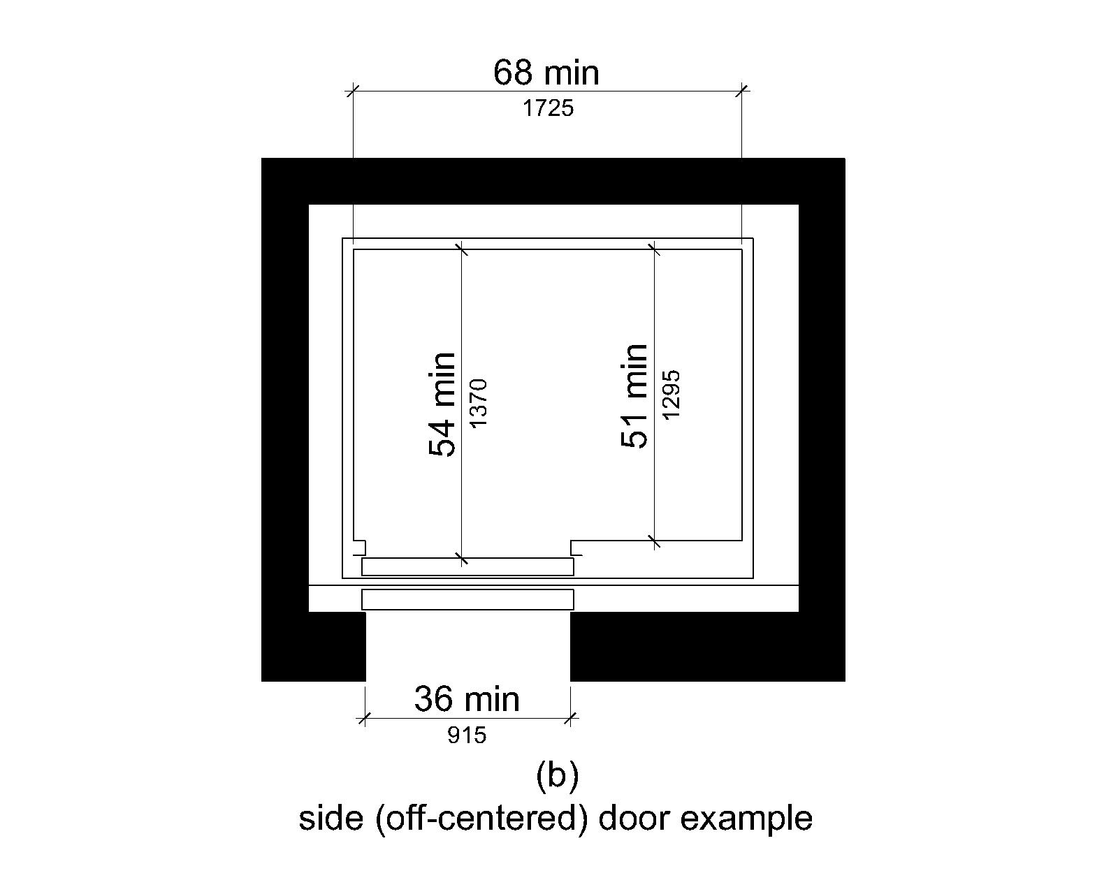
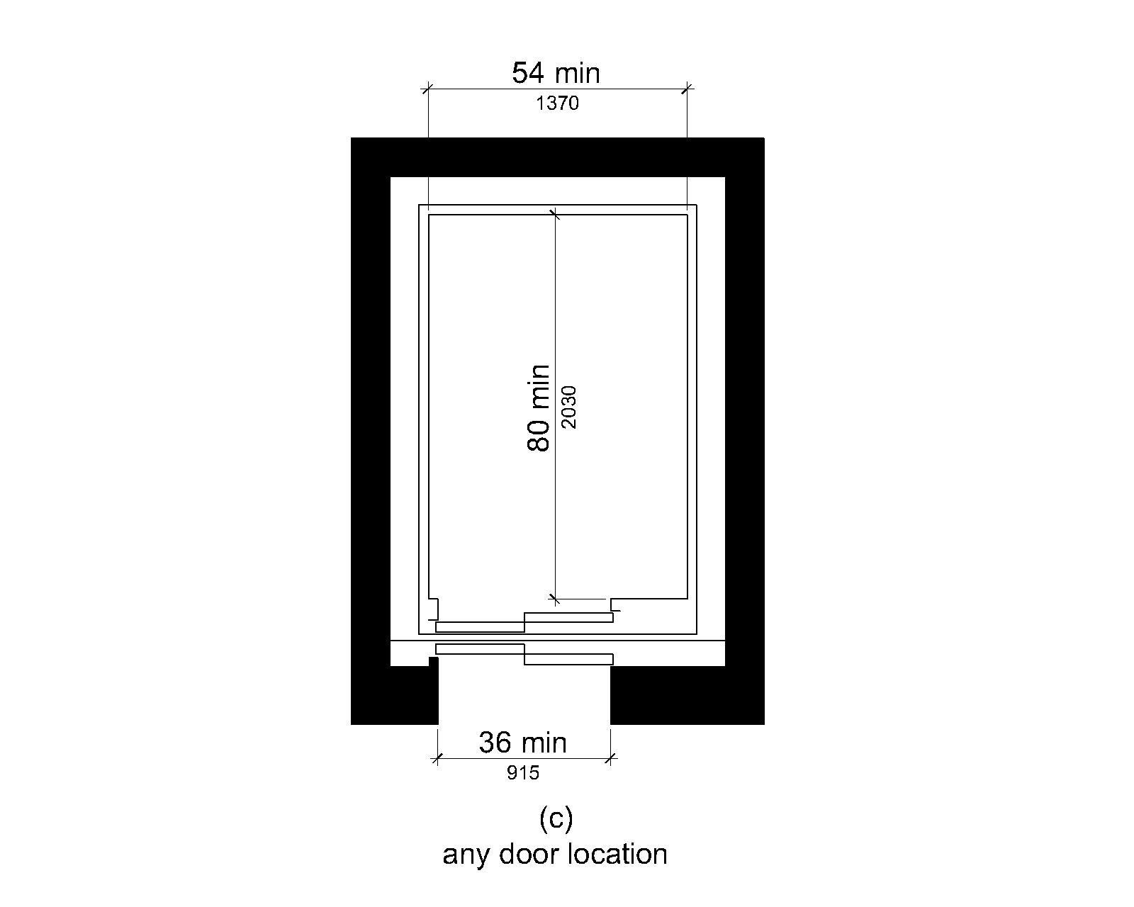
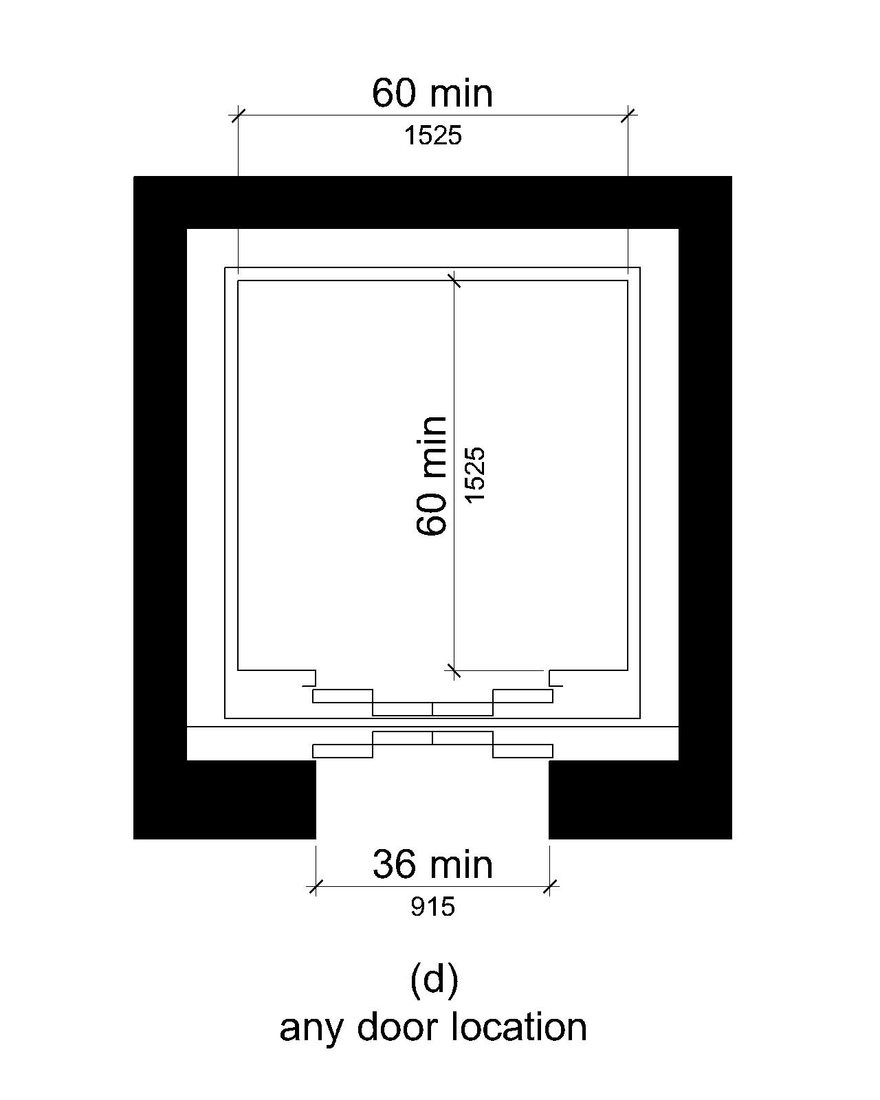
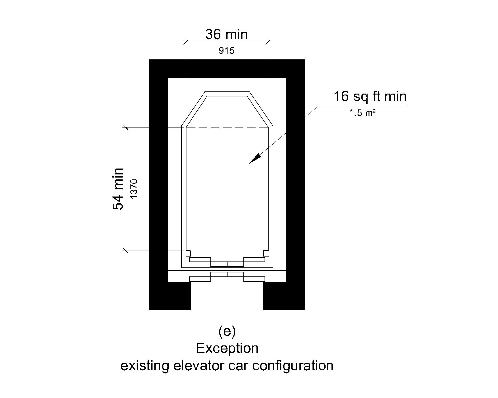
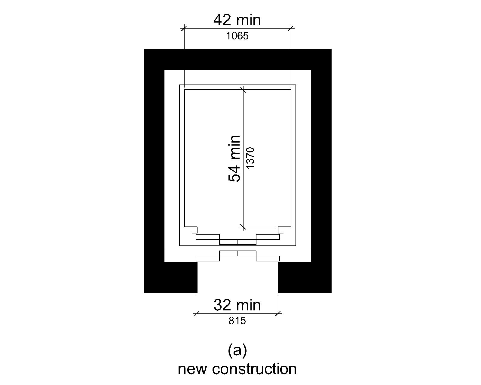
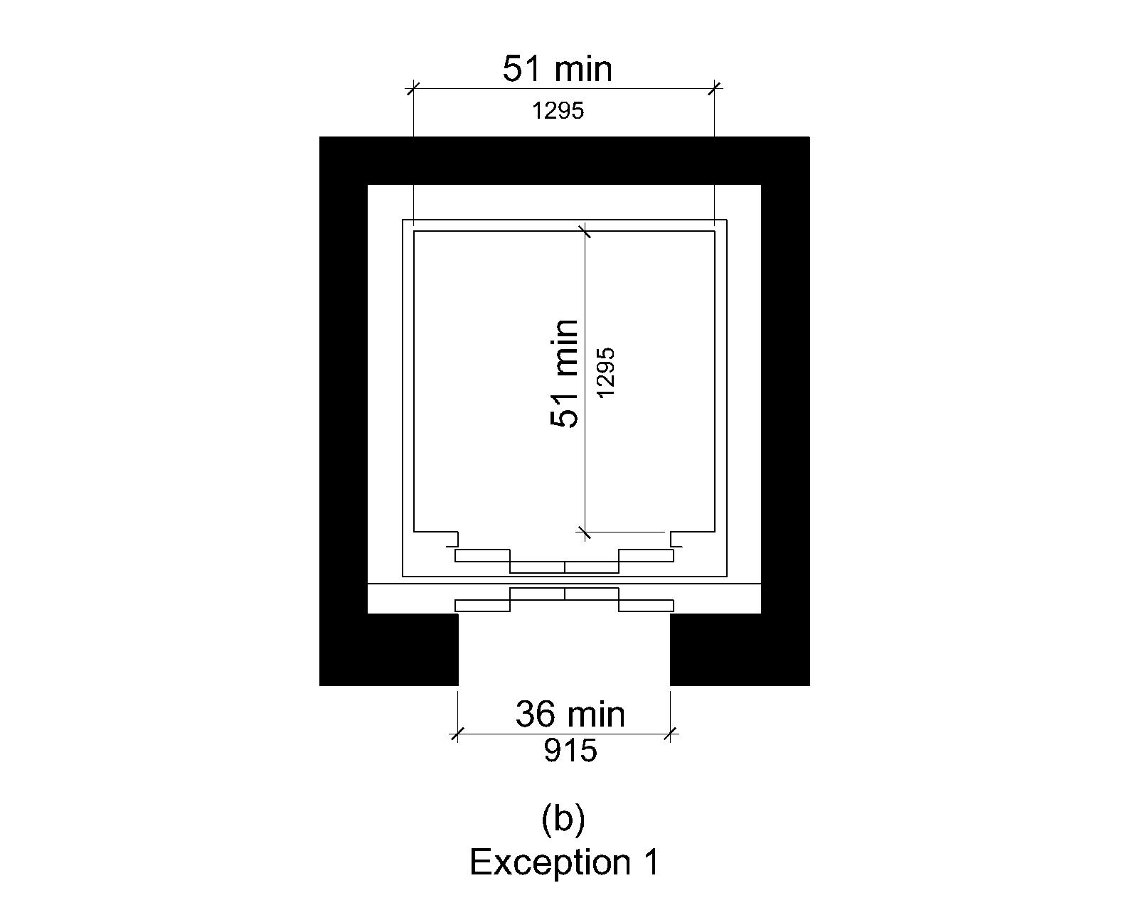
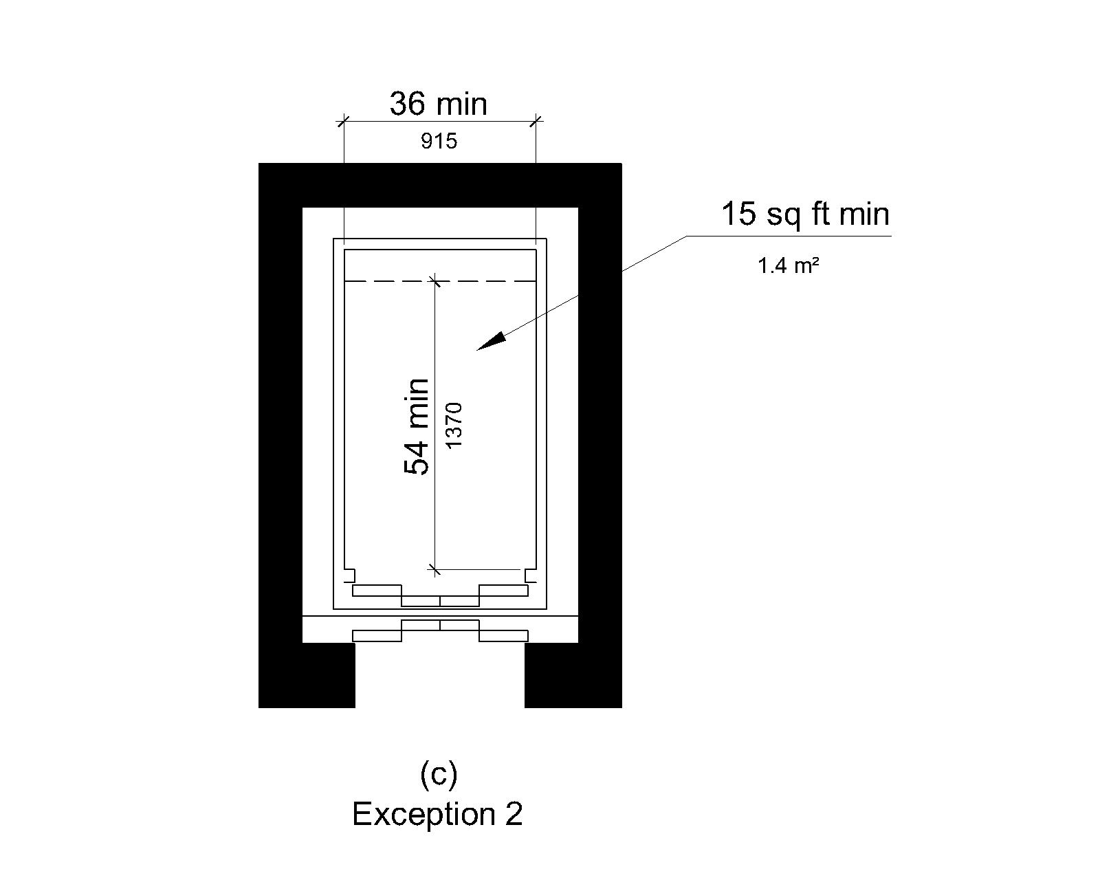
V407.4.1 Car Dimensions
Inside dimensions of elevator cars and clear width of elevator doors shall comply with Table V407.4.1.
EXCEPTION. In alterations, existing elevator car configurations that provide a clear deck area 16 square feet (1.5 m²) minimum, and an inside clear depth 54 inches (1370 mm) minimum and an inside clear width 36 inches (915 mm) minimum shall be permitted.
| Minimum Dimensions | ||||
|---|---|---|---|---|
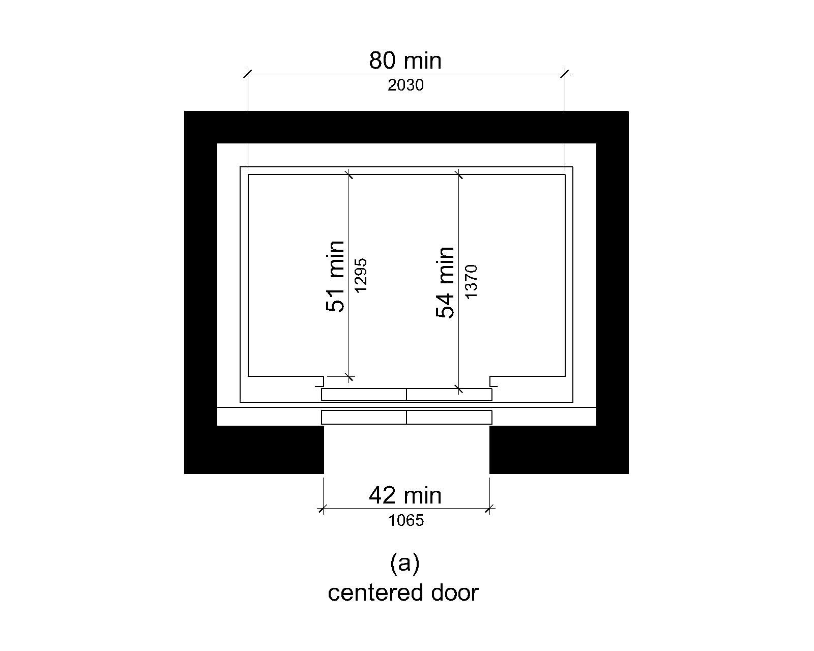
| Door Location | Door Clear Width | Inside Car, Side to Side | Inside Car, Back Wall to Front Return | Inside Car, Back Wall to Inside Face of Door |
| Centered | 42 inches (1065 mm) |
80 inches (2030 mm) |
51 inches (1295 mm) |
54 inches (1370 mm) |
| Any | 36 inches (915 mm)1 |
68 inches (1725 mm) |
51 inches (1295 mm) |
54 inches (1370 mm) |
| Any | 36 inches (915 mm)1 |
54 inches (1370 mm) |
80 inches (2030 mm) |
80 inches (2030 mm) |
| Any | 36 inches (915 mm)1 |
60 inches (1525 mm)2 |
60 inches (1525 mm)2 |
60 inches (1525 mm)2 |
Table Legend:
- A tolerance of minus 5/8 inch (16 mm) is permitted.
- Other car configurations that provide a turning space complying with V304 with the door closed shall be permitted.
V407.4.2 Deck Surfaces
Deck surfaces in elevator cars shall comply with V302 and V303.
V407.4.3 Platform to Hoistway Clearance
The clearance between the car platform sill and the edge of any hoistway landing shall be 1¼ inch (32 mm) maximum.
V407.4.4 Leveling
Each car shall be equipped with a self-leveling feature that will automatically bring and maintain the car at deck landings within a tolerance of ½ inch (13 mm) under rated loading to zero loading conditions.
V407.4.5 Illumination
The level of illumination at the car controls, platform, car threshold, and car landing sill shall be 5 foot candles (54 lux) minimum.
V407.4.6 Elevator Car Controls
Where provided, elevator car controls shall comply with V407.4.6 and V309.4.
EXCEPTION
In alterations to existing elevators, where a new car operating panel complying with V407.4.6 is provided, existing car operating panels shall not be required to comply with V407.4.6.
V407.4.6.1 Location
Controls shall be located within one of the reach ranges specified in V308.
EXCEPTIONS
- Where the elevator panel serves more than 16 openings and a parallel approach is provided, buttons with deck designations shall be permitted to be 54 inches (1370 mm) maximum above the finish deck surface.
- In alterations to existing elevators, car control buttons with deck designations shall be permitted to be located 54 inches (1370 mm) maximum above the finish deck surface where a parallel approach is provided.
V407.4.6.2 Buttons
Car control buttons with deck designations shall comply with V407.4.6.2 and shall be raised or flush.
EXCEPTION
In alterations to existing elevators, buttons shall be permitted to be recessed.
V407.4.6.2.1 Size
Buttons shall be ¾ inch (19 mm) minimum in their smallest dimension.
V407.4.6.2.2 Arrangement
Buttons shall be arranged with numbers in ascending order. When two or more columns of buttons are provided, they shall read from left to right.
V407.4.6.3 Keypads
Car control keypads shall be in a standard telephone keypad arrangement and shall comply with V407.4.7.2.
V407.4.6.4 Emergency Controls
Emergency controls shall comply with V407.4.6.4.
V407.4.6.4.1 Height
Emergency control buttons shall have their centerlines 35 inches (890 mm) minimum above the finish deck surface.
V407.4.6.4.2 Location
Emergency controls, including the emergency alarm, shall be grouped at the bottom of the panel.
V407.4.7 Designations and Indicators of Car Controls
Designations and indicators of car controls shall comply with V407.4.7.
EXCEPTION
In alterations to existing elevators, where a new car operating panel complying with V407.4.7 is provided, existing car operating panels shall not be required to comply with V407.4.7.
V407.4.7.1 Buttons
Car control buttons shall comply with V407.4.7.1.
V407.4.7.1.1 Type
Control buttons shall be identified by tactile characters complying with V703.2.
V407.4.7.1.2 Location
Raised character and braille designations shall be placed immediately to the left of the control button to which the designations apply.
EXCEPTION
In alterations, where space on an existing car operating panel precludes tactile markings to the left of the controls, markings shall be placed as near to the controls as possible.
V407.4.7.1.3 Symbols
The control button for the emergency stop, alarm, door open, door close, entry deck, and phone, shall be identified with tactile symbols shown in Figure V407.4.7.1.3.
EXCEPTION.Where a passenger vessel has more than one entry deck, the entry deck tactile symbol is not required.
| Control Button | Tactile Symbol | Braille Message |
|---|---|---|
| Emergency Stop | “ST”OP Three cells |
|
| Alarm | AL“AR”M Four cells |
|
| Door Open | OP“EN” Three cells |
|
| Door Close | CLOSE Five cells |
|
| Entry Deck | MA“IN” Three cells |
|
| Phone | PH“ONE” Four cells |
V407.4.7.1.4 Visible Indicators
Buttons with deck designations shall be provided with visible indicators to show that a call has been registered. The visible indication shall extinguish when the car arrives at the designated deck.
V407.4.7.2 Keypads
Keypads shall be identified by characters complying with V703.5 and shall be centered on the corresponding keypad button. The number five key shall have a single raised dot. The dot shall be 0.118 inch (3 mm) to 0.120 inch (3.05 mm) base diameter and in other aspects comply with Table V703.3.1.
V407.4.8 Car Position Indicators
Audible and visible car position indicators shall be provided in elevator cars.
V407.4.8.1 Visible Indicators
Visible indicators shall comply with V407.4.8.1.
V407.4.8.1.1 Size
Characters shall be ½ inch (13 mm) high minimum.
V407.4.8.1.2 Location
Indicators shall be located above the car control panel or above the door.
V407.4.8.1.3 Deck Arrival
As the car passes a deck and when a car stops at a deck served by the elevator, the corresponding character shall illuminate.
EXCEPTION
Destination-oriented elevators shall not be required to comply with V407.4.8.1.3 if the visible indicators extinguish when the call has been answered.
V407.4.8.1.4 Destination Indicator
In destination-oriented elevators, a display shall be provided in the car with visible indicators to show car destinations.
V407.4.8.2 Audible Indicators
Audible indicators shall comply with V407.4.8.2.
V407.4.8.2.1 Signal Type
The signal shall be an automatic verbal annunciator which announces the deck at which the car is about to stop.
EXCEPTION
For elevators other than destination-oriented elevators that have a rated speed of 200 feet per minute (1 m/s) or less, a non-verbal audible signal with a frequency of 1500 Hz maximum which sounds as the car passes or is about to stop at a deck served by the elevator shall be permitted.
V407.4.8.2.2 Signal Level
The verbal annunciator shall be 10 dB minimum above ambient, but shall not exceed 80 dB, measured at the annunciator.
V407.4.8.2.3 Frequency
The verbal annunciator shall have a frequency of 300 Hz minimum to 3000 Hz maximum.
V407.4.9 Emergency Communication
Where provided, emergency two-way communication systems shall comply with V308 and shall provide a visual signal in the elevator car acknowledging that an emergency signal was received at the bridge of the vessel or other space where emergency actions are directed. Tactile symbols and characters shall be provided adjacent to the operable parts of the system in the elevator car and shall comply with V703.2.
V408 Limited Use-Limited Application Elevators
V408.1 General
Limited use-limited application elevators shall comply with V408. They shall be passenger elevators. Elevator operation shall be automatic.
Advisory V408.1 General. Although section V408.1 does not reference a safety standard for elevators, it is recommended that ASME A17.1, Safety Code for Elevators and Escalators, be used by US flag passenger vessels.
V408.2 Elevator Landings
Landings serving limited-use/limited-application elevators shall comply with V408.2.
V408.2.1 Call Buttons
Elevator call buttons and keypads shall comply with V407.2.1.
V408.2.2 Hall Signals
Hall signals shall comply with V407.2.2.
V408.2.3 Hoistway Signs
Signs at elevator hoistways shall comply with V407.2.3.1.
V408.3 Elevator Doors
Elevator hoistway doors shall comply with V408.3.
V408.3.1 Sliding Doors
Sliding hoistway and car doors shall comply with V407.3.1 through V407.3.3 and V408.4.1.
V408.3.2 Swinging Doors
Swinging hoistway doors shall open and close automatically and shall comply with V404, V407.3.2 and V408.3.2.
V408.3.2.1 Power Operation
Swinging doors shall be power-operated.
Advisory V408.3.2.1 Power Operation. Although section V408.3.2.1 does not reference a safety standard for power-operated swing doors, it is recommended that ANSI/BHMA A156.19, American National Standard for Power Assist and Low Energy Power Operated Doors, be used by US Flag passenger vessels.
V408.3.2.2 Duration
Power-operated swinging doors shall remain open for 20 seconds minimum when activated.
V408.4 Elevator Cars
Elevator cars shall comply with V408.4.
V408.4.1 Car Dimensions and Doors
Elevator cars shall provide a clear width 42 inches (1065 mm) minimum and a clear depth 54 inches (1370 mm) minimum. Car doors shall be positioned at the narrow ends of cars and shall provide 32 inches (815 mm) minimum clear width.
EXCEPTIONS
- Cars that provide a clear width 51 inches (1295 mm) minimum shall be permitted to provide a clear depth 51 inches (1295 mm) minimum provided that car doors provide a clear opening 36 inches (915 mm) wide minimum.
- In alterations, existing elevator cars shall be permitted to provide a clear width 36 inches (915 mm) minimum, clear depth 54 inches (1370 mm) minimum, and a net clear platform area 15 square feet (1.4 m²) minimum.
V408.4.2 Deck Surfaces
Deck surfaces in elevator cars shall comply with V302 and V303.
V408.4.3 Platform to Hoistway Clearance
The platform to hoistway clearance shall comply with V407.4.3.
V408.4.4 Leveling
Elevator car leveling shall comply with V407.4.4.
V408.4.5 Illumination
Elevator car illumination shall comply with V407.4.5.
V408.4.6 Car Controls
Elevator car controls shall comply with V407.4.6. Control panels shall be centered on a side wall and shall comply with V309.
V408.4.7 Designations and Indicators of Car Controls
Designations and indicators of car controls shall comply with V407.4.7.
V408.4.8 Emergency Communications
Car emergency signaling devices complying with V407.4.9 shall be provided.
V409 Platform Lifts
V409.1 General
Platform lifts shall comply with V409. Platform lifts shall not be attendant-operated and shall provide unassisted entry and exit from the lift. The rated load of the platform lifts shall be 450 pounds (204 kg) minimum.
Advisory V409.1 General. Inclined and vertical platform lifts are available for short-distance vertical transportation. Because an accessible route requires an 80 inch (2030 mm) vertical clearance, care should be taken in selecting lifts as they may not be equally suitable for use by people using wheelchairs and people standing. If a lift does not provide 80 inch (2030 mm) vertical clearance, it cannot be considered part of an accessible route in new construction.
The ADA and other Federal civil rights laws require that accessible features be maintained in working order so that they are accessible to and usable by those people they are intended to benefit. Isolated or temporary interruptions in service due to maintenance or repairs may be unavoidable; however, failure to take prompt action to effect repairs could constitute a violation of Federal laws and these requirements.
Although section V409.1 does not reference a safety standard for platform lifts, it is recommended that the provisions in ASME A18.1, Safety Standard for Platform Lifts and Stairway Chairlifts, be used by US Flag passenger vessels where applicable in the marine environment.
V409.2 Platform Surface and Size
The lift platform surface and size shall comply with V302, V303, and V305.
EXCEPTION
Where the largest deck is less than 3,000 square feet (279 m²), the lift platform shall be permitted to be 32 inches (815 mm) wide minimum where the lift platform is approached at the short side.
V409.3 Platform to Runway Clearance
The clearance between the platform sill and the edge of any runway landing shall be 1¼ inch (32 mm) maximum.
V409.4 Operable Parts
Controls for platform lifts shall comply with V309.
V409.5 Doors and Gates
Platform lifts shall have low-energy power-operated doors or gates complying with V404.3. Doors shall remain open for 20 seconds minimum. End doors and gates shall provide a clear width 32 inches (815 mm) minimum. Side doors and gates shall provide a clear width 42 inches (1065 mm) minimum.
EXCEPTION
Platform lifts serving two landings maximum and having doors or gates on opposite sides shall be permitted to have self-closing manual doors or gates.
V410 Gangways
V410.1 General
Gangways that are part of accessible passenger boarding systems shall comply with V410.
V410.2 Slope
Gangway runs shall have a running slope not steeper than 1:12.
EXCEPTIONS
- Where gangways have only one run and the gangways do not exceed a rise of 6 inches (150 mm), the gangways shall be permitted to have running slopes in accordance with Table V410.2.
- Where an existing gangway run or series of gangway runs is replaced or altered, an increase in the length of the gangway run shall not be required to comply with V410.2.
- On vessel carried gangways, where the total length of the gangway run or series of runs is at least as long as the beam of the vessel, gangways shall not be required to comply with V410.2.
- On pier provided gangways, where the total length of a gangway run or series of runs is at least 120 feet (37 m), gangways shall not be required to comply with V410.2.
- On passenger vessels which carry vehicles, where the only way for pedestrian passengers to embark or disembark is by way of a gangway that also functions as a vehicle transfer bridge, gangways shall not be required to comply with V410.2.
| Slope1 | Maximum Rise |
|---|---|
| Steeper than 1:10 but not steeper than 1:8 | 3 inches (75 mm) |
| Steeper than 1:12 but not steeper than 1:10 | 6 inches (150 mm) |
Table Legend:
1.A slope steeper than 1:8 is prohibited.
V410.3 Cross Slope
Cross slope of gangway runs shall not be steeper than 1:48.
Advisory V410.3 Cross Slope. Cross slope is the slope of the surface perpendicular to the direction of travel. It is measured the same way as slope is measured: the rise over the run.
V410.4 Surfaces
Surfaces of gangway runs shall comply with V302. Changes in level other than the running slope and cross slope are not permitted on gangway runs.
EXCEPTIONS
- Where gangways are deployed and conditions result in slopes greater than 1:4, changes in level complying with V303.2 or V303.3 shall be permitted on surfaces of gangway runs.
- Changes in level shall be permitted on gangway run surfaces that extend beyond the minimum clear width specified in V410.5.
V410.5 Clear Width
The clear width of a gangway run and, where handrails are provided, the clear width between handrails shall be 36 inches (915 mm) minimum.
EXCEPTION
Where the largest deck is less than 3,000 square feet (279 m²), the width of gangway runs and the distance between handrails, if provided, shall be permitted to have clear widths of 32 inches (815 mm) minimum.
V410.6 Transition Plates
Transition plates provided at the ends of gangway runs shall contrast visually with adjacent passenger walkways either light-on-dark or dark-on-light.
V410.7 Landings
Gangways shall have landings at the top and the bottom of each gangway run. Landings shall comply with V410.7.
EXCEPTIONS
- Landings shall not be required between transition plates complying with V403 or V405, and gangways.
- On telescoping gangways, landings shall not be required between gangway segments where transition plates are provided which comply with V405.1 through V405.6, and V405.8 through V405.10.
V410.7.1 Slope
Landings shall comply with V302. Changes in level are not permitted.
EXCEPTION
Slopes not steeper than 1:48 shall be permitted.
V410.7.2 Width
The landing clear width shall be at least as wide as the widest gangway run leading to the landing.
V410.7.3 Length
The landing clear length shall be 60 inches (1525 mm) long minimum.
V410.7.4 Change in Direction
Gangways that change direction between runs at landings shall have a clear landing 60 inches (1525 mm) minimum by 60 inches (1525 mm) minimum.
V410.7.5 Doorways
Where doorways are located adjacent to a gangway landing, maneuvering clearances required by V404.2.4 and V404.3.2 shall be permitted to overlap the required landing area.
V410.8 Handrails
Gangway runs with a rise greater than 6 inches (150 mm) shall have handrails complying with V503.
EXCEPTION
Gangways that also function as vehicle transfer bridges shall be permitted to have readily removable handrails.
V410.9 Edge Protection
Edge protection complying with V410.9.1 or V410.9.2 shall be provided on each side of gangway runs and at each side of gangway landings.
EXCEPTIONS
- Edge protection shall not be required on the sides of gangway landings serving an adjoining ramp run, gangway run, or stairway.
- Edge protection shall not be required on the sides of gangway landings having a vertical drop-off of ½ inch (13 mm) maximum within 10 inches (255 mm) horizontally of the minimum landing area specified in V410.7.
V410.9.1 Extended Deck Surface
The deck surface of the gangway run or landing shall extend 12 inches (305 mm) minimum beyond the inside face of a handrail complying with V503.
Advisory V410.9.1 Extended Deck Surface. The extended surface prevents wheelchair casters and crutch tips from slipping off the gangway surface.
V410.9.2 Curb or Barrier
A curb or barrier shall be provided that prevents the passage of a 4 inch (100 mm) diameter sphere, where any portion of the sphere is within 4 inches (100 mm) of the finish deck surface.
V410.10 Wet Conditions
Landings subject to wet conditions shall be designed to prevent the accumulation of water.
V411 Manually Powered Boarding Lifts
V411.1 General
Manually powered boarding lifts shall comply with V411.
V411.2 Design Load
The design load of the lift shall be at least 600 pounds (272 kg). Working parts, such as cables, pulleys, and shafts, which would be expected to wear, and upon which the lift depends for support of the load, shall have a safety factor of at least six, based on the ultimate strength of the material. Nonworking parts, such as platform, frame, and attachment hardware which would not be expected to wear, shall have a safety factor of at least three, based on the ultimate strength of the material.
V411.3 Controls
Where provided, each control for deploying, lowering, raising, and stowing the lift and lowering the roll-off barrier shall require continuous manual pressure by the operators and an inherent design feature or other system shall not allow improper lift sequencing when the lift platform is occupied. The controls shall allow reversal of the lift operation sequence when the lift is occupied.
V411.4 Emergency Operation
The lift, when occupied, shall incorporate an emergency method of lowering.
V411.5 Equipment Failure
The lift, when occupied, shall have provisions to prevent it from falling any faster than 12 inches/second (305 mm/second) and dropping an occupant in the event of a single failure of any load carrying component.
V411.6 Platform Barriers
The lift platform shall be equipped with barriers to prevent any of the wheels of a wheelchair or mobility aid from rolling off the lift during its operation.
V411.7 Platform Surface and Size
The lift platform surface and size shall comply with V302, V303, and V305.
EXCEPTION
Where the lift platform is approached at the long side, the platform shall be permitted to be 56 inches (1420 mm) wide minimum.
V411.8 Platform Approaches
The approaches to the lift platform, or loading-edge barriers used as approaches, shall comply with V403 or V405. Transitions from adjacent deck and pier surfaces shall comply with V303.
EXCEPTIONS
- Ramped approaches to the lift platform shall be permitted to have running slopes not exceeding 1:8 if the rise of the ramps does not exceed 3 inches (75 mm).
- Landings specified in V405.7 shall not be required between ramped approaches and the lift platform.
V411.9 Platform Deflection
The lift platform shall not deflect more than 3 degrees in any direction between its unloaded position and its position when loaded with 600 pounds (272 kg) applied through a 26 inch (660 mm) by 26 inch (660 mm) test pallet at the centroid of the lift platform.
V411.10 Boarding Direction
The lift shall permit both inboard and outboard facing of wheelchairs and mobility aids.
V411.11 Handrails
The platform on the lift shall be equipped with handrails on two sides, which move in tandem with the lift, and which shall be graspable and provide support to standees throughout the entire lift operation. Handrails shall have a usable component 8 inches (205 mm) long minimum, and the top of the gripping surface shall be 30 inches (760 mm) minimum and 38 inches (965 mm) maximum above the platform. The handrails shall be capable of withstanding a force of 100 pounds (449 N) concentrated at any point on the handrail without permanent deformation of the rail or its supporting structure. The handrails shall comply with V503.5 through V503.9.
