
Chapter 3: Technical Requirements
Advisory: Figures are provided for informational purposes only.
R301 General
R301.1 Scope
The technical requirements in Chapter 3 shall apply where required by Chapter 2 or where referenced by a requirement in these guidelines.
R302 Pedestrian Access Routes
R302.1 General
Pedestrian access routes shall comply with R302.
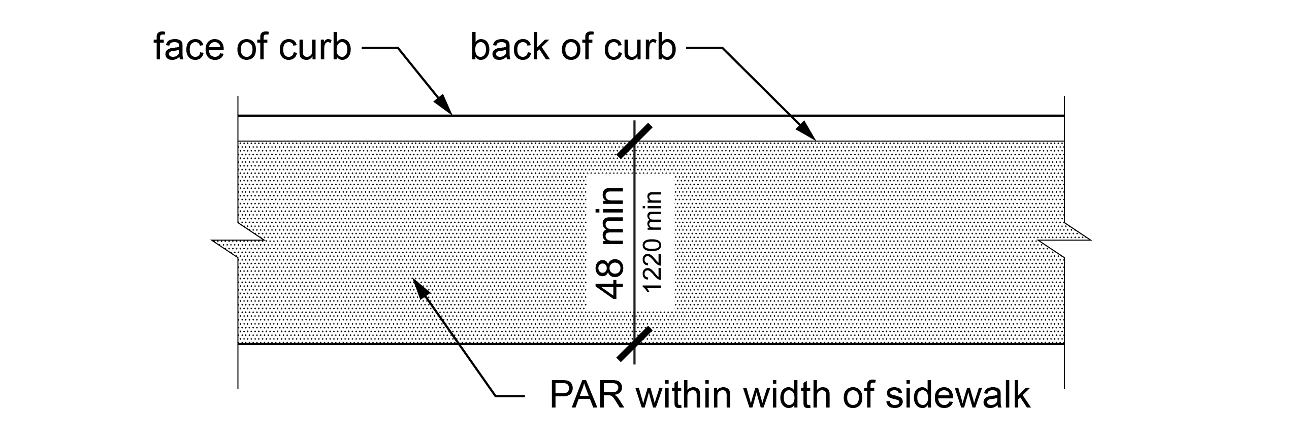
R302.2 Continuous Clear Width
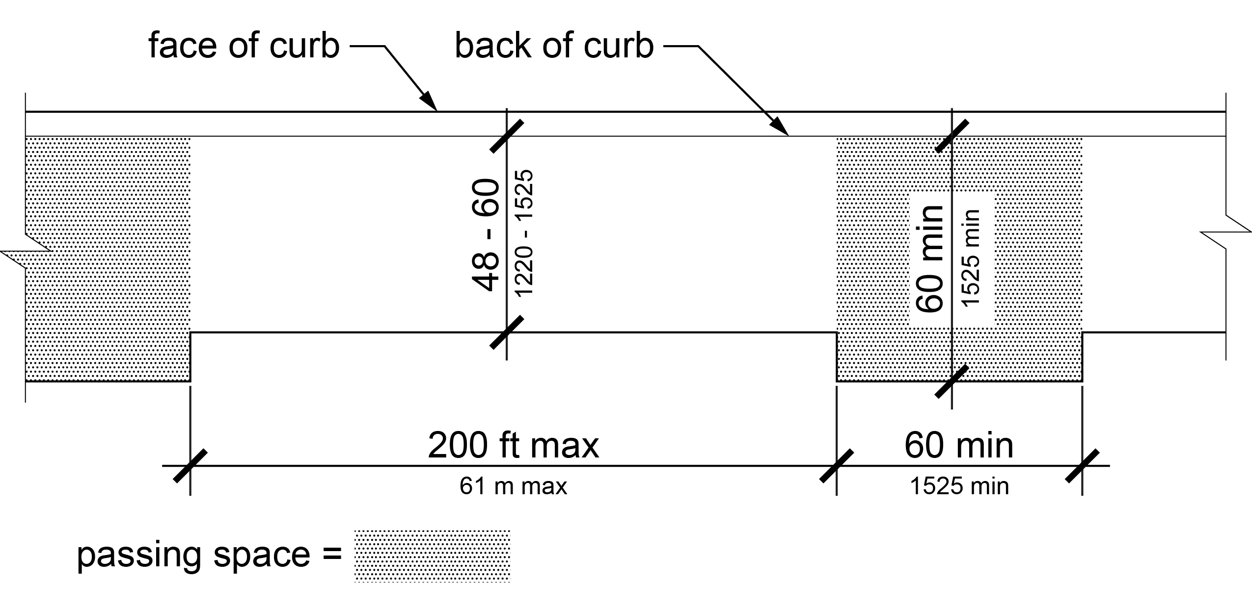
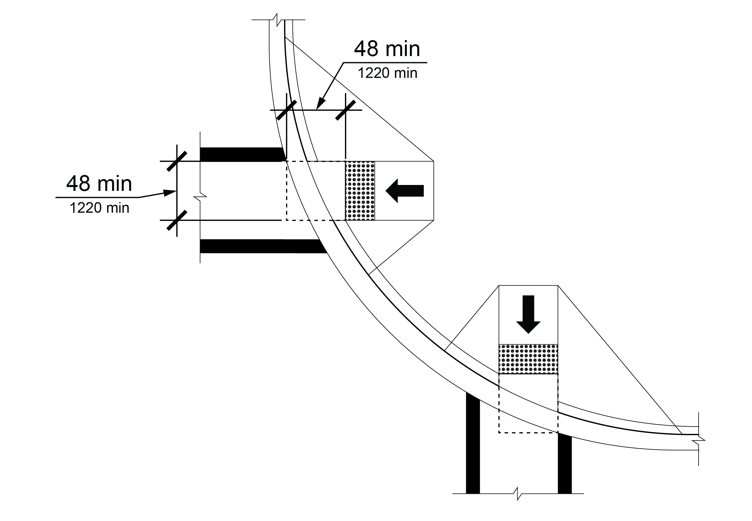
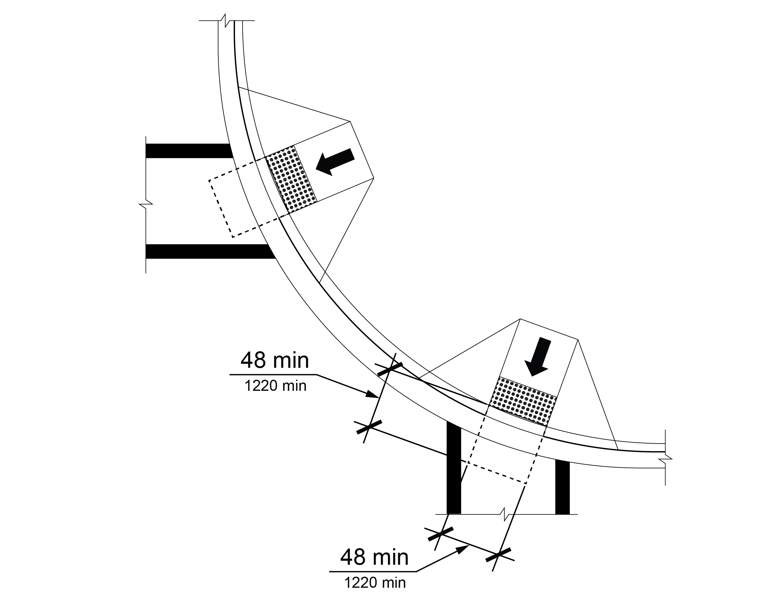
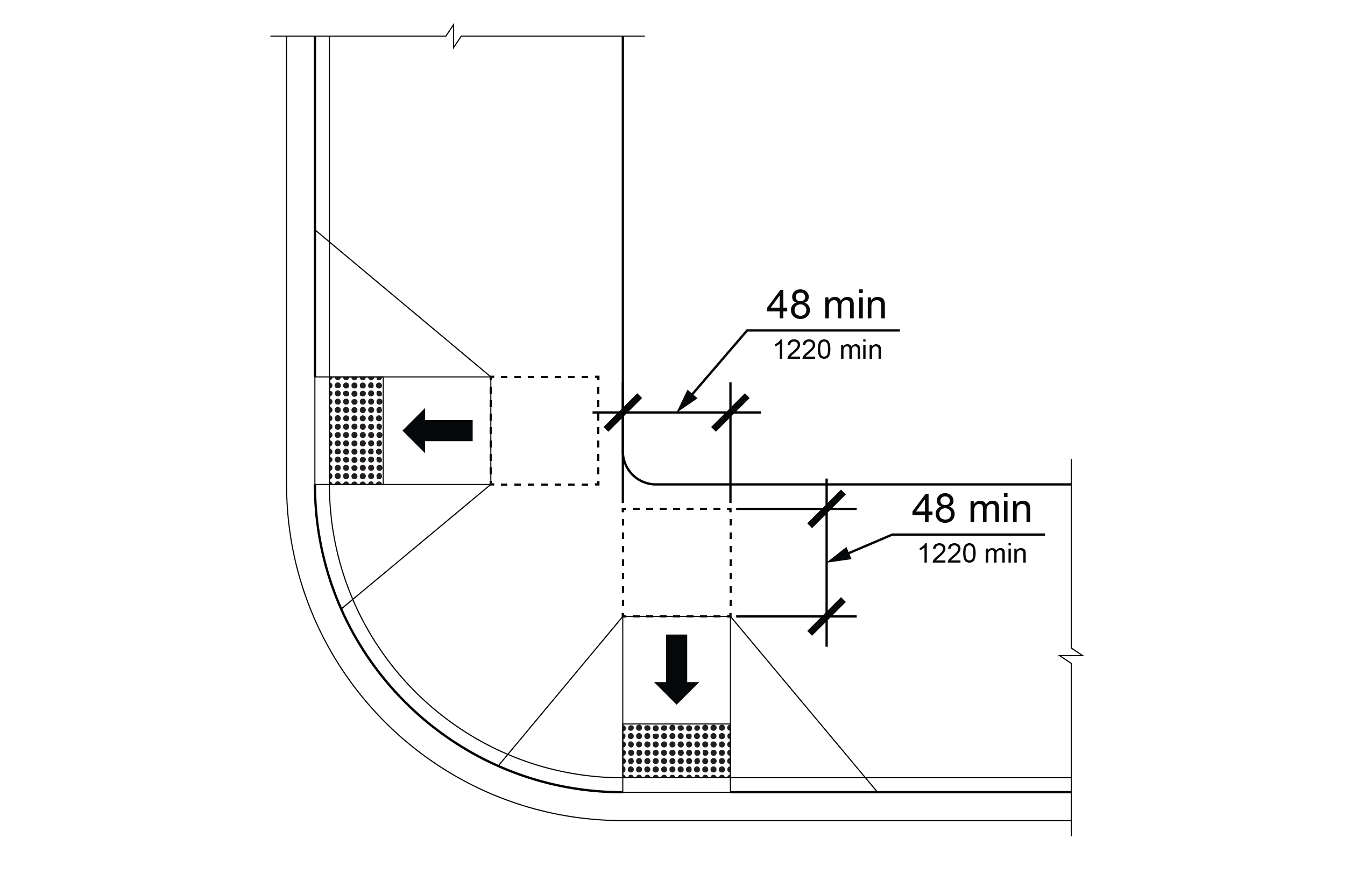
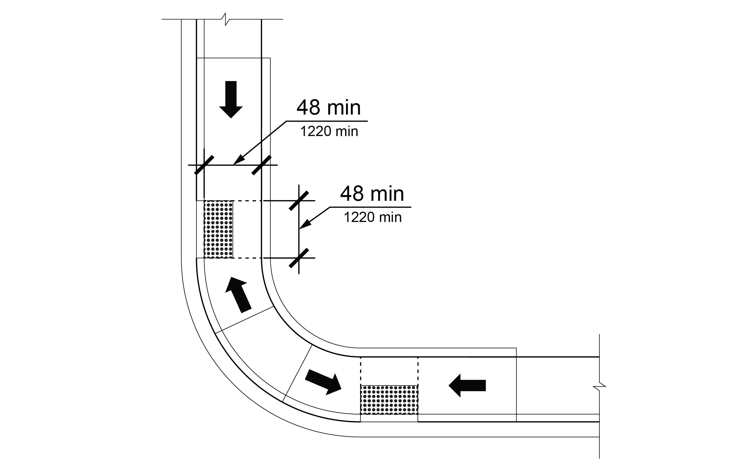
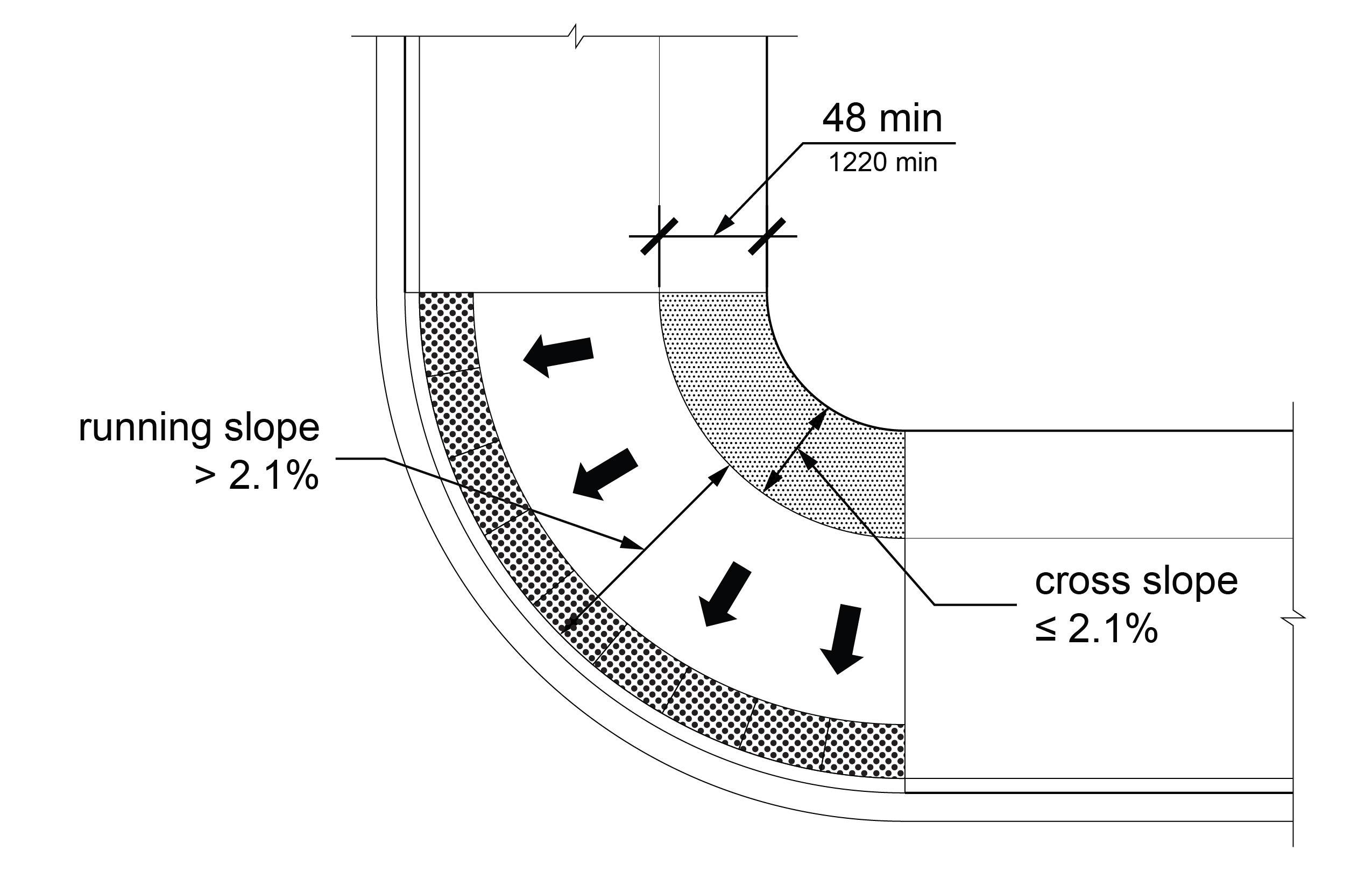
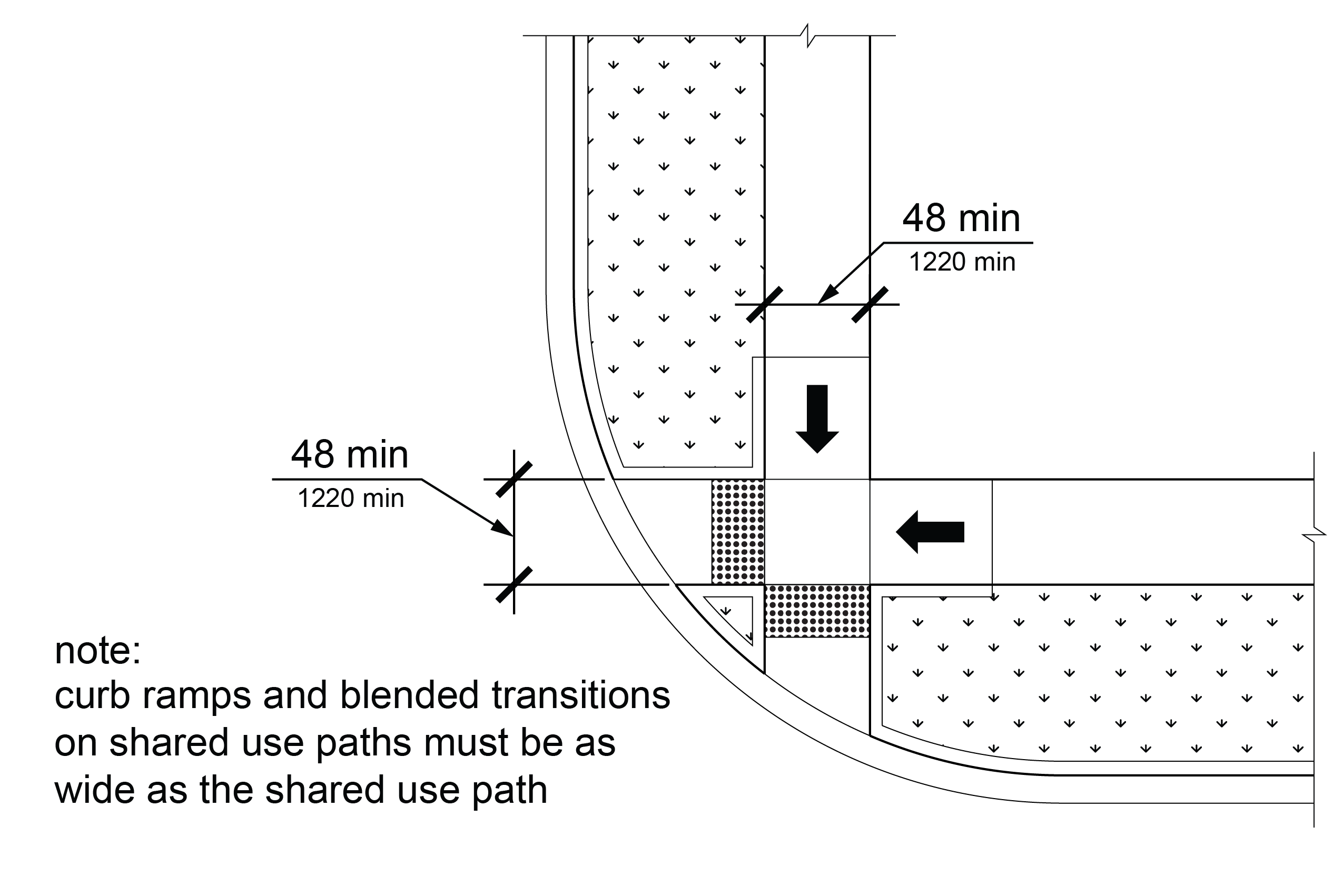
Except as provided in R302.2.1 and R302.2.2, the continuous clear width of pedestrian access routes shall be 48 inches (1220 mm) minimum, exclusive of the width of any curb.
R302.2.1 Medians and Pedestrian Refuge Islands
The clear width of pedestrian access routes crossing medians and pedestrian refuge islands shall be 60 inches (1525 mm) minimum, except that where shared use paths cross medians and pedestrian refuge islands the clear width of the pedestrian access route shall be 60 inches (1525 mm) minimum or at least as wide as the crosswalk, whichever is greater.
R302.2.2 Shared Use Paths
On shared use paths, the clear width of the pedestrian access route shall extend the full width provided for pedestrian circulation on the path. Obstructions, such as bollards, shall not reduce the clear width of the pedestrian access route to less than 48 inches (1220 mm) measured from the edge of the obstruction.
R302.3 Passing Spaces
Where the clear width of pedestrian access routes is less than 60 inches (1525 mm), passing spaces shall be provided at intervals of 200 feet (61 m) maximum. Passing spaces shall be 60 inches (1525 mm) minimum by 60 inches (1525 mm) minimum. Passing spaces and pedestrian access routes are permitted to overlap.
R302.4 Grade
The grade of pedestrian access routes shall comply with R302.4, except the grade of curb ramps and blended transitions shall comply with R304 and the grade of ramps shall comply with R407.
R302.4.1 Within Highway Right-of-Way
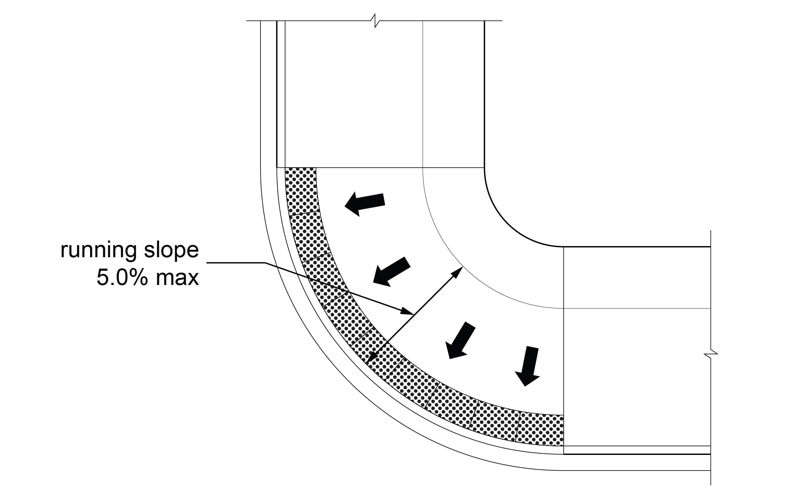
Except as provided in R302.4.3, where a pedestrian access route is contained within a highway right-of-way, the grade of the pedestrian access route shall not exceed 1:20 (5.0%).
EXCEPTION: Where the grade established for the adjacent street exceeds 1:20 (5.0%), the grade of the pedestrian access route shall not exceed the grade established for the adjacent street.
R302.4.2 Not Within Highway Right-of-Way
Where a pedestrian access route is not contained within a highway right-of-way, the grade of the pedestrian access route shall not exceed 1:20 (5.0%).
R302.4.3 Within a Crosswalk
Where a pedestrian access route is contained within a crosswalk, the grade of the pedestrian access route shall be 1:20 (5.0%) maximum.
EXCEPTION: Where roadway design requires superelevation greater than 1:20 (5.0%) at the location of a crosswalk, the grade of the pedestrian access route within the crosswalk may be the same as the superelevation.
R302.5 Cross Slope
The cross slope of a pedestrian access route shall comply with R302.5.
R302.5.1 Not Contained Within a Crosswalk
The cross slope of a pedestrian access route not contained within a crosswalk shall be 1:48 (2.1%) maximum.
EXCEPTION: The portion of a pedestrian access route within a street that connects an accessible parallel on-street parking space to the nearest crosswalk at the end of the block face or the nearest midblock crosswalk is not required to comply with R302.5.
R302.5.2 Contained Within a Crosswalk
The cross slope of a pedestrian access route contained within a crosswalk shall comply with R302.5.2.
R302.5.2.1 Crosswalk with Yield or Stop Control Devices
Where a pedestrian access route is contained within a crosswalk at an intersection approach with yield or stop control devices, the cross slope of the pedestrian access route shall be 1:48 (2.1%) maximum.
R302.5.2.2 Crosswalk at Uncontrolled Approach
Where a pedestrian access route is contained within a crosswalk at an uncontrolled approach, the cross slope of the pedestrian access route shall be 1:20 (5.0%) maximum.
R302.5.2.3 Crosswalk with Traffic Control Signal or Pedestrian Hybrid Beacon
Where a pedestrian access route is contained within a crosswalk at an intersection approach controlled by a traffic control signal or pedestrian hybrid beacon, the cross slope of the pedestrian access route shall be 1:20 (5.0%) maximum.
R302.5.2.4 Midblock and Roundabout Crosswalks
The cross slope of a pedestrian access route within a midblock crosswalk or a crosswalk at a roundabout shall not exceed the street grade.
R302.6 Surfaces
The walking surfaces of pedestrian access routes, elements, and spaces that are required to be accessible shall be stable, firm, and slip resistant and shall comply with R302.6.
R302.6.1 Grade Breaks
Grade breaks shall be flush.
R302.6.2 Changes in Level
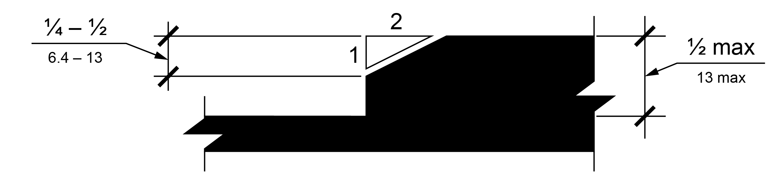
Changes in level of ¼ inch (6.4 mm) maximum shall be permitted to be vertical. Changes in level between ¼ inch (6.4 mm) and ½ inch (13 mm) shall be beveled with a slope not steeper than 1:2 (50.0%). Changes in level greater than ½ inch (13 mm) up to 6 inches shall have a 1:12 (8.3%) maximum slope. Changes in level greater than 6 inches (150 mm) shall comply with R407.

R302.6.3 Horizontal Openings
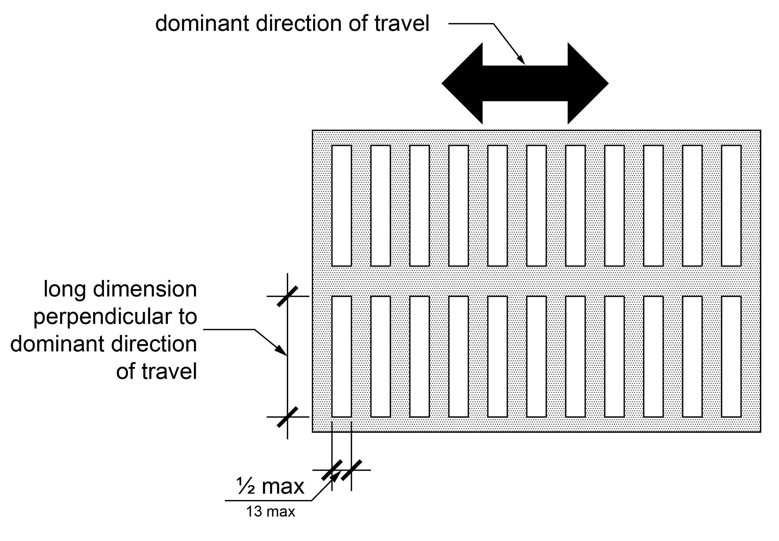
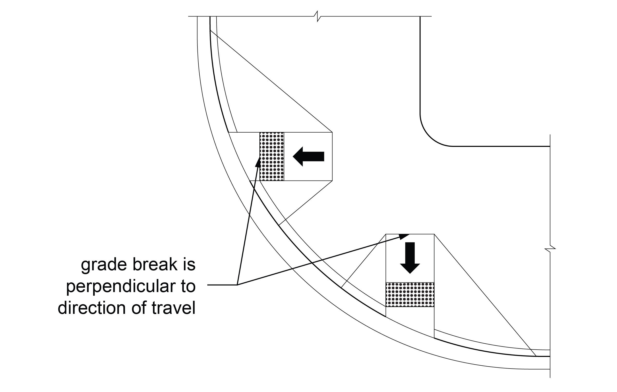
Horizontal openings in ground surfaces, such as those in gratings and joints, other than flangeway gaps (see R302.6.4), shall not allow passage of a sphere larger than ½ inch (13 mm) in diameter. Except where multiple directions of travel intersect, elongated openings are permitted and shall be placed so that the long dimension is perpendicular to the dominant direction of travel.
R302.6.4 Surfaces at Pedestrian At-Grade Rail Crossings
Surfaces at pedestrian at-grade rail crossings shall comply with R302.6.4.
R302.6.4.1 Surface Alignment
Where a pedestrian access route crosses rails at grade, the pedestrian access route surface shall be level and flush with the top of rail at the outer edges of the rails, and the surface between the rails shall be aligned with the top of rail.
R302.6.4.2 Flangeway Gaps
Flangeway gaps shall comply with R302.6.4.2.
R302.6.4.2.1 Flangeway Gaps at Tracks Subject to FRA Safety Regulations
At pedestrian at-grade rail crossings that cross tracks that are subject to safety regulations at 49 CFR part 213, issued by the Federal Railroad Administration, flangeway gaps shall be 3 inches (75 mm) wide maximum.
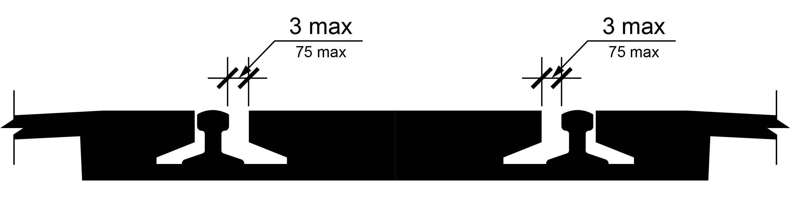
R302.6.4.2.2 Flangeway Gaps at Tracks Not Subject to FRA Safety Regulations safety regulations
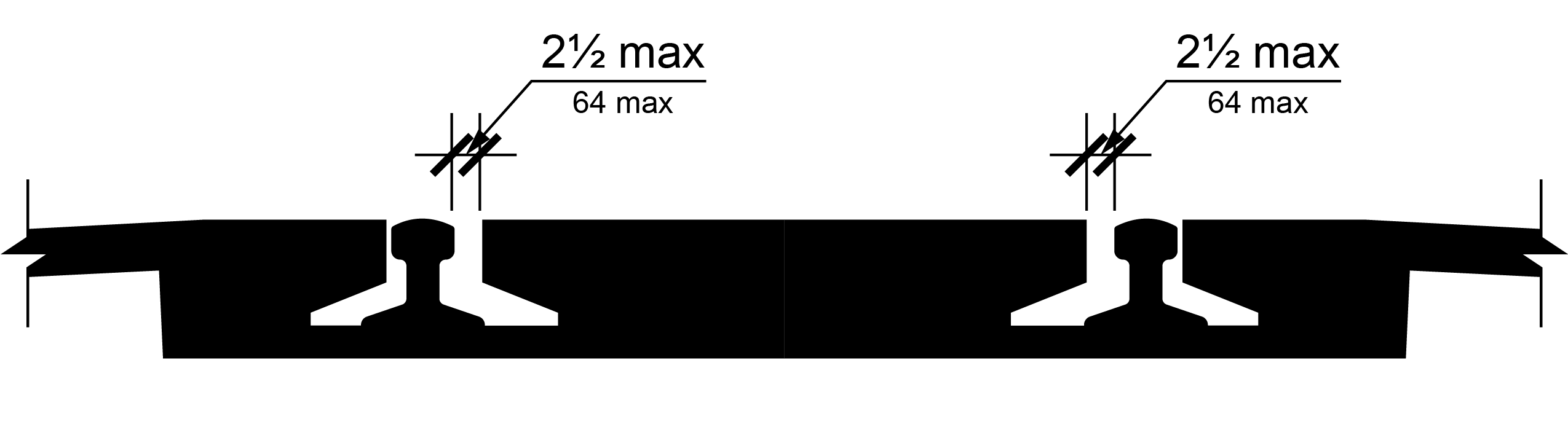
At pedestrian at-grade rail crossings that cross tracks that are not subject to safety regulations at 49 CFR part 213, issued by the Federal Railroad Administration, flangeway gaps shall be 2½ inches (64 mm) wide maximum.
R303 Alternate Pedestrian Access Routes
R303.1 General
Alternate pedestrian access routes shall comply with R303.
R303.2 Signs
Signs identifying alternate pedestrian access routes shall be provided in advance of decision points and shall comply with R410. Proximity actuated audible signs or other non-visual means within the public right-of-way of conveying the information that identifies the alternate pedestrian access route shall also be provided.
R303.3 Surface
Alternate pedestrian access route surfaces shall comply with R302.6 or shall not be less accessible than the surface of the temporarily closed pedestrian circulation path.
R303.4 Continuous Clear Width
The minimum continuous clear width of alternate pedestrian access routes shall be 48 inches (1220 mm) exclusive of the width of any curb.
EXCEPTION: Where the alternate pedestrian access route utilizes an existing pedestrian circulation path, the width shall not be less than the width of the temporarily closed pedestrian circulation path.
R303.5 Curb Ramp or Blended Transition
Where an alternate pedestrian access route crosses a curb, a curb ramp or blended transition complying with R304 shall be provided.
R303.6 Detectable Edging of Channelizing Devices
Where a channelizing device is used to delineate an alternate pedestrian access route, continuous detectable edging complying with R303.6 shall be provided throughout the length of the route.
EXCEPTION: Where pedestrians or vehicles turn or cross, gaps in the detectable edging are permitted.
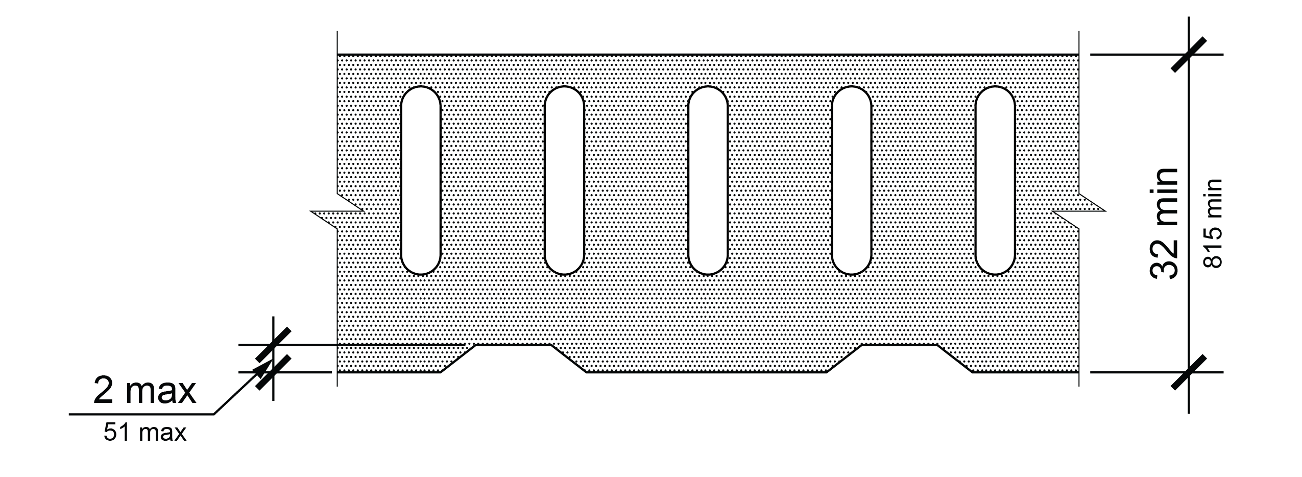
R303.6.1 Top
The top of the top detectable edging shall be no lower than 32 inches (815 mm) above the walking surface and be free of sharp or abrasive surfaces.
R303.6.2 Bottom
The bottom of the bottom detectable edging shall be 2 inches (51 mm) maximum above the walking surface.
R303.7 Pedestrian Signal Heads
Where temporary pedestrian signal heads are provided at a crosswalk that is part of an alternate pedestrian access route, pedestrian pushbuttons or passive detection devices shall be provided and shall comply with R307.
R304 Curb Ramps and Blended Transitions
R304.1 General
Curb ramps and blended transitions shall comply with R304 and have detectable warning surfaces in accordance with R205.
R304.2 Perpendicular Curb Ramps
Perpendicular curb ramps shall comply with R304.2 and R304.5.
R304.2.1 Running Slope
The running slope of a curb ramp shall be perpendicular to the curb or gutter grade break. The running slope of the curb ramp shall be 1:12 (8.3%) maximum.
EXCEPTION: Where the curb ramp length must exceed 15 feet (4.6 m) to achieve a 1:12 (8.3%) running slope, the curb ramp length shall extend at least 15 feet (4.6 m) and may have a running slope greater than 1:12 (8.3%).
R304.2.2 Cross Slope
The cross slope of a curb ramp run shall be 1:48 (2.1%) maximum.
EXCEPTION: At crosswalks, the cross slope of the curb ramp run shall be permitted to be equal to or less than the cross slope of the crosswalk as specified by R302.5.
R304.2.3 Grade Breaks
Grade breaks at the top and bottom of a curb ramp run shall be perpendicular to the direction of the curb ramp run. Grade breaks shall not be permitted on the surfaces of curb ramp runs and landings. Surface slopes that meet at grade breaks shall be flush.
R304.2.4 Clear Area
A clear area 48 inches (1220 mm) wide minimum by 48 inches long (1220 mm) minimum shall be provided beyond the bottom grade break of the perpendicular curb ramp run and within the width of the crosswalk. At shared use paths, the clear area shall be as wide as the shared use path. The clear area shall be located wholly outside the vehicle travel lanes, including bicycle lanes, that run parallel to the crosswalk. The running slope of the clear area shall be 1:20 (5.0%) maximum. The cross slope of the clear area shall be as specified by R302.5.
R304.2.5 Landing
When a change in direction is necessary to access a curb ramp from a pedestrian access route, a landing shall be provided at the top of the curb ramp. The landing shall be 48 inches (1220 mm) wide minimum by 48 inches (1220 mm) long minimum. At shared use paths, the landing shall be as wide as the shared use path. Where a landing serves only one curb ramp, the landing slope measured perpendicular to the curb ramp run shall be equal to or less than the cross slope of the curb ramp run, and the landing slope measured parallel to the curb ramp run shall be 1:48 (2.1%) maximum. Where a landing serves two curb ramps, the landing slope in either direction of travel shall not exceed the cross slope of the crosswalk parallel to the direction of travel as specified by R302.5.
R304.2.6 Side Treatments
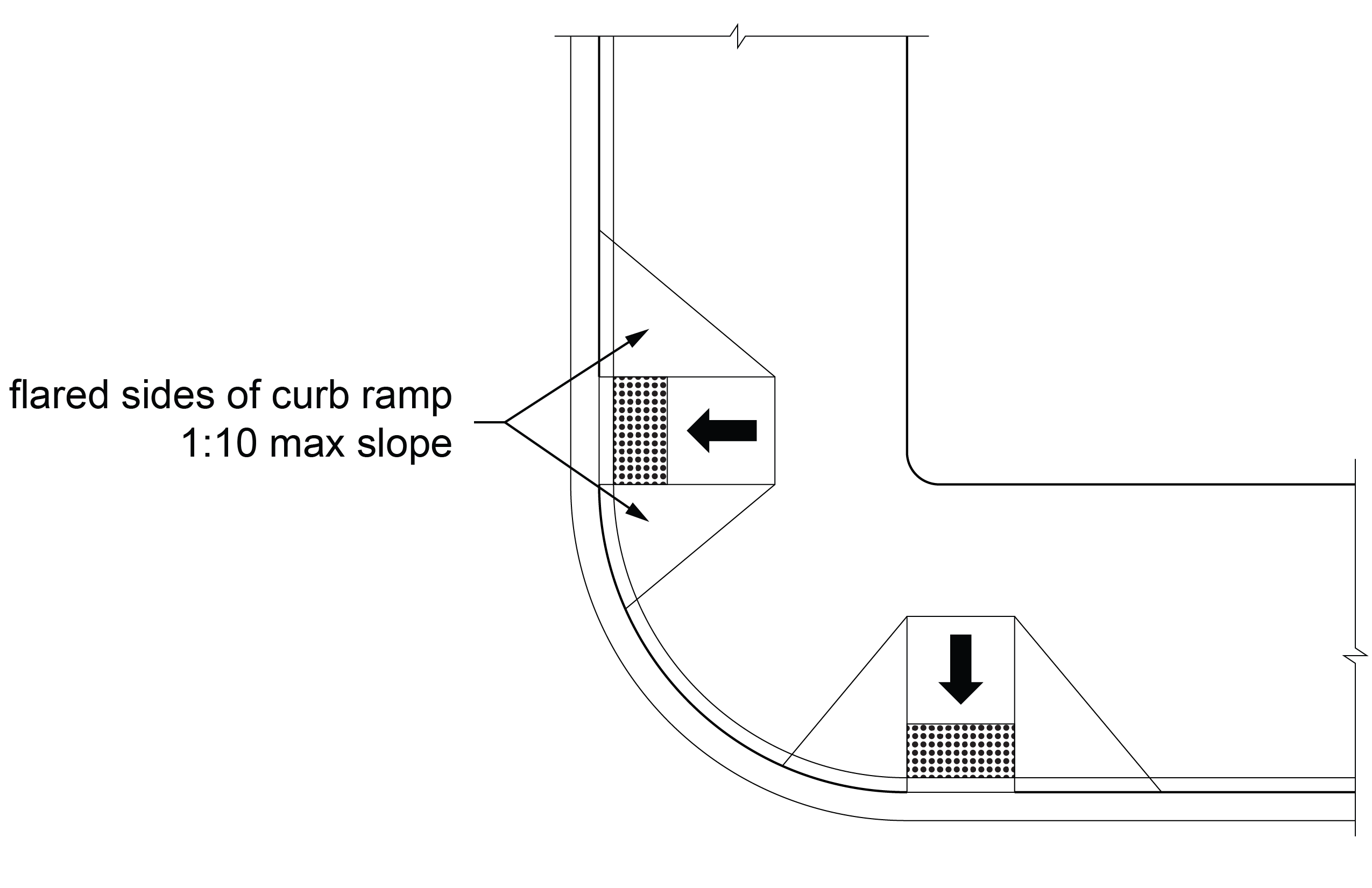
Where a pedestrian circulation path crosses the side of a curb ramp, the side of the curb ramp shall be flared. The slope of the flared side shall be 1:10 (10.0%) maximum, measured parallel to the adjacent curb line.
R304.2.7 Connection to Pedestrian Facilities
Perpendicular curb ramps or their landings shall be connected to adjacent pedestrian facilities by pedestrian access routes complying with R302. A transitional segment may be used in the connection.
R304.3 Parallel Curb Ramps
Parallel curb ramps shall comply with R304.3 and R304.5.
R304.3.1 Running Slope
The running slope of the curb ramp run shall be parallel to the curb and shall be 1:12 (8.3%) maximum.
EXCEPTION: Where the curb ramp run length must exceed 15 feet (4.6 m) to achieve a 1:12 (8.3%) running slope, the curb ramp run length shall extend at least 15 feet (4.6 m) and may have a running slope greater than 1:12 (8.3%).
R304.3.2 Cross Slope
The cross slope of the curb ramp run shall be 1:48 (2.1%) maximum.
R304.3.3 Grade Breaks
Grade breaks at the top and bottom of a curb ramp run shall be perpendicular to the direction of the curb ramp run. Grade breaks shall not be permitted on the surfaces of curb ramp runs or landings. Surface slopes that meet at grade breaks shall be flush.
R304.3.4 Landings
Landings shall be provided at the bottom of parallel curb ramps. Landings shall be 48 inches (1220 mm) wide minimum by 48 inches (1220 mm) long minimum. The slope of the landing, measured parallel to the direction of travel on the curb ramp run, shall be permitted to be equal to or less than the slope of the roadway or the cross slope of the crosswalk as specified by R302.5. The cross slope of the landing shall be 1:48 (2.1%) maximum measured perpendicular to the direction of travel on the curb ramp run.
R304.4 Blended Transitions
Blended transitions shall comply with R304.4 and R304.5.
R304.4.1 Running Slope
The running slope of blended transitions shall be 1:20 (5.0%) maximum.
R304.4.2 Cross Slope
The cross slope of blended transitions shall be equal to or less than the cross slope of the crosswalk as specified by R302.5.
R304.4.3 Bypass
Where a blended transition serving more than one pedestrian circulation path has a running slope greater than 1:48 (2.1%), a pedestrian access route shall be provided so that a pedestrian not crossing the street may bypass the blended transition.
R304.5 Common Requirements
Curb ramps and blended transitions shall comply with R304.5.
R304.5.1 Width
The width of curb ramp runs (excluding any flared sides) and blended transitions shall comply with R304.5.1.1 or R304.5.1.2, as applicable.
R304.5.1.1 Curb Ramps and Blended Transitions Not on Shared Use Paths
The clear width of curb ramp runs (excluding any flared sides) and blended transitions not on shared use paths shall be 48 inches (1220 mm) minimum.
R304.5.1.2 Curb Ramps and Blended Transitions on Shared Use Paths
On shared use paths, the width of curb ramp runs (excluding any flared sides) and blended transitions shall be equal to the width of the shared use path.
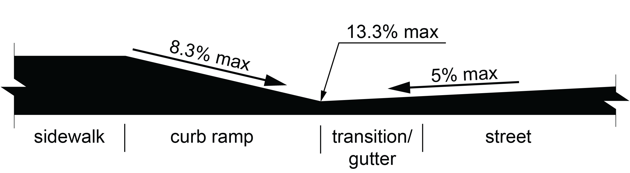
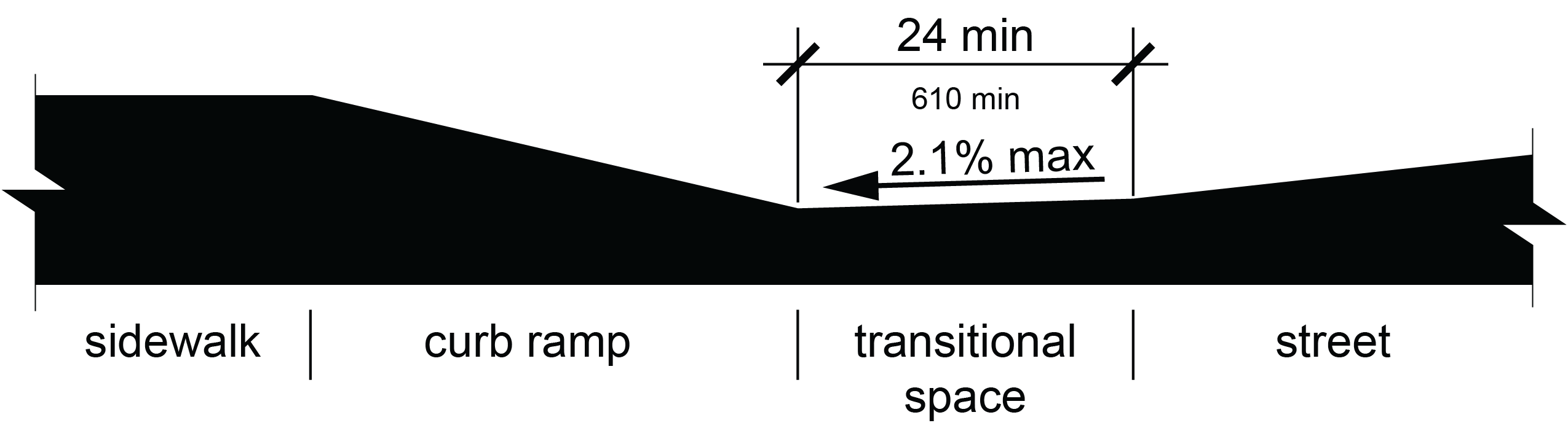
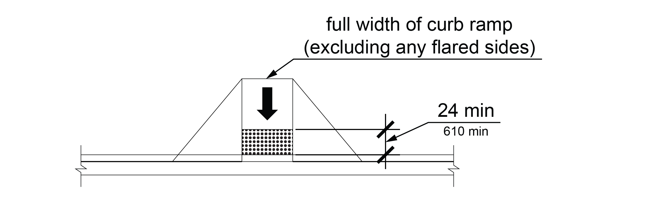
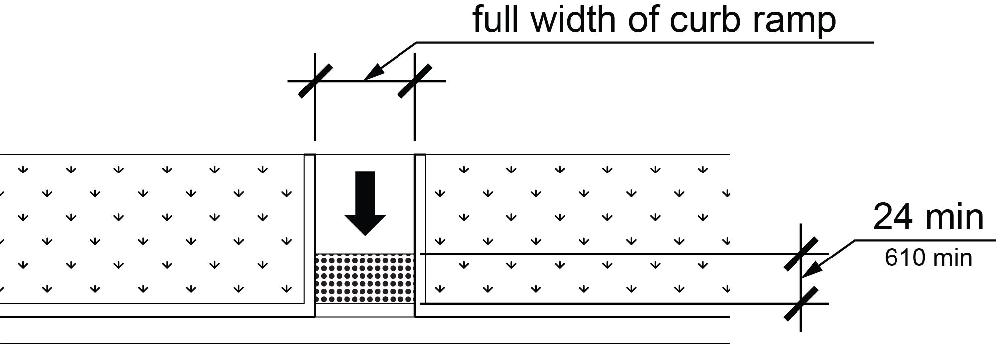
R304.5.2 Change of Grade
At gutters and streets where a change of grade occurs adjacent to curb ramps and blended transitions, the change of grade shall comply with the requirements contained in (A) or (B) below:
A. The change of grade shall not exceed 13.3 percent, or
B. A transitional space shall be provided at the bottom of the running slope of the curb ramp run or blended transition. The transitional space shall extend 24 inches (610 mm) minimum in the direction of pedestrian travel and the full width of the curb ramp run or blended transition. Transitional spaces shall have running slopes of 1:48 (2.1%) maximum and cross slopes no greater than the cross slope of the crosswalk as specified by R302.5.
R304.5.3 Crosswalks
Perpendicular curb ramp runs, parallel curb ramp landings, and 48 inches (1220 mm) minimum width of blended transitions, except those at shared use paths, shall be contained wholly within the width of the crosswalks they serve. At shared use paths, the full width of a perpendicular curb ramp run, parallel curb ramp landing, or the blended transition shall be contained wholly within the width of the crosswalk it serves.
R304.5.4 Surfaces
Surfaces of curb ramps and blended transitions shall comply with R302.6 except that changes in level are not permitted.
R305 Detectable Warning Surfaces
R305.1 General
Detectable warning surfaces shall consist of truncated domes in a square or radial grid pattern and shall comply with R305.
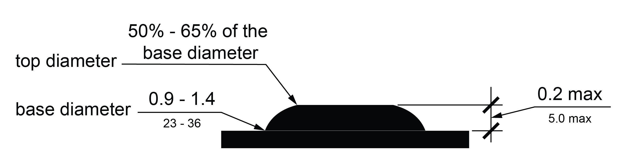
R305.1.1 Dome Size
The truncated domes shall have a base diameter of 0.9 inches (23 mm) minimum and 1.4 inches (36 mm) maximum, a top diameter of 50 percent of the base diameter minimum and 65 percent of the base diameter maximum, and a height of 0.2 inches (5.1 mm). When detectable warning surface tiles are cut to fit, partial domes are permitted along the cut edges.
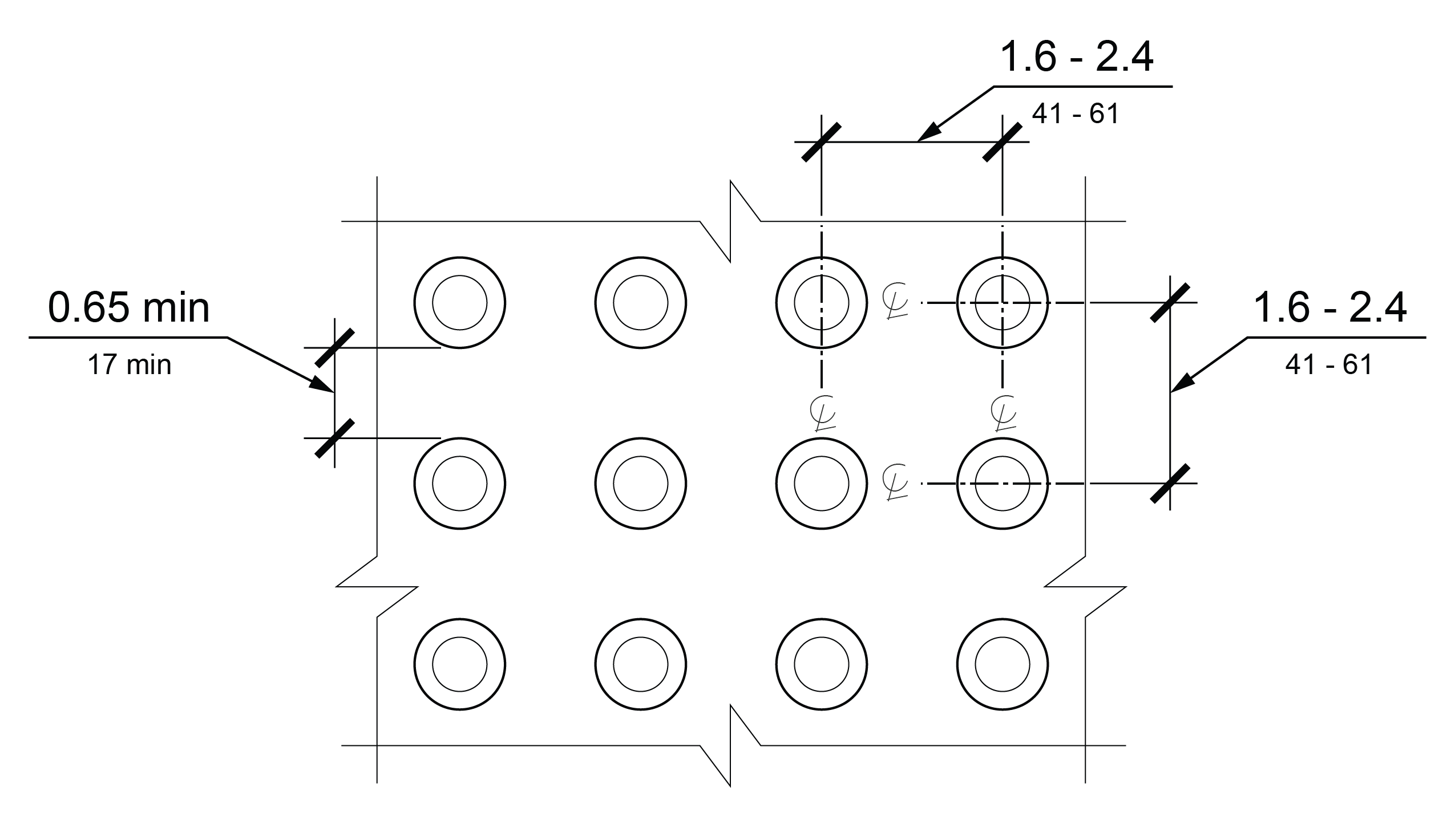
R305.1.2 Dome Spacing
The truncated domes shall have a center-to-center spacing of 1.6 inches (41 mm) minimum and 2.4 inches (61 mm) maximum, and a base-to-base spacing of 0.65 inches (17 mm) minimum, measured between the most adjacent domes.
EXCEPTIONS: 1. When detectable warning surfaces are cut to fit, center-to-center spacing measured between domes adjacent to cut edges shall not exceed twice the normal spacing between domes not adjacent to cut edges.
2. Dome spacing requirements do not apply at a gap in a detectable warning surface at an expansion joint provided that the detectable warning surface aligns with both edges of the expansion joint.
R305.1.3 Contrast
Detectable warning surfaces shall contrast visually with adjacent walking surfaces, either light-on-dark or dark-on-light.
R305.1.4 Surface Size
Detectable warning surfaces shall extend 24 inches (610 mm) minimum in the direction of pedestrian travel. The width of detectable warning surfaces shall be as follows:
A. At curb ramps and blended transitions, detectable warning surfaces shall extend the full width of the curb ramp run (excluding any flared sides), blended transition, or landing.
B. At cut-through pedestrian refuge islands, detectable warning surfaces shall extend the full width of the pedestrian circulation path opening.
C. At pedestrian at-grade rail crossings not located within a street, detectable warning surfaces shall extend the full width of the pedestrian circulation path.
D. Where required at boarding platforms, detectable warning surfaces shall extend the full length of the unprotected areas of the platform.
E. At boarding and alighting areas at sidewalk or street level transit stops for rail vehicles, detectable warning surfaces shall extend the full length of the unprotected area of the transit stop.
R305.2 Location
The location of detectable warning surfaces shall comply with R305.2. Where a concrete border is required for proper installation of a detectable warning surface, a concrete border not exceeding 2 inches (51 mm) shall be permitted on all sides of the detectable warning surface except between the detectable warning surface and the edge of pavement where a setback is already permitted.
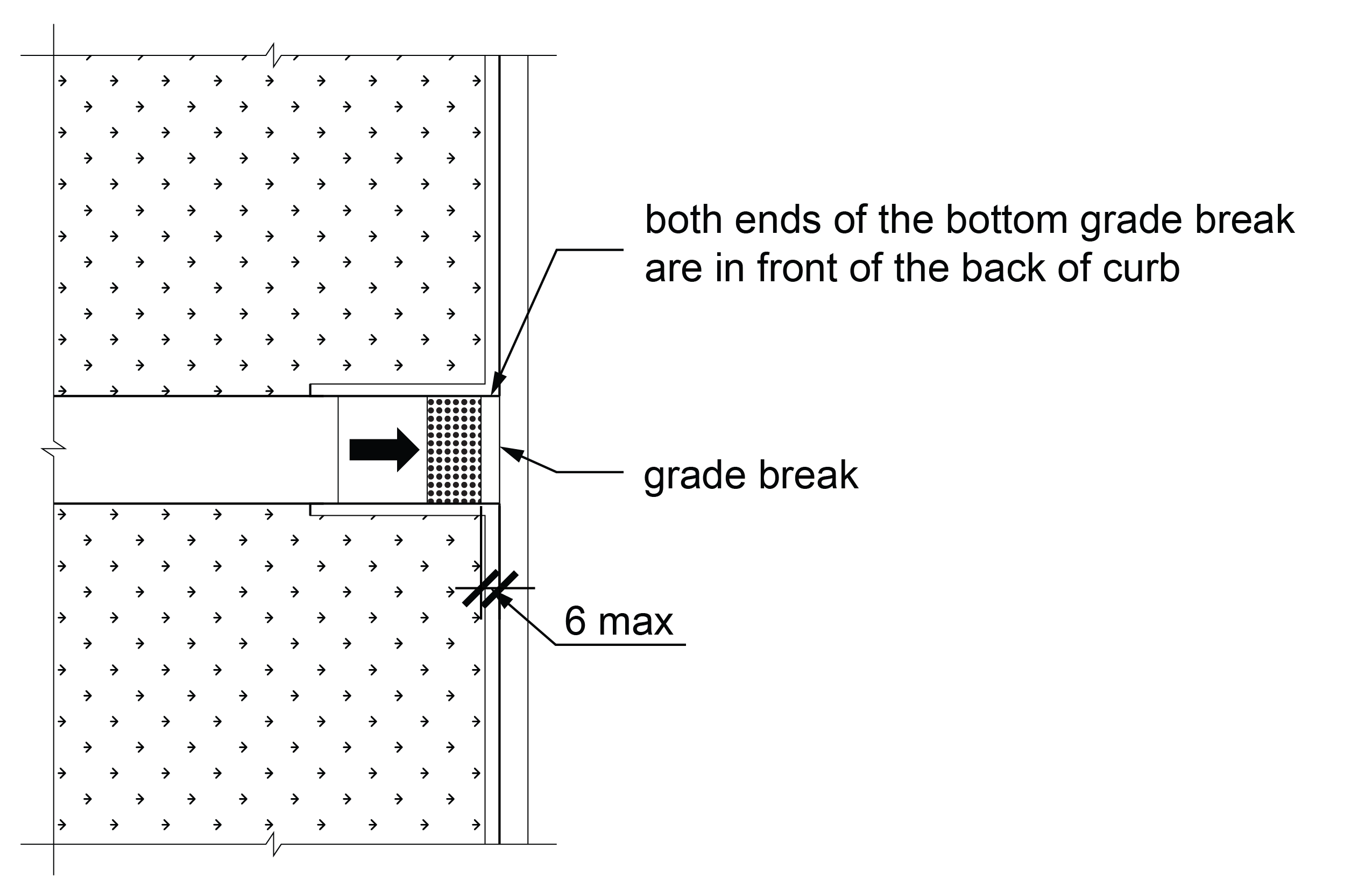
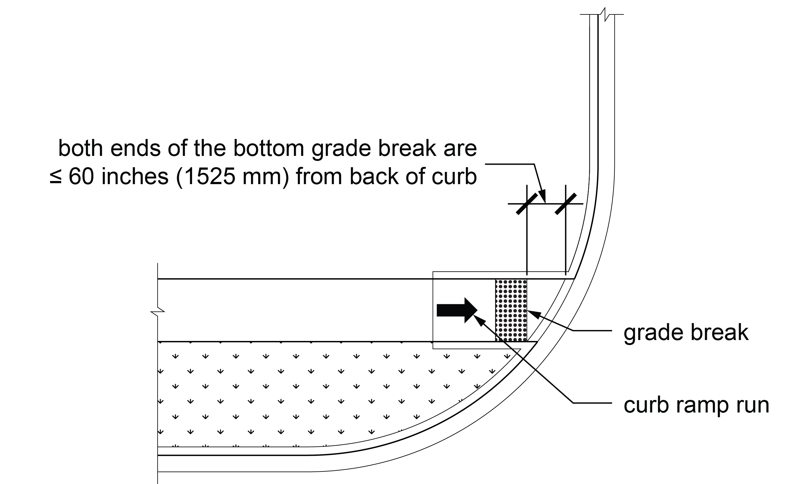
R305.2.1 Perpendicular Curb Ramps
On perpendicular curb ramps, detectable warning surfaces shall be located as follows:
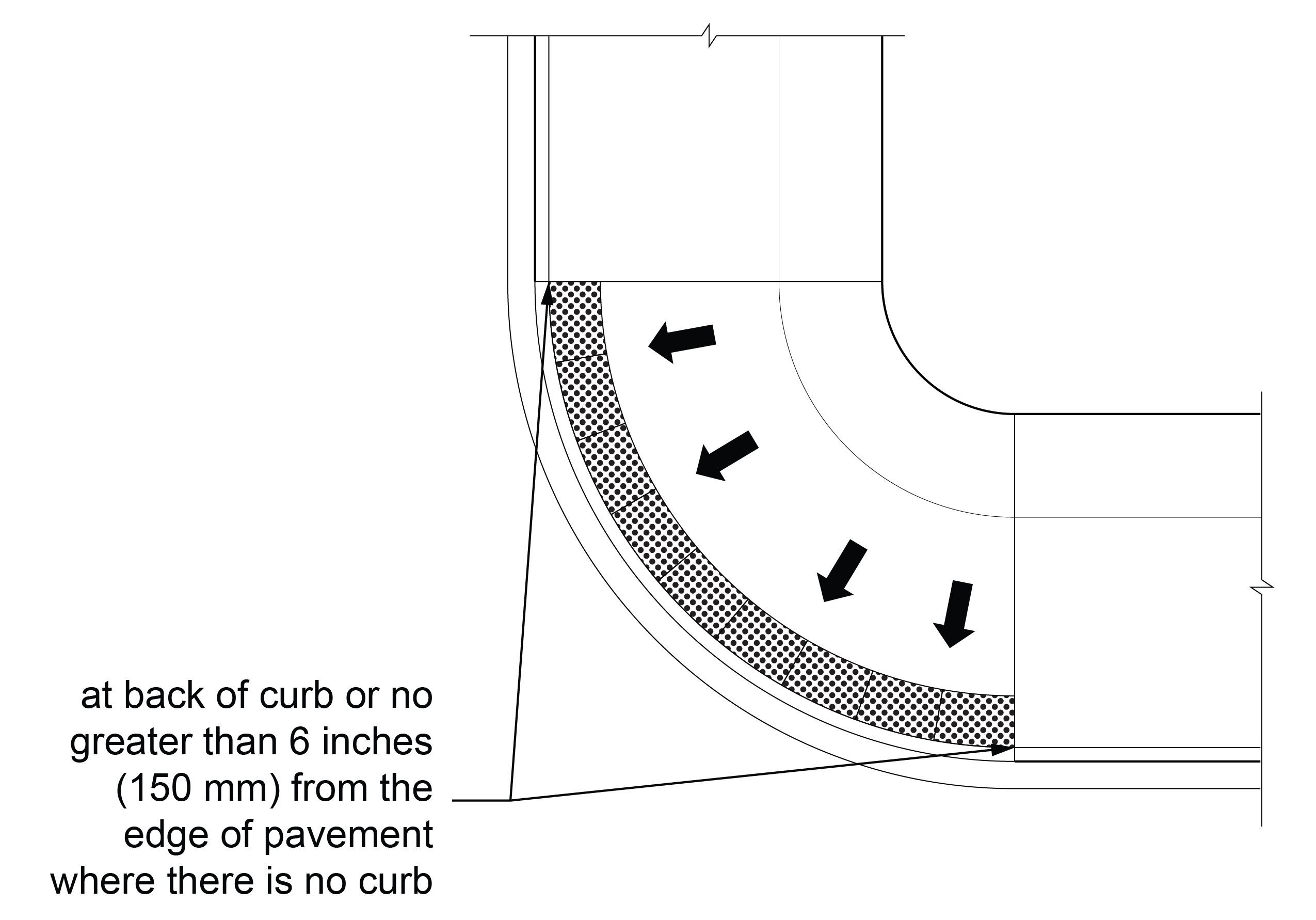
A. Where the ends of the bottom grade break are in front of the back of curb or at the edge of pavement where there is no curb, the detectable warning surface shall be placed at the back of curb or no greater than 6 inches (150 mm) from the edge of pavement where there is no curb.
B. Where the ends of the bottom grade break are behind the back of curb or edge of pavement where there is no curb and the distance from both ends of the bottom grade break to the back of curb or edge of pavement where there is no curb is 60 inches (1525 mm) or less, the detectable warning surface shall be placed on the ramp run at the bottom grade break.
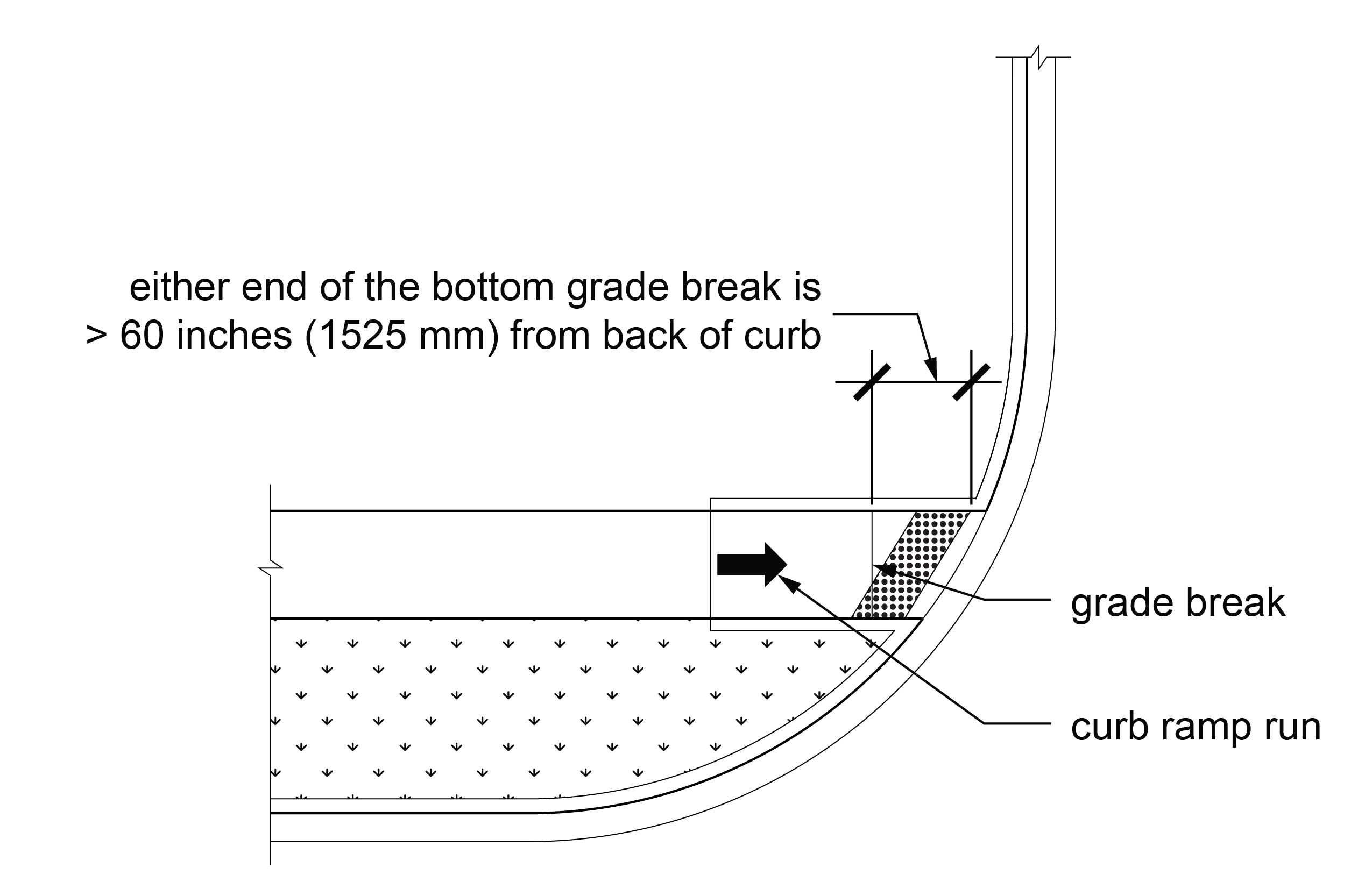
C. Where the ends of the bottom grade break are behind the back of curb or edge of pavement where there is no curb and the distance from either end of the bottom grade break to the back of curb or edge of pavement where there is no curb is more than 60 inches (1525 mm), the detectable warning surface shall be placed on the clear area so that both front corners of the detectable warning surfaces are at the back of curb or no greater than 6 inches (150 mm) from the edge of pavement where there is no curb.
R305.2.2 Parallel Curb Ramps
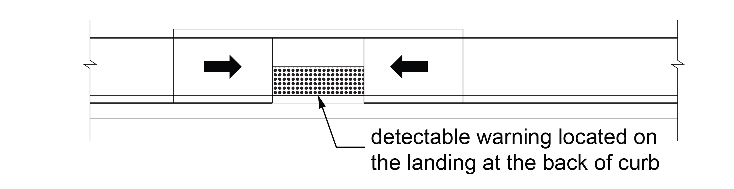
On parallel curb ramps, detectable warning surfaces shall be located on the landing at either the back of curb or the edge of pavement where there is no curb.
R305.2.3 Blended Transitions
On blended transitions, detectable warning surfaces shall be located on the blended transition so that both front corners of the detectable warning surfaces are at the back of curb or no greater than 6 inches (150 mm) from the edge pavement where there is no curb.
R305.2.4 Pedestrian Refuge Islands
At cut-through pedestrian refuge islands, detectable warning surfaces shall be located no greater than 6 inches (150 mm) from the edges of the pedestrian refuge island or at back of curb and shall be separated by a 24 inch (610 mm) minimum length of surface in the direction of travel without detectable warning surfaces.
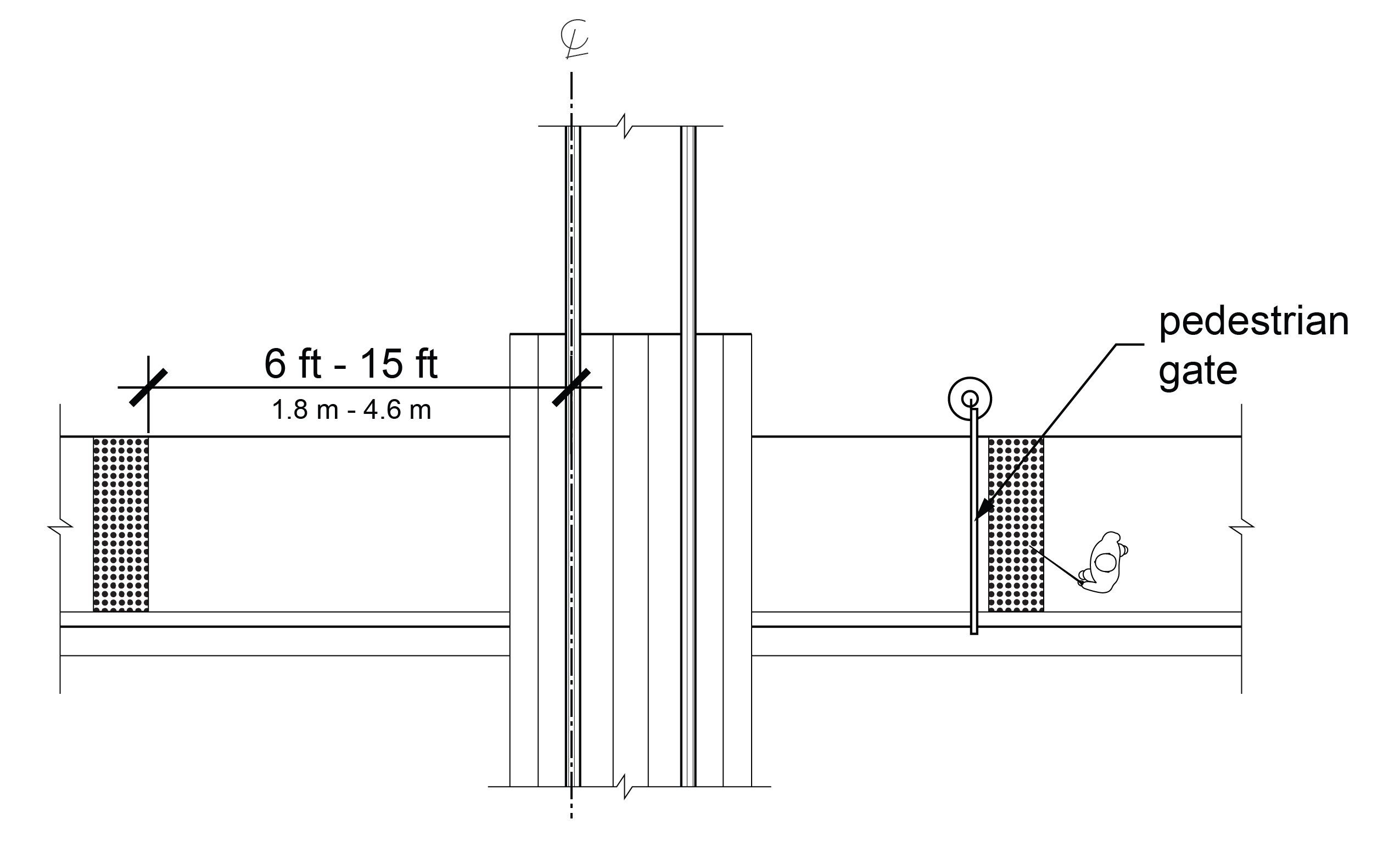
R305.2.5 Pedestrian At-Grade Rail Crossings
At pedestrian at-grade rail crossings not located within a street, detectable warning surfaces shall be located on each side of the rail crossing. The edge of the detectable warning surface nearest the rail crossing shall be 6 feet (1.8 m) minimum and 15 feet (4.6 m) maximum from the centerline of the nearest rail. Where pedestrian gates are provided, detectable warning surfaces shall be located on the side of the gate opposite the rail. Pedestrian gates shall not overlap detectable warning surfaces.
R305.2.6 Boarding Platforms
At boarding platforms for transit vehicles, detectable warning surfaces shall be located at the boarding edge of the platform.
EXCEPTION: Where a curb is present at the boarding edge of the platform, the detectable warning surface may be placed at the back of curb.
R305.2.7 Sidewalk and Street-Level Rail Boarding and Alighting Areas
At boarding and alighting areas at sidewalk or street-level transit stops for rail vehicles, detectable warning surfaces shall be located at the edge of the boarding and alighting area closest to the rail vehicles.
R305.2.8 Driveways
Where driveways are controlled with yield or stop control devices or traffic signals, detectable warning surfaces shall be provided on the pedestrian circulation path where the pedestrian circulation path meets the driveway.
R306 Crosswalks
R306.1 General
Crosswalks shall comply with R306.
R306.2 Pedestrian Signal Phase Timing
Where a traffic control signal with pedestrian signal indications is provided at a crosswalk, pedestrian signal phase timing shall be based on a pedestrian clearance time that is calculated using a pedestrian walking speed of 3.5 ft/s (1.1 m/s) or less from the location of the pedestrian push button to a pedestrian refuge island or the far side of the traveled way. The walk interval shall be 7 seconds minimum. Where the pedestrian clearance time is calculated to a pedestrian refuge island, an additional pedestrian push button or passive detection device shall be provided on the pedestrian refuge island.
EXCEPTION: If a passive pedestrian detection device is used to automatically adjust the pedestrian clearance time based on the pedestrian’s actual clearance of the crosswalk, a faster walking speed may be used.
R306.3 Accessible Walk Indication
An accessible walk indication complying with R308.2 shall have the same duration as the walk interval.
EXCEPTION: Where the pedestrian signal rests in walk, the accessible walk indication may be limited to the first 7 seconds of the walk interval. If the pedestrian signal is resting in walk and there is sufficient time remaining to provide an accessible walk interval before the beginning of the pedestrian change interval, the accessible walk indication may be recalled by a button press.
R306.4 Roundabouts
Where pedestrian circulation paths are provided at roundabouts, they shall comply with R306.4.
R306.4.1 Edge Detection
The street side edge of the pedestrian circulation path at the approach and along the circulatory roadway of the roundabout shall comply with R306.4.1.1 where not attached to the curb, or R306.4.1.2 where attached to the curb. Detectable warning surfaces shall not be used for roundabout edge detection.
R306.4.1.1 Separation
Where pedestrian crossing is not intended, the pedestrian circulation path shall be separated from the curb, crosswalk to crosswalk, with landscaping or other nonprepared surface 24 inches (610 mm) wide minimum.
R306.4.1.2 Vertical Edge Treatment
Where pedestrian crossing is not intended, a curb-attached pedestrian circulation path shall have a continuous and detectable vertical edge treatment along the street side of the pedestrian circulation path, from crosswalk to crosswalk. The bottom edge of the vertical edge treatment shall be 15 inches (380 mm) maximum above the pedestrian circulation path.
R306.4.2 Crosswalk Treatments
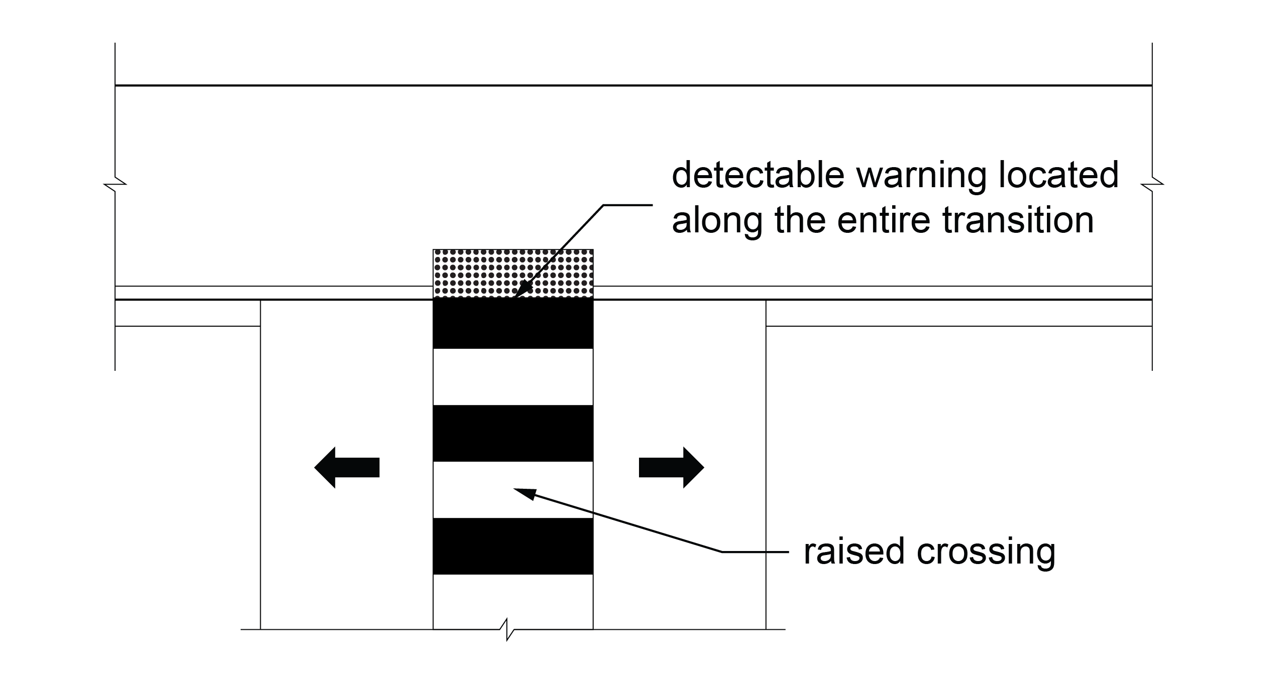
Each multi-lane segment of the roundabout containing a crosswalk shall provide a crosswalk treatment consisting of one or more of the following: a traffic control signal with a pedestrian signal head; a pedestrian hybrid beacon; a pedestrian actuated rectangular rapid flashing beacon; or a raised crossing.
R306.5 Channelized Turn Lanes
Crosswalks at multi-lane channelized turn lanes shall provide treatments consisting of one or more of the following: a traffic control signal with a pedestrian signal head; a pedestrian hybrid beacon; a pedestrian actuated rectangular rapid flashing beacon; or a raised crossing.
R307 Pedestrian Push Buttons and Passive Pedestrian Detection
R307.1 General
Pedestrian push buttons and passive pedestrian detection devices shall comply with R307. Operable parts of pedestrian push buttons shall comply with R403.
R307.2 Activation
Pedestrian push buttons and passive detection devices shall activate the accessible pedestrian signals and, where applicable, the walk interval.
R307.3 Extended Push Button Press
Where an extended push button press is used to provide any additional features, a push button press of less than one second shall actuate only the pedestrian timing and any associated accessible walk indication, and a push button press of one second or more shall actuate the pedestrian timing, any associated accessible walk indication, and any additional features. If additional crossing time is provided by means of an extended pushbutton press, a sign so indicating shall be mounted adjacent to or integral with the pedestrian push button.
R307.4 Location
Pedestrian push buttons shall be located no greater than 5 feet from the side of a curb ramp run or the edge of the farthest associated crosswalk line from the center of the intersection. Pedestrian push buttons shall be located between 1.5 and 10 feet from the edge of the curb or pavement.
R307.4.1 Two Pedestrian Push Buttons on Same Corner
Where two pedestrian push buttons are provided on the same corner, they shall be 10 feet or more apart.
EXCEPTION: In alterations, where technically infeasible to provide 10 feet separation between pedestrian push buttons on the same corner, a pedestrian push button information message complying with R308.3.2 shall be provided.
R307.5 Push Button Orientation
The face of the push button shall be parallel to its associated crosswalk.
R307.6 Audible and Vibrotactile Walk Indications for Pedestrian Signal Heads
Pedestrian push buttons or passive detection devices shall activate audible and vibrotactile walk indications complying with R308.
R307.7 Audible and Vibrotactile Indication for Pedestrian Activated Warning Devices Without a Walk Indication
Where a pedestrian push button or a passive detection device is provided for pedestrian activated warning devices, such as rectangular rapid flashing beacons, the pedestrian push button or passive detection device shall activate a speech message that indicates the status of the beacon in lieu of an audible walk indication. The speech message volume shall comply with R308.4. Where a pedestrian push button is provided, it shall not include vibrotactile features indicating a walk interval.
R307.8 Locator Tone
Pedestrian push buttons shall incorporate a locator tone complying with R307.8.
R307.8.1 Duration
Locator tones shall have a duration of 0.15 seconds or less and repeat at one-second intervals except when another audible indication from the same device is active. When another audible indication from the same device is active, the locator tone shall be silenced.
EXCEPTION: A locator tone may be silenced if a passive detection system activates the locator tone when a pedestrian is within a 12-foot radius of the pedestrian push button.
R307.8.2 Locator Tone in Response to Ambient Sound
Pedestrian push button locator tones shall be intensity responsive to ambient sound and shall be audible 6 to 12 feet from the push button, or to the building line, whichever is less. The push button locator tone shall be louder than ambient sound up to a maximum volume of 5 dBA louder than ambient sound. Automatic volume adjustment in response to ambient traffic sound level shall be a maximum volume of 100 dBA.
R307.8.3 Locator Tone and Audible Beaconing
Where audible beaconing is used, the volume of the push button locator tone during the pedestrian change interval of the called pedestrian phase shall be increased and operated in one of the following ways:
A. The louder audible walk indication and louder locator tone comes from the far end of the crosswalk, as pedestrians cross the street;
B. The louder locator tone comes from both ends of the crosswalk; or
C. The louder locator tone comes from an additional speaker that is aimed at the center of the crosswalk and that is mounted on a pedestrian signal head.
R307.8.4 Locator Tone and Traffic Control Signal in Flashing Mode
When the traffic control signal is operating in a flashing mode, pedestrian push button locator tones shall remain active, and the pedestrian push button shall activate a speech message that communicates the operating mode of the traffic control signal. Where traffic control signals or pedestrian hybrid beacons are activated from a flashing or dark mode to a stop-and-go mode by pedestrian actuations, a speech message communicating the operating status of the traffic control signal is not required.
R307.9 Tactile Arrow
Pedestrian push buttons shall have a tactile arrow with high visual contrast that is aligned parallel to the direction of travel on their associated crosswalks.
R308 Accessible Pedestrian Signal Walk Indications
R308.1 General
Accessible pedestrian signal walk indications shall comply with R308.
R308.2 Audible and Vibrotactile Walk Indications
Accessible pedestrian signals shall have an audible and vibrotactile walk indication during the walk interval only. The audible walk indication shall be audible from the beginning of the associated crosswalk. Following the audible and vibrotactile walk indication and during the pedestrian change interval, accessible pedestrian signals shall revert to the pedestrian push button locator tone.
R308.3 Audible Walk Indications
Audible walk indications shall comply with R308.3.
R308.3.1 Percussive Tone
Where an accessible pedestrian signal is provided at a single crossing or where two accessible pedestrian signals are 10 feet or greater from each other at a corner, the audible walk indication shall be a percussive tone and repeat eight to ten ticks per second with multiple frequencies and a dominant component at 880 Hz.
R308.3.2 Speech Walk Message
In alterations, where it is technically infeasible to provide 10 feet separation between pedestrian push buttons on the same corner, the audible walk indication for each signal shall be a speech walk message that complies with R308.3.2.
R308.3.2.1 Speech Information Message when Walk Interval is Not Timing
Where speech push button information messages are made available at a pretimed signal or by actuating the accessible pedestrian push button or passive detection device, they shall only be actuated when the walk interval is not timing. They shall begin with the term “Wait,” followed by intersection identification information modeled after: “Wait to cross Broadway at Grand.” If information on intersection signalization or geometry is also given, it shall follow the intersection identification information.
R308.3.2.2 Speech Walk Message during Pedestrian Phasing Concurrent with Vehicular Phasing
Speech walk messages that are used at intersections having pedestrian phasing that is concurrent with vehicular phasing shall be patterned after the model: “Broadway. Walk sign is on to cross Broadway.”
R308.3.2.3 Speech Walk Message during Exclusive Pedestrian Phasing
Speech walk messages that are used at intersections having exclusive pedestrian phasing shall be patterned after the model: “Walk sign is on for all crossings.”
R308.3.2.4 Speech Walk Message and Pilot Light
If a pilot light is used at an accessible pedestrian signal location, each actuation shall be accompanied by the speech message, “Wait.”
R308.4 Volume
Audible walk indications shall be louder than ambient sound up to a maximum volume of 5 dBA louder than ambient sound. Automatic volume adjustment in response to ambient traffic sound level shall be a maximum volume of 100 dBA.
EXCEPTION: Where audible beaconing is provided in response to an extended push button press, the beaconing can exceed 5 dBA louder than ambient sound.
R308.5 Vibrotactile Walk Indication
The pedestrian push button shall vibrate during the walk interval.
R309 Transit Stops and Transit Shelters
R309.1 Transit Stops
Transit stops shall comply with R309.1.
R309.1.1 Boarding and Alighting Areas
Boarding and alighting areas at sidewalk or street-level transit stops must serve each accessible vehicle entry and exit and shall comply with R309.1.1 and R309.1.3.
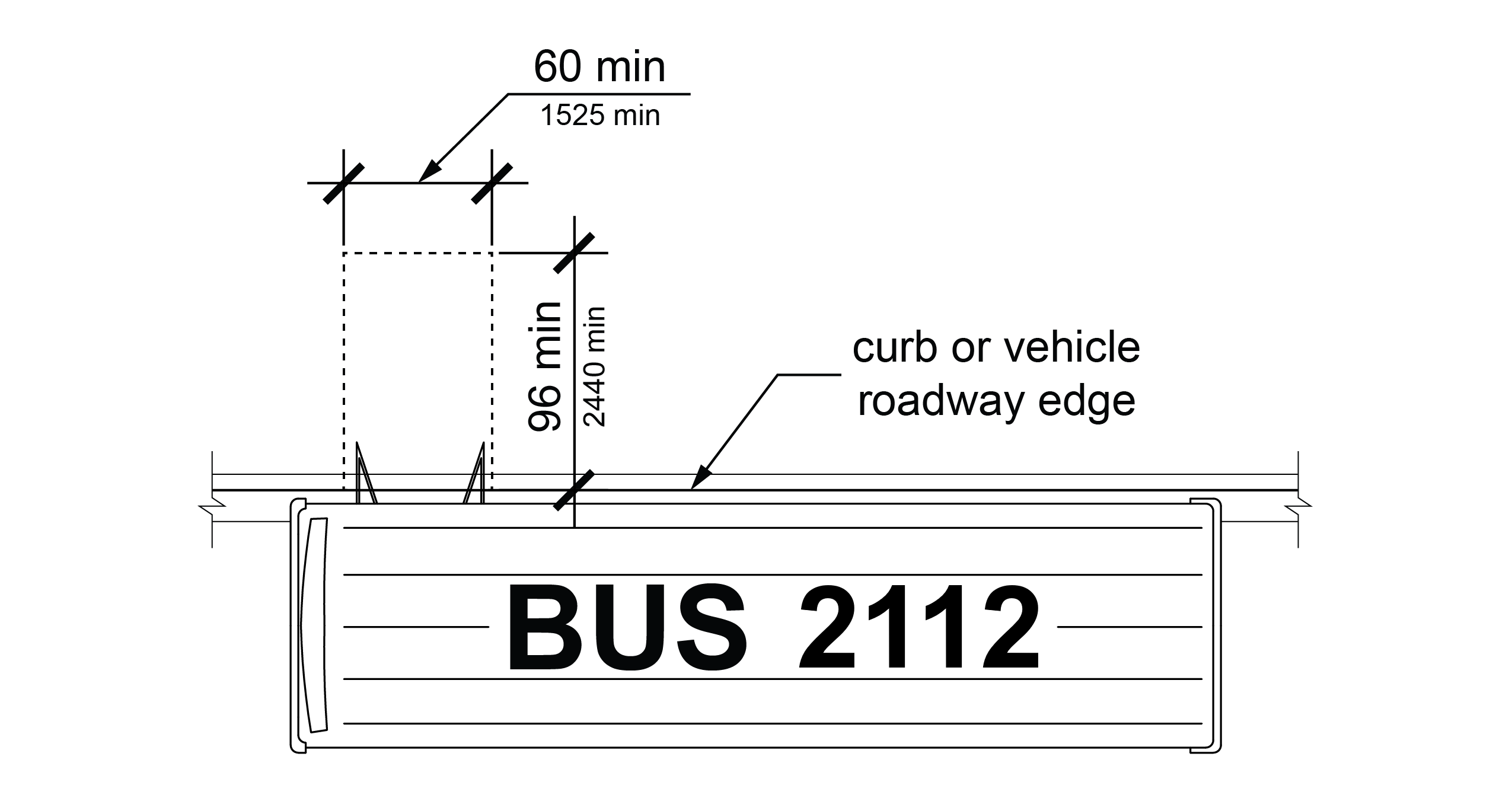
R309.1.1.1 Dimensions
Boarding and alighting areas shall have a clear length of 96 inches (2440 mm) minimum, measured perpendicular to the face of the curb or street edge, and a clear width of 60 inches (1525 mm) minimum, measured parallel to the street.
R309.1.1.2 Slope
The slope of boarding and alighting areas measured parallel to the street shall be the same as the grade of the street. The slope of boarding and alighting areas measured perpendicular to the street shall be 1:48 (2.1%) maximum.
R309.1.2 Boarding Platforms
Boarding platforms at transit stops shall comply with R309.1.2 and R309.1.3.
R309.1.2.1 Platform and Vehicle Floor Coordination
Boarding platforms shall be positioned to coordinate with vehicles in accordance with the applicable requirements in 49 CFR parts 37 and 38.
R309.1.2.2 Slope
The slope of the boarding platform measured parallel to the track or street shall be the same as the grade of the track or street. The slope of the boarding platform measured perpendicular to the track or street shall be 1:48 (2.1%) maximum.
R309.1.3 Common Requirements
Boarding and alighting areas and boarding platforms shall comply with R309.1.3.
R309.1.3.1 Surfaces
The surfaces of boarding and alighting areas and boarding platforms shall comply with R302.6.
R309.1.3.2 Connection to Existing Pedestrian Circulation Paths
In alterations, boarding and alighting areas and boarding platforms shall be connected to existing pedestrian circulation paths by pedestrian access routes complying with R302.
R309.2 Transit Shelters
Transit shelters shall comply with R309.2.
R309.2.1 Connection to Boarding and Alighting Areas
Transit shelters shall be connected by pedestrian access routes complying with R302 to boarding and alighting areas complying with R309.1.1 or boarding platforms complying with R309.1.2.
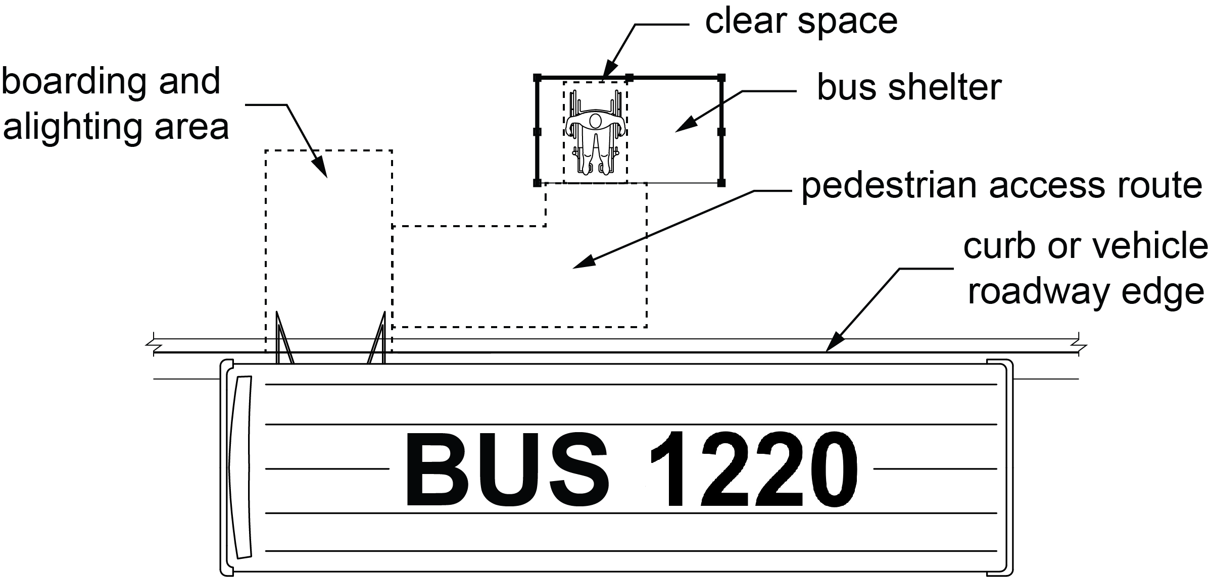
R309.2.2 Clear Space
Transit shelters shall provide a minimum clear space complying with R404 entirely within the shelter. Where seating is provided within transit shelters, the clear space shall be located either at one end of a seat or so as to not overlap the area within 18 inches (455 mm) from the front edge of the seat.
R309.2.3 Environmental Controls
Where provided, environmental controls within transit shelters shall be proximity-actuated.
R309.2.4 Protruding Objects
Protruding objects within transit shelters shall comply with R402.
R310 On-Street Parking Spaces
R310.1 General
On-street parking spaces shall comply with R310.
R310.2 Parallel On-Street Parking Spaces
Parallel on-street parking spaces shall comply with R310.2.
R310.2.1 Dimensions
Parallel on-street parking spaces shall be 24 feet (7.3 m) long minimum and 13 feet (4.0 m) wide minimum. Parallel on-street parking spaces shall not encroach on the traveled way.
EXCEPTIONS: 1. Where parallel on-street parking spaces are altered but the adjacent pedestrian circulation path is not, any accessible parallel on-street parking spaces provided may have the same dimensions as the adjacent parallel on-street parking spaces if they are provided nearest the crosswalk at the end of the block face or nearest a midblock crosswalk, and a curb ramp or blended transition is provided serving the crosswalk.
2. In alterations, where providing parallel on-street parking spaces with the dimensions specified in R310.2.1 would result in an available right-of-way width less than or equal to 9 feet (2.7 m), measured from the curb line to the right-of-way line, the accessible parallel on-street parking spaces may have the same dimensions as the adjacent parallel on-street parking spaces if they are provided nearest the crosswalk at the end of the block face or nearest a midblock crosswalk, and a curb ramp or blended transition is provided serving the crosswalk.
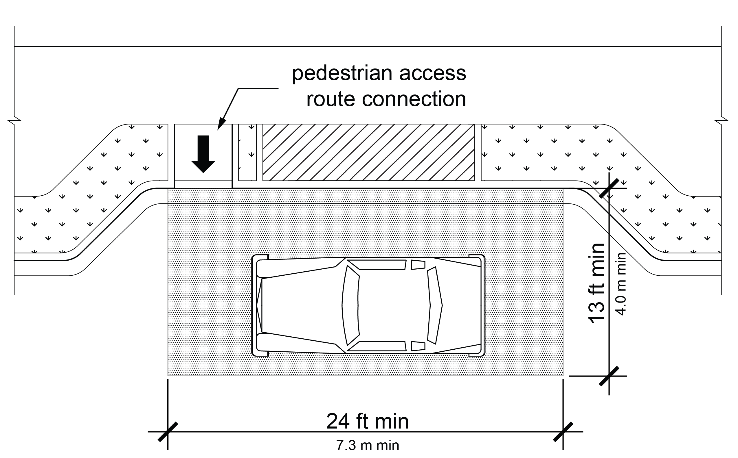
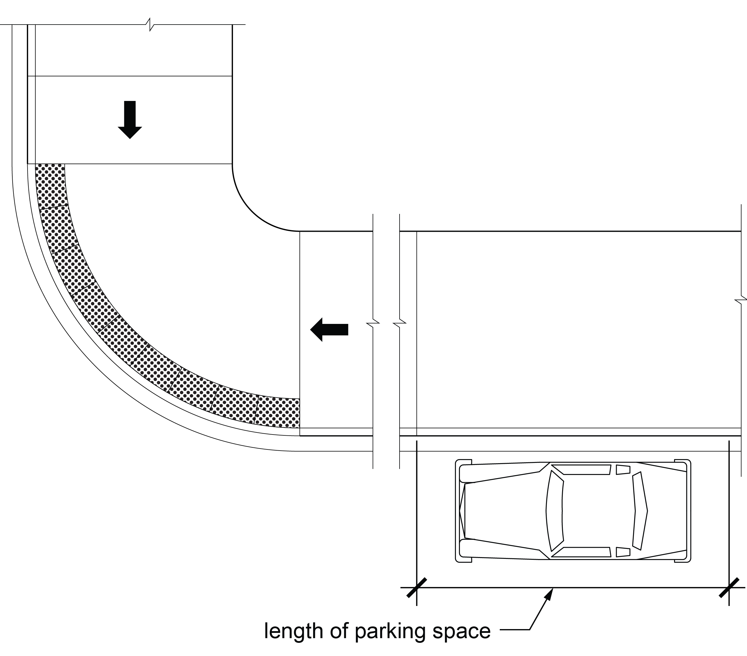
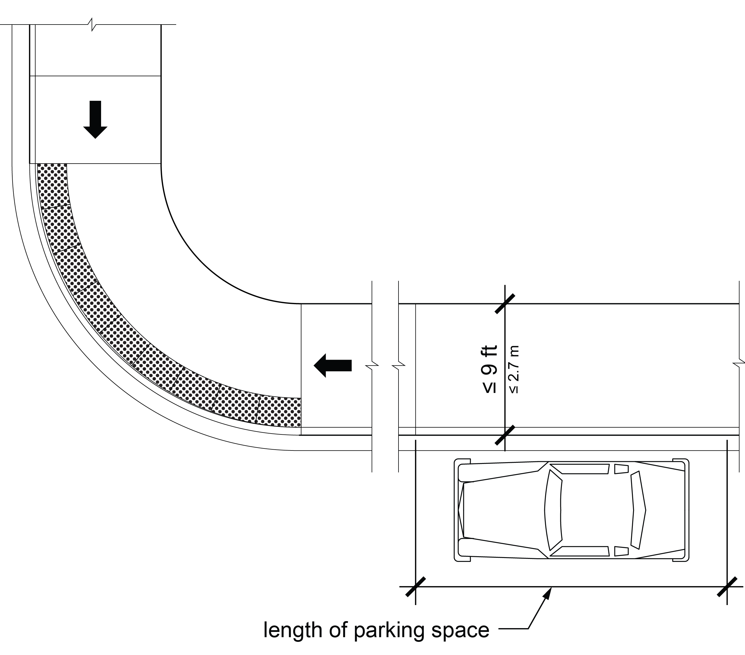
R310.2.2 Pedestrian Access Route Connection
Parallel on-street parking spaces shall connect to pedestrian access routes. Where curb ramps and blended transitions are used, they shall not reduce the required width or length of the parking spaces and shall be located at either end of the parking space. Where two or more accessible parallel on-street parking spaces complying with the dimensions specified in R310.2.1 are contiguous on a block face, each accessible parallel on-street parking space shall have an independent connection to the pedestrian access route. Curb ramps and blended transitions shall be provided in accordance with R203.6.1.3 and shall comply with R304. Detectable warning surfaces are not required on curb ramps and blended transitions used exclusively to connect accessible on-street parallel parking spaces to pedestrian access routes.
EXCEPTION: In alterations, where parallel on-street parking spaces are provided in accordance with Exception 1 or 2 to R310.2.1, the parallel on-street parking space shall be connected to the curb ramp or blended transition serving the crosswalk by a pedestrian circulation path complying with R302.6, except that changes in level are not permitted.
R310.2.3 Surfaces
Surfaces of parking spaces shall comply with R302.6, except that changes in level are not permitted.
R310.2.4 Clearance Adjacent to Parking Spaces
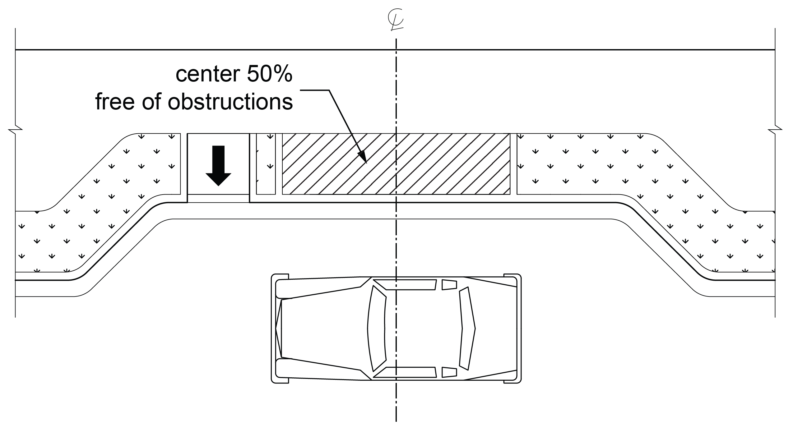
The center 50 percent of the length of the sidewalk, or other surface, adjacent to an accessible parallel parking space shall be free of obstructions, including parking identification signs, parking pay meters, and parking pay stations, and shall comply with R302.6.
R310.2.5 Identification
Parallel on-street parking spaces shall be identified by signs displaying the International Symbol of Accessibility complying with R411. Signs shall be 60 inches (1525 mm) minimum above the ground surface measured to the bottom of the sign.
R310.3 Perpendicular Parking Spaces
Perpendicular parking spaces shall comply with R310.3.
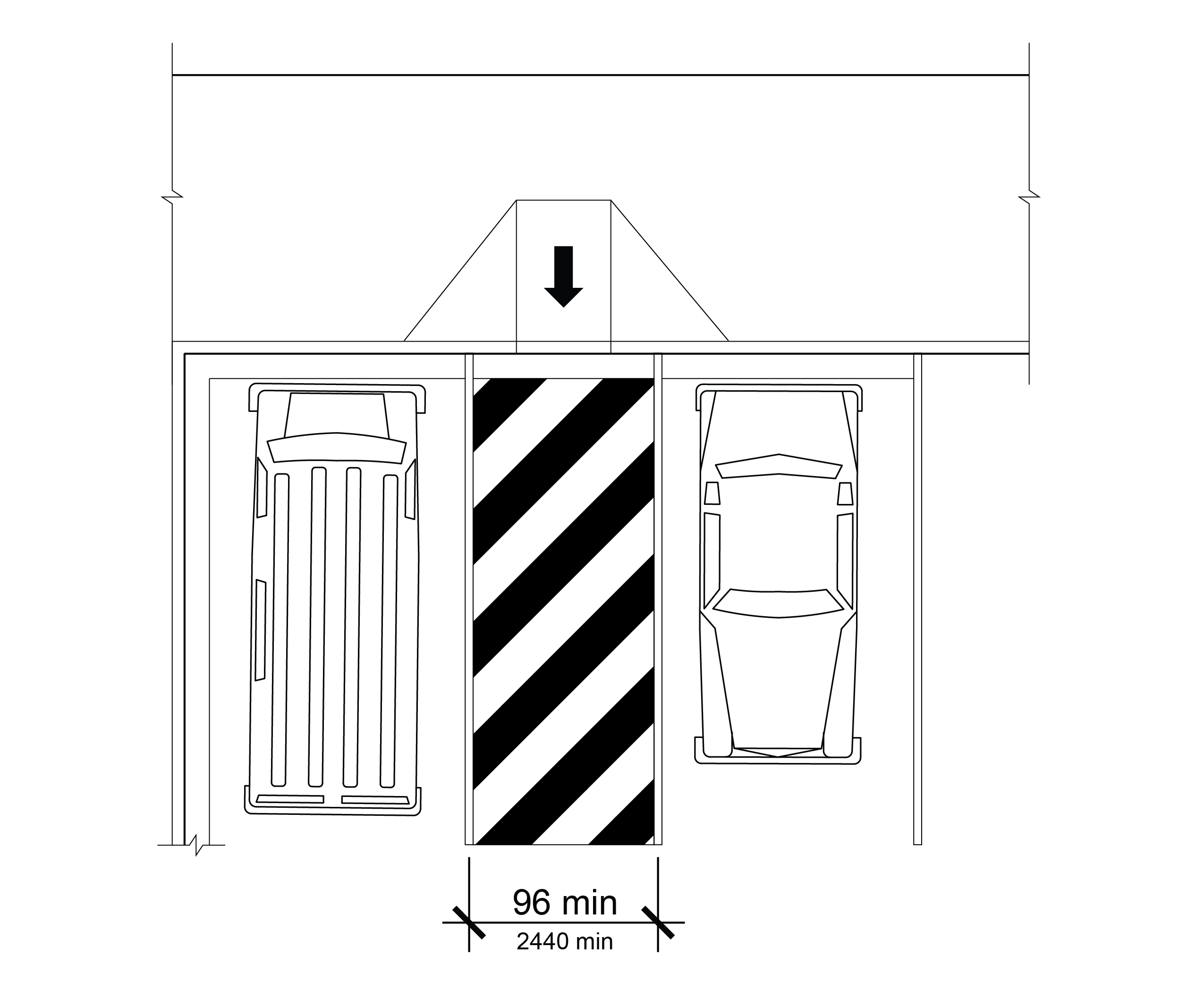
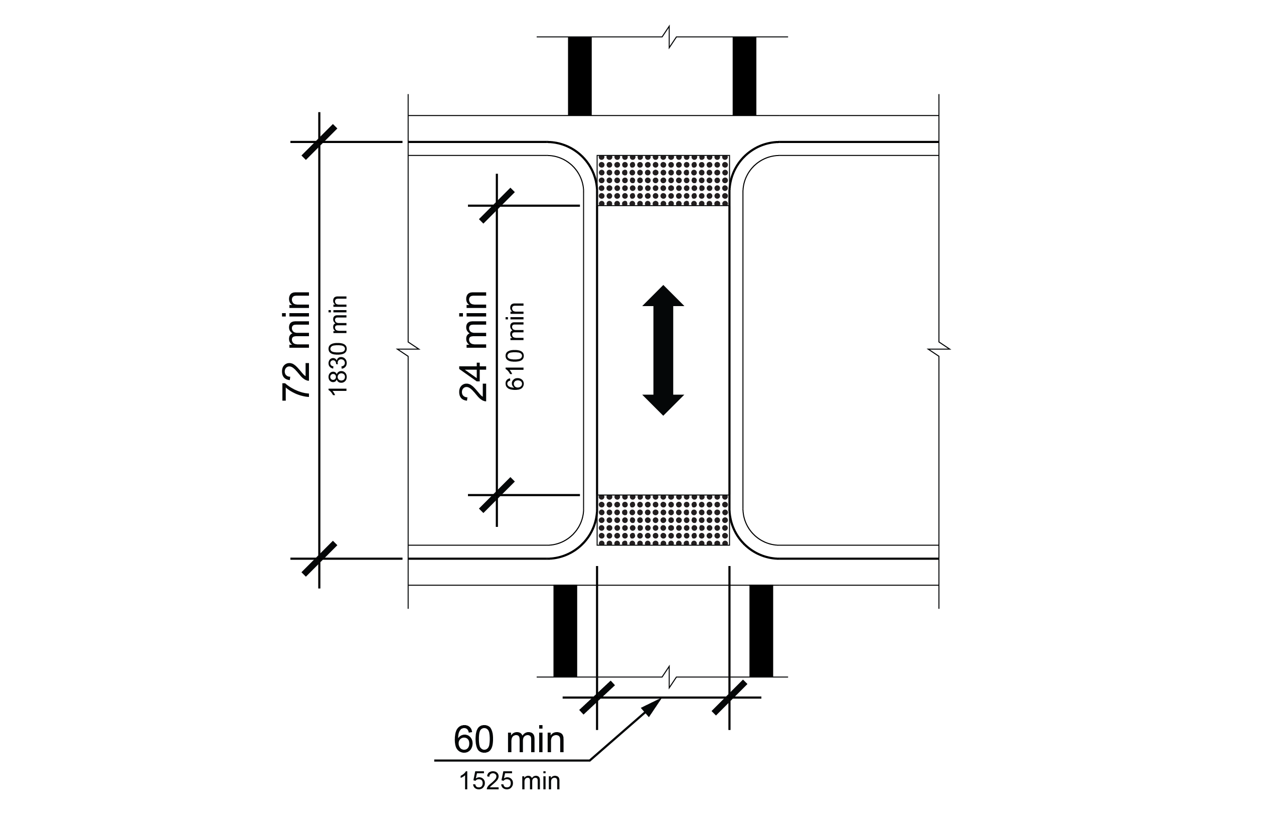
R310.3.1 Access Aisles
Perpendicular on-street parking spaces shall have adjacent access aisles 96 inches (2440 mm) wide minimum extending the full length of the parking space. One access aisle shall be permitted to serve two parking spaces where front and rear entry parking are both permitted. Where an access aisle serves only one parking space and parking is restricted to either front entry or rear entry orientation, the access aisle shall be located on the passenger side of the vehicle.
R310.4 Angled Parking Spaces
Accessible angled parking spaces shall comply with R310.4.
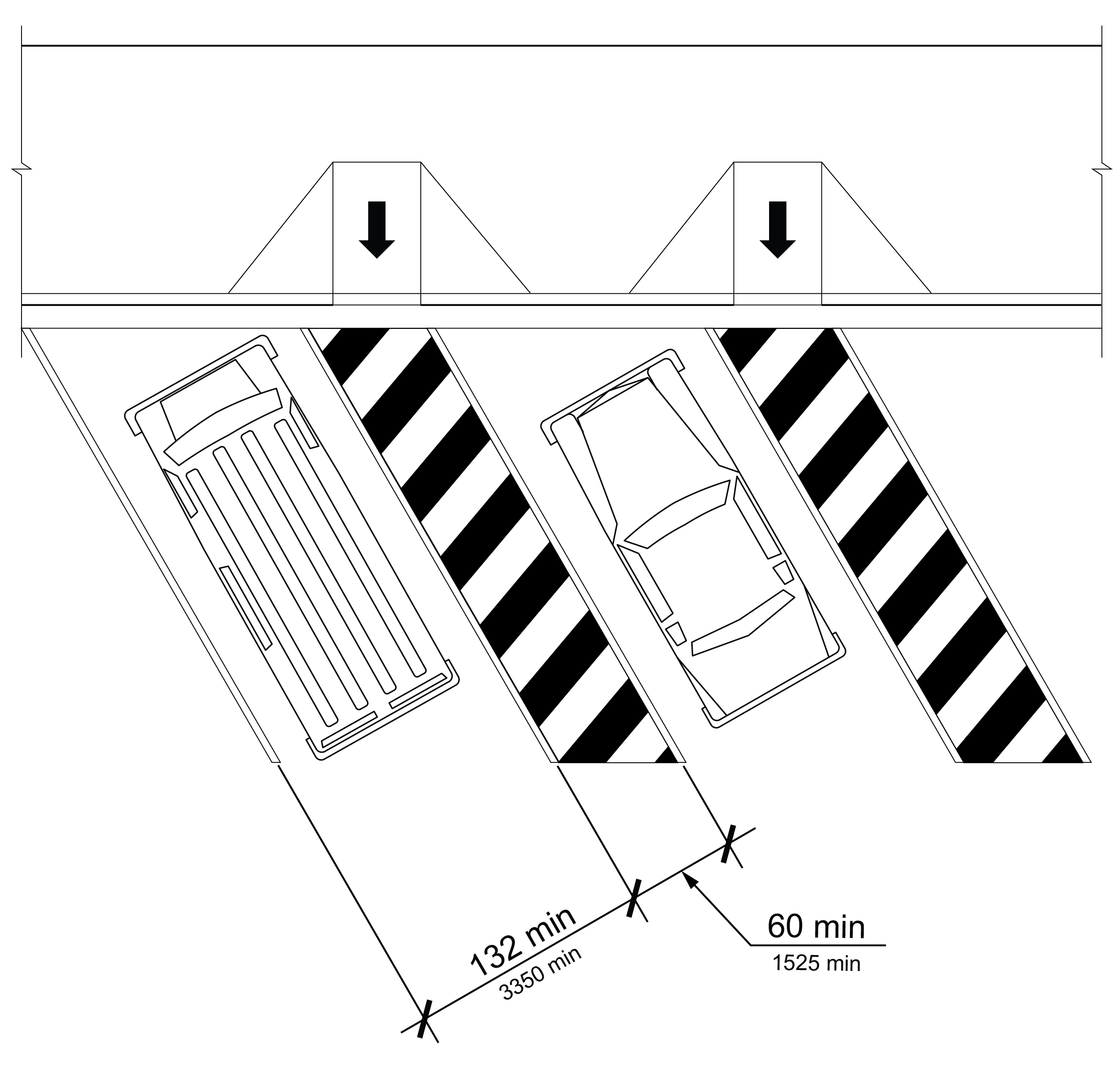
R310.4.1 Width
The width of an angled parking space shall be 132 inches (3350 mm).
R310.4.2 Access Aisles
Each angled on-street parking space shall have an adjacent access aisle 60 inches (1525 mm) wide minimum extending the full length of the parking space on the passenger side.
R310.5 Common Requirements for Perpendicular and Angled Parking Spaces
Perpendicular and angled parking spaces shall comply with R310.5
R310.5.1 Access Aisle Markings
The access aisle surface shall be marked to discourage parking in the access aisle.
R310.5.2 Access Aisle Location
Access aisles shall be located at the same level as the parking space they serve and shall not encroach on the traveled way.
R310.5.3 Pedestrian Access Route Connection
Access aisles shall connect to pedestrian access routes. Where curb ramps and blended transitions are used, they shall not reduce the required width or length of access aisles and parking spaces. Curb ramps and blended transitions shall be provided in accordance with R203.6.1.4 and shall comply with R304. A detectable warning surface is not required on a curb ramp or blended transition used exclusively to connect on-street parking access aisles to pedestrian access routes.
EXCEPTION: In alterations, the access aisle may connect to an existing pedestrian circulation path in accordance with R202.2.
R310.5.4 Surfaces
Surfaces of parking spaces and access aisles serving them shall comply with R302.6, except that changes in level are not permitted.
R310.5.5 Identification
Perpendicular or angled on-street parking spaces shall be identified by signs displaying the International Symbol of Accessibility complying with R411. The signs shall be located at the head of the parking space. Signs shall be 60 inches (1525 mm) minimum above the ground surface measured to the bottom of the sign.
R310.6 Parking Meters and Parking Pay Stations
Parking meters and parking pay stations that serve accessible parking spaces shall provide operable parts complying with R403. The clear space required by R403.2 shall be located so that displays and information on parking meters and pay stations are visible from a point located 40 inches (1015 mm) maximum above the center of the clear space in front of the parking meter or parking pay station.
R311 Passenger Loading Zones
R311.1 General
Accessible passenger loading zones shall comply with R311.
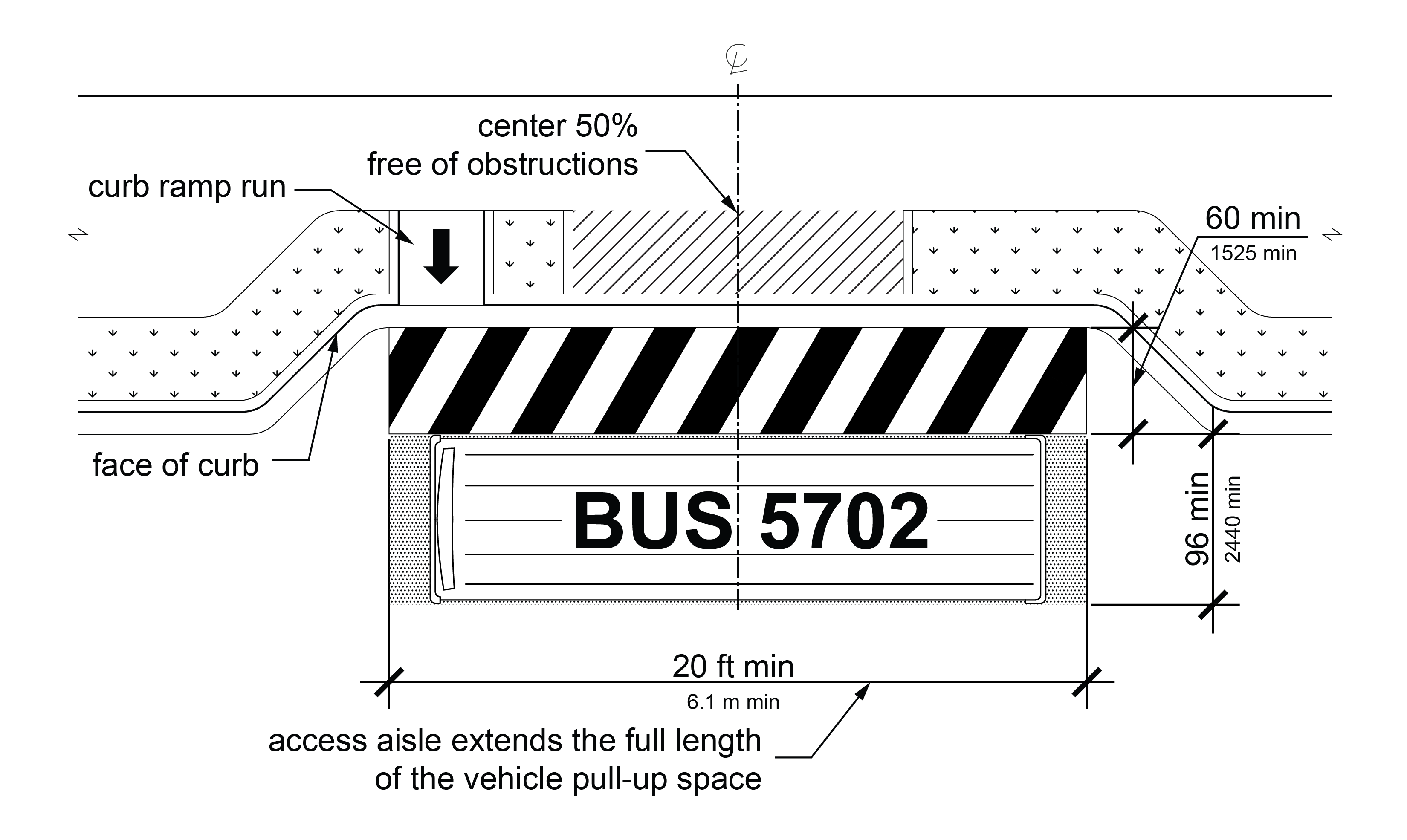
R311.2 Vehicle Pull-Up Space
Accessible passenger loading zones shall provide a vehicular pull-up space that is 96 inches (2440 mm) wide minimum and 20 feet (6.1 m) long minimum.
R311.3 Access Aisle
Vehicle pull-up spaces shall have adjacent access aisles complying with R311.3 that are 60 inches (1525 mm) wide minimum extending the full length of the vehicle pull-up space. Access aisles shall be at the same level as the vehicle pull-up space they serve and shall not encroach on the traveled way.
R311.3.1 Clearance Adjacent to Passenger Loading Zone
The center 50 percent of the length of the sidewalk, or other surface, adjacent to an accessible passenger loading zone shall be free of obstructions and comply with R302.6.
R311.3.2 Marking
Access aisle surfaces shall be marked to discourage parking in them.
R311.4 Surfaces
Surfaces of vehicle pull-up spaces and the access aisles serving them shall comply with R302.6, except that changes in level are not permitted.
R311.5 Pedestrian Access Route Connection
Access aisles shall connect to pedestrian access routes. Where curb ramps and blended transitions are used, they shall be provided in accordance with R203.6.1.4 and comply with R304, and shall not reduce the required width or length of access aisles. Detectable warning surfaces are not required on curb ramps and blended transitions used exclusively to connect access aisles to pedestrian access routes.
EXCEPTION: In alterations, the access aisle may connect to an existing pedestrian circulation path in accordance with R202.2.
