Appendix to Part 1190
Authority: 29 U.S.C. 792; 42 U.S.C. 12204; 42 U.S.C. 4151 et seq.
§ 1190.1 Accessibility Guidelines
The accessibility guidelines for pedestrian facilities in the public right-of-way are set forth in the appendix to this part. When the guidelines are adopted, with or without additions and modifications, as accessibility standards in regulations issued by other federal agencies implementing the Americans with Disabilities Act, Section 504 of the Rehabilitation Act, and the Architectural Barriers Act, compliance with the accessibility standards is mandatory.
Appendix to Part 1190
Accessibility Guidelines for Pedestrian Facilities in the Public Right-of-Way
Chapter 1: Application and Administration
R101 Purpose and Application
R101.1 Purpose
These guidelines contain scoping and technical requirements to ensure that pedestrian facilities located in the public right-of-way (including a public right-of-way that forms the boundary of a site or that lies within a site bounded by a property line), are readily accessible to and usable by pedestrians with disabilities.
R101.2 Application to ADA-Covered Facilities
These guidelines apply to pedestrian facilities in public rights-of-way to the extent required by regulations issued by Federal agencies under the Americans with Disabilities Act of 1990, as amended (42 U.S.C. 12101 et seq.) (ADA).
R101.3 Application to ABA-Covered Facilities
These guidelines apply to pedestrian facilities in public rights-of-way to the extent required by regulations issued by Federal agencies under the Architectural Barriers Act of 1968 (42 U.S.C. 4151 et seq.) (ABA).
R101.4 Effect on Existing Pedestrian Facilities
These guidelines do not address existing pedestrian facilities unless the pedestrian facilities are altered at the discretion of a covered entity. The Department of Justice has authority over existing facilities that are subject to the requirement for program access under title II of the ADA. Any determination that this document applies to existing facilities subject to the program access requirement is solely within the discretion of the Department of Justice and is effective only to the extent required by regulations issued by the Department of Justice.
R102 Deviations from These Guidelines
R102.1 ADA-Covered Facilities and Equivalent Facilitation
The use of alternative designs, products, or technologies that result in substantially equivalent or greater accessibility and usability than the requirements in these guidelines shall be permitted for pedestrian facilities in the public right-of-way subject to the ADA.
R102.2 ABA-Covered Facilities and Waivers or Modifications
Equivalent facilitation is not permitted for pedestrian facilities in the public right-of-way subject to the ABA. The ABA authorizes the Administrator of the General Services Administration, the Secretary of the Department of Housing and Urban Development, the Secretary of the Department of Defense, and the United States Postal Service to modify or waive the accessibility standards for buildings and facilities covered by the ABA on a case-by-case basis, upon application made by the head of the department, agency, or instrumentality of the United States concerned and upon a determination that the waiver is clearly necessary. Pursuant to Section 502(b)(1) of the Rehabilitation Act of 1973, 29 U.S.C. § 792(b), the Access Board shall ensure that modifications and waivers are based on findings of fact and are not inconsistent with the ABA.
R103 Conventions
Advisory: Figures are provided for informational purposes only.
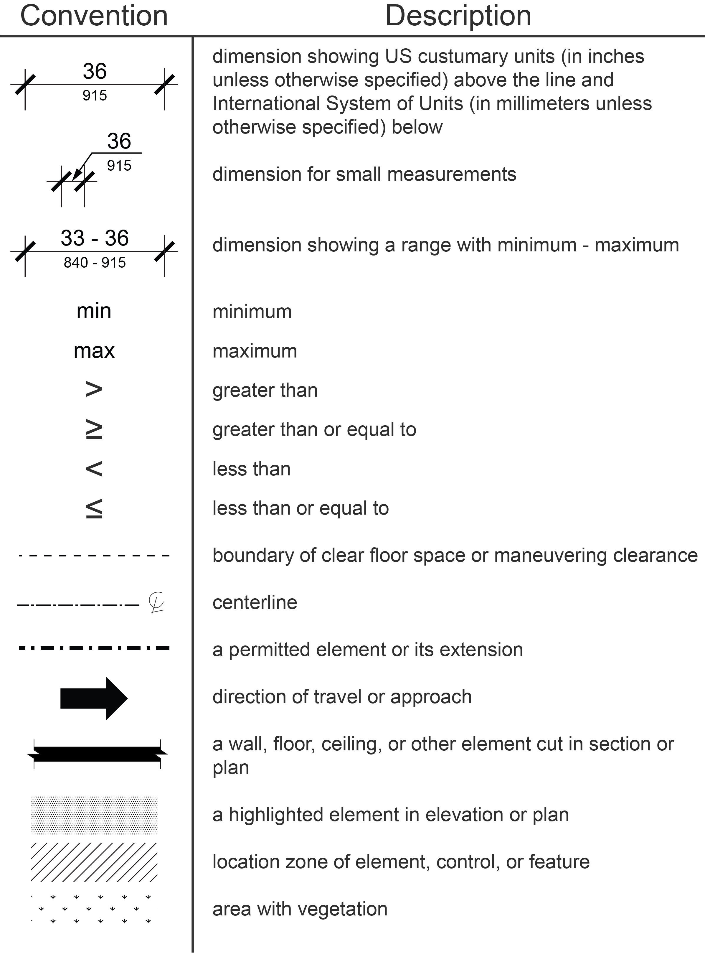
R103.1 Conventional Industry Tolerances
All dimensions are subject to conventional industry tolerances except where requirements are stated as a range with specific minimum or maximum endpoints.
R103.2 Calculation of Percentages
Where the required number of elements or facilities to be provided is determined by calculations of ratios or percentages and remainders or fractions result, the next greater whole number of such elements or facilities shall be provided.
R103.3 Units of Measurement
Measurements are stated in U.S. customary units and metric units. The values stated in each system (U.S. customary units and metric units) may not be exact equivalents, and each system shall be used independently of the other. Slopes are expressed in terms of both ratios and percentages. Ratios and percentages may not be exact equivalents, and each shall be used independently of the other.
R104 Definitions
R104.1 Undefined Terms
Terms that are not defined in R104.3 or in regulations issued by the Department of Justice and the Department of Transportation under the ADA, the four standard setting agencies under the ABA or other federal agencies that adopt these guidelines as accessibility standards shall be given their ordinarily accepted meaning in the sense that the context implies.
R104.2 Interchangeability
Words, terms, and phrases used in the singular include the plural and those used in the plural include the singular.
R104.3 Defined Terms
For the purpose of these guidelines, the following terms have the indicated meaning:
A
- Accessible
- A pedestrian facility or element in the public right-of-way that complies with these guidelines.
- Accessible Pedestrian Signal
- A device that communicates information about pedestrian signal timing in non-visual formats such as audible tones or speech messages, and vibrating surfaces.
- Alteration or altered
- A change to or an addition of a pedestrian facility in an existing, developed public right-of-way that affects or could affect pedestrian access, circulation, or usability.
B
- Blended Transition
- A wraparound connection at a corner, or a flush connection where there is no curb to cut through, other than a curb ramp.
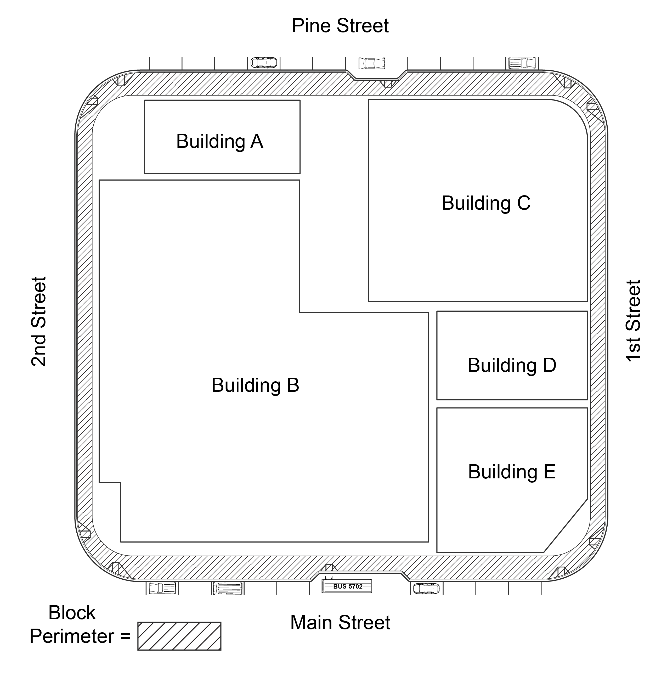
- Block Perimeter
- The near side of the streets surrounding a block. For example, on a square block bounded by Main Street to the south, Pine Street to the north, 1st Street to the east, and 2nd Street to the west, the block perimeter includes the north side of Main Street, the south side of Pine Street, the west side of 1st Street, and the east side of 2nd Street.
- Boarding Platform
- A platform raised above standard curb height used for transit vehicle boarding and alighting.
- Building:
- Any structure used or intended for supporting or sheltering any use or occupancy.
C
- Crosswalk
- That part of a roadway that is located at an intersection included within the connections of the lateral lines of the pedestrian circulation paths on opposite sides of the highway measured from the curbs, or in the absence of curbs, from the edges of the traversable roadway, and in the absence of a pedestrian circulation path on one side of the roadway, the part of a roadway included within the extension of the lateral lines of the pedestrian circulation path at right angles to the center line;
- or at any portion of a roadway at an intersection or elsewhere distinctly indicated as a pedestrian crossing by pavement marking lines on the surface.
- Crosswalks at intersections may be marked or unmarked.
- Cross Slope
- The slope that is perpendicular to the direction of pedestrian travel.
- Curb
- A raised feature along the side of a street that delineates the edge of the roadway or pedestrian circulation path.
- Curb Line
- A line at the face of the curb that marks the transition between the curb and the gutter or street.
- Curb Ramp
- A sloped connection that is cut through or built up to a curb. Curb ramps may be perpendicular or parallel to the curb or to the street they serve or be a combination thereof.
D
- Detectable Warning Surface
- A standardized surface feature built in or applied to pedestrian circulation paths and other pedestrian facilities to warn of hazards.
- Developed
- Containing buildings, pedestrian facilities, roadways, utilities, or elements.
E
- Element
- An architectural or mechanical component of a building, pedestrian facility, space, site, or public right-of-way.
G
- Grade
- See Running slope.
- Grade Break
- The line where two surface planes with different running slopes meet.
H
- Highway
- A general term denoting a public way for purposes of vehicular travel, including the entire area within the public right-of-way.
M
- Median
- The area between two roadways of a divided highway measured from edge of traveled way to edge of traveled way. The median excludes turn lanes. The median width might be different between intersections, interchanges, and at opposite approaches of the same intersection.
O
- Operable Part
- A component of an element used to insert or withdraw objects, or to activate, deactivate, or adjust the element, or to interact with the element.
P
- Parallel Curb Ramp
- A curb ramp with a running slope that is parallel to the curb or street it serves.
- Passenger Loading Zone
- An area that is specifically designed or designated for loading and unloading passengers, but that does not primarily serve vehicles on a fixed or scheduled route.
- Pedestrian
- A person on foot, travelling by wheelchair or other mobility device, on skates, or on a skateboard.
- Pedestrian Access Route
- An accessible, continuous, and unobstructed path of travel for use by pedestrians with disabilities within a pedestrian circulation path.
- Pedestrian Activated Warning Devices
- Devices that are installed in conjunction with a warning sign and are activated to alert vehicle operators to the presence of a pedestrian, such as rectangular rapid flashing beacons.
- Pedestrian Change Interval
- An interval during which the flashing upraised hand (symbolizing “don’t walk”) signal indication is displayed.
- Pedestrian Circulation Path
- A prepared exterior or interior surface provided for pedestrian use in the public right-of-way.
- Pedestrian Facility
- A structure, route, or space for pedestrian circulation or use located in the public right-of-way.
- Pedestrian Hybrid Beacon
- A special type of hybrid beacon used to warn and control traffic at an unsignalized location to assist pedestrians in crossing a street at a marked crosswalk.
- Pedestrian Refuge Island
- A defined area 72 inches (1828 mm) long minimum in the direction of pedestrian travel located between traffic lanes for pedestrian refuge within a median, splitter island, or channelizing island.
- Pedestrian Signal Head
- A device containing the walking person symbol (symbolizing “walk”) and the upraised hand symbol (symbolizing “don’t walk”), that is installed to direct pedestrian traffic at a crosswalk.
- Perpendicular Curb Ramp
- A curb ramp with a running slope that is perpendicular to the curb or the street it serves.
- Public Right-of-Way
- Public land acquired for or dedicated to transportation purposes, or other land where there is a legally established right for use by the public for transportation purposes.
- Push Button
- A button to activate a device or signal timing for pedestrians, bicyclists, or others crossing a roadway.
- Push Button Locator Tone
- A repeating sound that informs approaching pedestrians that a push button exists to actuate pedestrian timing or receive additional information and that enables pedestrians who are blind or have low vision to locate the push button.
Q
- Qualified Historic Building or Facility
- A building or facility that is listed in or eligible for listing in the National Register of Historic Places or designated as historic under an appropriate state or local law.
R
- Ramp
- A sloped walking surface with a running slope steeper than 1:20 (5.0%) that accomplishes a change in level and is not part of a pedestrian circulation path that follows the roadway grade. A curb ramp is not a ramp.
- Roadway
- That portion of a highway improved, designed, or ordinarily used for vehicular travel and parking lanes, but exclusive of the sidewalk, berm, or shoulder.
- Roundabout
- A circular intersection with yield control at entry, which permits a vehicle on a circular roadway to proceed, and with deflection of the approaching vehicle counterclockwise around a central island.
- Running Slope
- The slope that is parallel to the direction of pedestrian travel.
S
- Shared Use Path
- A multi-use path designed primarily for use by bicyclists, pedestrians, and other authorized motorized and non-motorized users, for transportation purposes, and that may also be used for recreation. Shared use paths are physically separated from motor vehicle traffic by an open space or barrier and are either within the highway or other public right-of-way.
- Sidewalk
- That portion of a highway between the curb line, or the lateral line of a roadway, and the adjacent property line, or on easements of private property, that is paved or improved and intended for use by pedestrians.
- Splitter Island
- A median island used to separate opposing directions of traffic entering and exiting a roundabout.
- Stair
- A change in elevation comprised of at least one tread and riser. A curb is not a stair.
- Standard Curb Height
- The typical height of a curb according to local standards for a given road type, but usually between 3 inches (75 mm) and 9 inches (230 mm) high relative to the surface of the roadway or gutter.
- Street
- See Roadway.
T
- Transit Shelter
- A structure provided at a transit stop to provide passengers protection from the weather.
- Transit Stop
- An area that is designated for passengers to board or alight from buses, rail cars, and other transportation vehicles that operate on a fixed route or scheduled route, including bus stops and boarding platforms.
- This definition does not include intercity rail except where a stop is located in the public right-of-way.
- Transitional Segment
- The portion of a pedestrian circulation path that connects adjacent surfaces with different slopes or dimensions to provide a smooth transition.
- Traveled Way
- The portion of the roadway for the movement of vehicles, exclusive of the shoulder, berm, sidewalk, and parking lane.
V
- Vibrotactile
- A method of communicating information by touch using a vibrating surface.
W
- Walk Interval
- An interval during which the walking person (symbolizing “walk”) signal indication is displayed.
Chapter 2: Scoping Requirements
R201 General
R201.1 Scope
All newly constructed pedestrian facilities and altered portions of existing pedestrian facilities for pedestrian circulation and use located in the public right-of-way shall comply with these guidelines.
EXCEPTION: Pedestrian facilities within vaults, tunnels, and other spaces used only by service personnel for maintenance, repair, or monitoring of equipment are not required to comply with these guidelines.
R201.2 Temporary and Permanent Pedestrian Facilities
The requirements in these guidelines shall apply to temporary and permanent pedestrian facilities and elements in the public right-of-way. Where a pedestrian circulation path or transit stop is temporarily closed by construction, maintenance operations, or similar conditions, an alternate pedestrian access route or transit stop shall be provided in accordance withR204.
R201.3 Buildings, Structures, and Elements
Buildings, structures, and elements in the public right-of-way that are not covered by the requirements in these guidelines shall comply with the applicable requirements in 36 CFR part 1191 (ADA & ABA Accessibility Guidelines). Examples include, but are not limited to, buildings, structures, and elements at safety rest areas or park and ride lots, temporary performance stages and reviewing stands.
R202 Alterations
R202.1 General
Alterations to pedestrian facilities shall comply with R202.
R202.2 Connection to Pedestrian Circulation Path
Where pedestrian facilities are altered, they shall be connected by a pedestrian access route complying with R302 to an existing pedestrian circulation path. A transitional segment may be used in the connection.
R202.3 Existing Physical Constraints
In alterations, where existing physical constraints make compliance with applicable requirements technically infeasible, compliance with these requirements is required to the maximum extent feasible. Existing physical constraints include, but are not limited to, underlying terrain, underground structures, adjacent developed facilities, drainage, or the presence of a significant natural or historic feature.
R202.4 Reduction in Access Prohibited
An alteration to pedestrian facilities or elements shall not decrease the accessibility of an existing pedestrian facility or element or an accessible connection to an adjacent building or site below the requirements in these guidelines.
R202.5 Alterations to Qualified Historic Facilities
Where the State Historic Preservation Officer or Advisory Council on Historic Preservation determines that compliance with an applicable requirement of these guidelines would threaten or destroy the historic significance of a qualified historic building or facility, compliance with that requirement is required to the maximum extent feasible without threatening or destroying the historic significance of the qualified historic building or facility.
R203 Pedestrian Access Routes
R203.1 General
Where provided, the pedestrian facilities addressed in R203 shall contain or connect a pedestrian access route, and shall comply with these guidelines.
R203.2 Connection to Accessible Facilities
Pedestrian access routes shall connect accessible elements, spaces, and pedestrian facilities in accordance with R203.2.
R203.2.1 Connection to Accessible Facilities subject to the ADA
Pedestrian access routes subject to the ADA shall connect accessible elements, spaces, and pedestrian facilities required to be accessible and connect to accessible routes required by section 206.2.1 of appendix B to 36 CFR part 1191 (ADA & ABA Accessibility Guidelines) that connect building and facility entrances to public streets and sidewalks.
EXCEPTION: Where elements are altered, on or adjacent to an existing pedestrian circulation path, the existing pedestrian circulation path need not be altered to provide a pedestrian access route complying with R202.2.
R203.2.2 Connection to Accessible Facilities subject to the ABA
Pedestrian access routes subject to the ABA shall connect accessible elements, spaces, and pedestrian facilities required to be accessible and connect to accessible routes required by section F206.2.1 of appendix C to 36 CFR part 1191 (ADA & ABA Accessibility Guidelines) that connect building and facility entrances to public streets and sidewalks.
EXCEPTION: Where elements are altered, on or adjacent to an existing pedestrian circulation path, the existing pedestrian circulation path need not be altered to provide a pedestrian access route complying with R202.2.
R203.3 Pedestrian Circulation Paths
Pedestrian access routes complying with R302 shall be provided within pedestrian circulation paths, including sidewalks and shared use paths. Transitional segments may be used to connect new or altered pedestrian access routes to existing pedestrian circulation paths, and the differences between adjacent surface characteristics shall be minimized to provide a smooth transition.
R203.4 Crosswalks
A pedestrian access route complying with R302 shall be provided within and for the full length of a crosswalk, including medians and pedestrian refuge islands. Crosswalks shall comply with R306.
R203.5 Pedestrian At-Grade Rail Crossing
Where a pedestrian circulation path crosses at-grade rail tracks, a pedestrian access route complying with R302 shall be included within the pedestrian at-grade rail crossing. Pedestrian at-grade rail crossings shall comply with R306.
R203.6 Curb Ramps and Blended Transitions
A curb ramp, blended transition, or a combination of curb ramps and blended transitions shall be provided in accordance with R203.6 and shall comply with R304.
R203.6.1 Placement
Placement of curb ramps and blended transitions shall comply with R203.6.1.
R203.6.1.1 Crosswalks at an Intersection
At an intersection corner, one curb ramp or blended transition shall be provided for each crosswalk, or a single blended transition that spans all crosswalks at the intersection corner may be provided. Where pedestrian crossing is prohibited, curb ramps or blended transitions shall not be provided, and the pedestrian circulation path shall be either (a) separated from the roadway with landscaping or other non-prepared surface or (b) separated from the roadway by a detectable vertical edge treatment with a bottom edge 15 inches maximum above the pedestrian circulation path.
EXCEPTION: In alterations, where existing physical constraints make compliance with R203.6.1.1 technically infeasible, a single curb ramp complying with R304 shall be permitted at the apex of the intersection corner.
R203.6.1.2 Mid-Block and Roundabout Crosswalks
At a mid-block or roundabout crosswalk, curb ramps or blended transitions shall be provided on both ends of the crosswalk. Where pedestrian crossing is not intended, curb ramps or blended transitions shall not be provided, and the pedestrian circulation path shall be either (a) separated from the roadway with landscaping or other non-prepared surface or (b) separated from the roadway by a detectable vertical edge treatment with a bottom edge 15 inches maximum above the pedestrian circulation path.
R203.6.1.3 Parallel On-Street Parking
At parallel on-street parking spaces complying with the dimensions specified in R310.2.1, a curb ramp or blended transition shall be provided at either end of the parking space if needed to connect the parking space to a pedestrian access route.
R203.6.1.4 Perpendicular and Angled On-Street Parking and Passenger Loading Zones
At perpendicular and angled on-street parking spaces, and at passenger loading zones, a curb ramp or blended transition shall be provided if needed to connect the access aisle to a pedestrian access route.
R203.6.2 Alterations to Crosswalks
When alterations are made to crosswalks, curb ramps or blended transitions shall be provided on both ends of the crosswalk where the pedestrian access route crosses a curb.
R203.7 Pedestrian Overpasses and Underpasses
Pedestrian overpasses and underpasses shall contain a pedestrian access route complying with R302. Where an overpass, underpass, bridge, or similar structure is designed for pedestrian use only, or pedestrian and bicycle use only, and the approach slope to the structure exceeds 1:20 (5.0%), a ramp complying with R407, or an elevator or limited use/limited application elevator complying with sections 407 or 408 of Appendix D to 36 CFR part 1191 (ADA & ABA Accessibility Guidelines), shall be provided. Elevators and limited use/limited application elevators shall be unlocked and independently usable during the operating hours of the pedestrian facility served.
EXCEPTION: In alterations, where existing physical constraints make compliance with R203.7 technically infeasible, a platform lift complying with section 410 of Appendix D to 36 CFR part 1191 (ADA & ABA Accessibility Guidelines) shall be permitted.
R203.8 Ramps
Where provided, ramps shall comply with R407.
R203.9. Elevators and Limited Use/Limited Application Elevators
Where provided, elevators and limited use/limited application elevators shall comply with sections 407 or 408 of Appendix D to 36 CFR part 1191 (ADA & ABA Accessibility Guidelines).
R203.10 Platform Lifts
In alterations, where the use of elevators or limited use elevators is not technically feasible, platform lifts may be used and shall comply with section 410 of Appendix D to 36 CFR part 1191 (ADA & ABA Accessibility Guidelines).
R203.11 Doors, Doorways, and Gates
Doors, doorways, and gates that are part of a pedestrian access route shall comply with section 404 of Appendix D to 36 CFR part 1191 (ADA & ABA Accessibility Guidelines).
R204 Alternate Pedestrian Access Routes, Transit Stops, and Passenger Loading Zones
R204.1 Alternate Pedestrian Access Route
When a pedestrian circulation path is temporarily not accessible due to construction, maintenance operations, closure, or other similar conditions, an alternate pedestrian access route must be provided and comply with R303 and R402.
EXCEPTION: If establishing or maintaining an alternate pedestrian access route is technically infeasible due to site conditions or existing physical constraints, an alternate means of providing access for pedestrians with disabilities shall be permitted.
R204.2 Alternate Transit Stops
Where accessible transit stops are temporarily not accessible due to construction, maintenance operations, or other similar conditions, alternate transit stops complying with R309 shall be provided.
R204.3 Alternate Passenger Loading Zones
Where a permanently designated passenger loading zone is temporarily not accessible due to construction, maintenance operations, or other similar conditions, and a temporary passenger loading zone is provided, it must comply with R311.
R205 Detectable Warning Surfaces
R205.1 General
Detectable warning surfaces shall be provided in accordance with R205.
R205.2 Curb Ramps and Blended Transitions
Curb ramps shall have detectable warning surfaces complying with R205.2.1. Blended transitions shall have detectable warning surfaces complying with R205.2.2.
EXCEPTION: Detectable warning surfaces are not required on curb ramps and blended transitions used exclusively to connect passenger loading zones, accessible parallel on-street parking spaces, and access aisles for perpendicular and angled parking spaces to pedestrian access routes.
R205.2.1 Curb Ramps
Curb ramps located at crosswalks shall have detectable warning surfaces complying with R305.1 and either R305.2.1 or R305.2.2.
R205.2.2 Blended Transitions
Blended transitions located at crosswalks shall have detectable warning surfaces complying with R305.1 and R305.2.3.
R205.3 Pedestrian Refuge Islands
Cut-through pedestrian refuge islands shall have detectable warning surfaces complying with R305.1 and R305.2.4.
R205.4 Pedestrian At-Grade Rail Crossings
Pedestrian at-grade rail crossings not located within a street shall have detectable warning surfaces complying with R305.1 and R305.2.5. Pedestrian at-grade rail crossings located within a street at a crosswalk shall not have detectable warning surfaces adjacent to the railway.
R205.5 Boarding Platforms
Boarding platforms at transit stops that are not protected by screens or guards along the sides of the boarding and alighting areas facing the transit vehicles shall have detectable warning surfaces complying with R305.1 and R305.2.6.
R205.6 Sidewalk and Street-Level Rail Boarding and Alighting Areas
Boarding and alighting areas at sidewalk or street-level transit stops for rail vehicles that are not protected by screens or guards along the side of the boarding and alighting areas facing the rail vehicles shall have detectable warning surfaces complying with R305.1 and R305.2.7.
R205.7 Driveways
Pedestrian circulation paths at driveways controlled with yield or stop control devices or traffic signals shall have detectable warning surfaces complying with R305.2.8.
R206 Pedestrian Signal Heads and Pedestrian Activated Warning Devices
R206.1 General
Where provided, pedestrian signal heads and pedestrian activated warning devices shall comply with R206. The accessible features required by these guidelines shall be available at all times.
R206.2 Traffic Control Signals and Hybrid Beacons with Pedestrian Signal Heads
Where pedestrian signal heads are provided at crosswalks, the walk indication shall comply with R308. Pedestrian signal heads must have a pedestrian push button complying with R307, except for R307.7, or passive detection or pretimed operation that activates audible and vibrotactile indications complying with R308.
R206.3 Pedestrian Activated Warning Devices
Pedestrian activated warning devices shall have pedestrian push buttons complying with R307, except for R307.2 and R307.6, or passive detection that operates audible indications complying with R307.7.
R207 Protruding Objects and Vertical Clearance
R207.1 General
Protruding objects and vertical clearance along any portion of a pedestrian circulation path shall comply with R402.
R208 Pedestrian Signs
R208.1 General
Where provided, signs intended solely for pedestrians, including transit signs, and all signs serving shared use paths, shall comply with R410.
EXCEPTIONS: 1. Transit schedules, timetables, and maps are not required to comply with R410.
2. Signs mounted immediately above or incorporated into a push button detector unit are not required to comply with R410.
R209 Street Furniture
R209.1 General
Where provided, street furniture shall comply with the applicable requirements in R209.
R209.2 Drinking Fountains
Drinking fountains shall comply with sections 602.1 through 602.6 of Appendix D to 36 CFR part 1191 (ADA & ABA Accessibility Guidelines).
R209.3 Public Street Toilets
Public street toilets shall be provided in accordance with R209.3.
R209.3.1 Permanent Public Street Toilets
Permanent public street toilets shall comply with sections 603 through 610 of Appendix D to 36 CFR part 1191 (ADA & ABA Accessibility Guidelines).
R209.3.2 Portable Toilet Units
Portable toilet units shall comply with section 603 of Appendix D to 36 CFR part 1191 (ADA & ABA Accessibility Guidelines). Where multiple single user portable toilet units are clustered at a single location, at least 5 percent, but no fewer than one of each type of the toilet units at each cluster shall be required to comply with 603 Appendix D to 36 CFR part 1191 (ADA & ABA Accessibility Guidelines). Portable toilet units complying with section 603 shall be identified by the International Symbol of Accessibility complying with R411.
R209.4 Tables
At least 5 percent of tables at each group of adjacent tables, but no fewer than one, shall comply with section 902 of Appendix D to 36 CFR part 1191 (ADA & ABA Accessibility Guidelines).
R209.5 Sales or Service Counters
Sales or service counters shall comply with section 904.4 of Appendix D to 36 CFR part 1191 (ADA & ABA Accessibility Guidelines).
EXCEPTION 1: Sales or service counters that are located in a building subject to the ADA that is not itself in the public right-of-way but that directly serve the public right-of-way, such as at a service window accessed from the sidewalk, may comply with section 227.3 of Appendix B to 36 CFR part 1191 (ADA & ABA Accessibility Guidelines).
EXCEPTION 2: Sales or service counters that are located in a building subject to the ABA that is not itself in the public right-of-way but that directly serve the public right-of-way, such as at a service window accessed from the sidewalk, may comply with section F227.3 of Appendix C to 36 CFR part 1191 (ADA & ABA Accessibility Guidelines).
R209.6 Benches
Benches, other than those that are part of tables complying with R209.4, shall comply with R209.6.
R209.6.1 Benches at Transit Stops and Shelters
Benches provided at transit stops shall have clear space complying with R404 next to either end of the bench, or if the bench has no end, such as a circular bench, the clear space shall either be integral to the bench or no more than 18 inches (455 mm) from the front of the bench. Benches provided within transit shelters shall have clear space complying with R309.2.2.
R209.6.2 Benches Not at Transit Stops and Shelters
At least 50 percent, but no less than one, of benches at each group of adjacent benches shall provide clear space complying with R404. The clear space shall be located next to either end of the bench, or if the bench has no end, such as a circular bench, the clear space shall either be integral to the bench or no more than 18 inches (455 mm) from the front of the bench.
R209.7 Operable Parts of Other Fixed Elements
Operable parts of other fixed elements to be used by pedestrians shall comply with R403.
R210 Transit Stops and Transit Shelters
R210.1 General
Where provided, transit stops and transit shelters shall comply with R309.
R210.2 Fare Vending Machines
Where provided at transit stops and transit shelters, fare vending machines shall comply with R403 and section 707 of Appendix D to 36 CFR part 1191 (ADA & ABA Accessibility Guidelines), except for 707.2 and 707.3.
R210.3. Operable Parts of Other Fixed Elements
Operable parts of other fixed elements at transit stops and shelters intended to be used by pedestrians shall comply with R403.
R211 On-Street Parking Spaces
R211.1 General
Where on-street parking is provided and is metered or designated by signs or pavement markings, accessible parking spaces complying with R310 shall be provided in accordance with R211 and Table R211.
EXCEPTIONS: 1. On-street parking spaces designated exclusively as residential parking shall not be required to comply with R211 and shall not be counted for purposes of Table R211.
2. On-street parking spaces designated exclusively for commercial or law enforcement vehicles shall not be required to comply with R211 and shall not be counted for purposes of Table R211.
3. Where on-street parking spaces are altered, the requirements of R211 shall apply only to the affected parking spaces until the minimum number of accessible on-street parking spaces as specified in Table R211 are provided.
R211.2 Parking on Block Perimeter
Where parking spaces are provided on a block perimeter and are metered or designated by signs or pavement markings, accessible parking spaces complying with R310 shall be provided in accordance with Table R211. Where parking is metered or designated by signs or pavement markings, but individual spaces are not marked, each 20 feet (6.1 m) of block perimeter where parking is designated shall be counted as one parking space.
Advisory: Figures are provided for informational purposes only.
R211.3 Parking not on Block Perimeter
Where parking spaces are provided on a section of a street that is not part of a block perimeter, accessible parking spaces complying with R310 shall be provided in accordance with Table R211. Where parking is metered or designated by signs or pavement markings, but individual spaces are not marked, each 20 feet (6.1 m) of street where parking is designated shall be counted as one parking space.
Table R211 On-Street Parking Spaces
Table R211 On-Street Parking Spaces
| Total Number of Metered or Designated Parking Spaces | Minimum Required Number of Accessible Parking Spaces |
|---|---|
| 1 to 25 | 1 |
| 26 to 50 | 2 |
| 51 to 75 | 3 |
| 76 to 100 | 4 |
| 101 to 150 | 5 |
| 151 to 200 | 6 |
| 201 and over | 4 percent of total |
R212 Passenger Loading Zones
R212.1 General
Where permanently designated passenger loading zones other than transit stops are provided, at least one accessible passenger loading zone complying with R311 shall be provided in every continuous 100 feet (30 m) of loading zone space, or fraction thereof.
R213 Stairs and Escalators
R213.1 General
Where provided on pedestrian circulation paths, stairs shall comply with R408 and escalators shall comply with section 810.9 of Appendix D to 36 CFR part 1191 (ADA & ABA Accessibility Guidelines). Stairs and escalators shall not be part of pedestrian access routes.
R214 Handrails
R214.1 General
Where provided on pedestrian circulation paths, handrails shall comply with R409.
Chapter 3: Technical Requirements
Advisory: Figures are provided for informational purposes only.
R301 General
R301.1 Scope
The technical requirements in Chapter 3 shall apply where required by Chapter 2 or where referenced by a requirement in these guidelines.
R302 Pedestrian Access Routes
R302.1 General
Pedestrian access routes shall comply with R302.
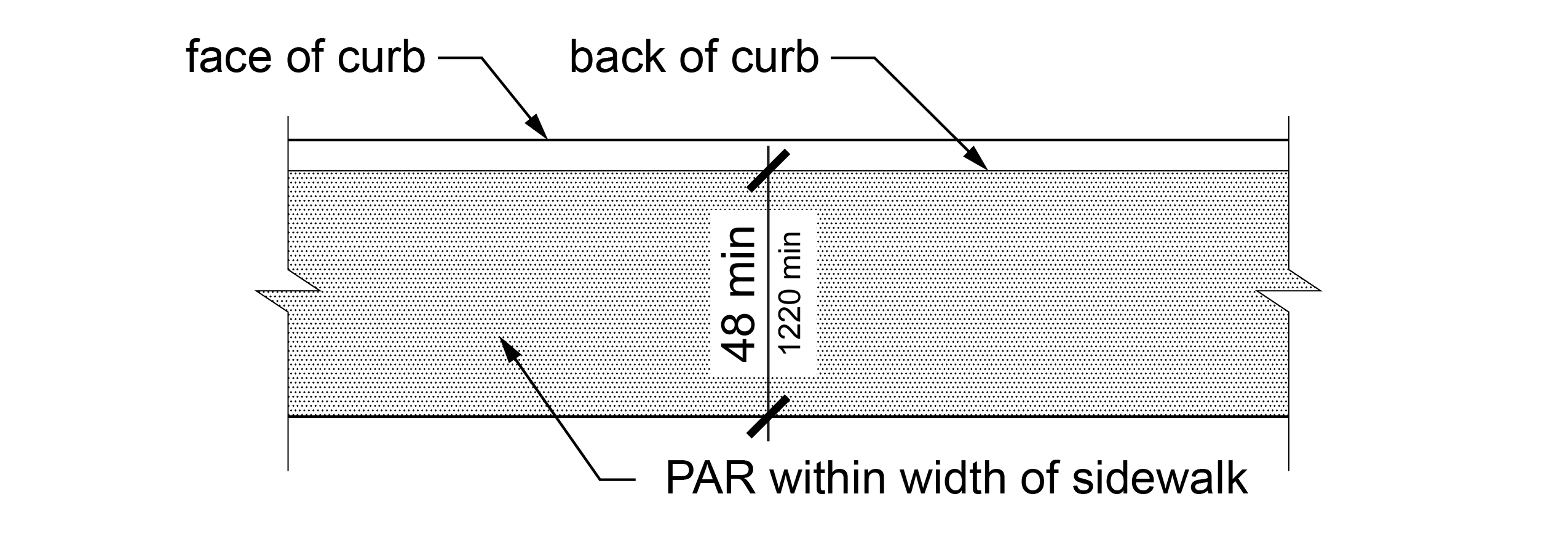
R302.2 Continuous Clear Width
Except as provided in R302.2.1 and R302.2.2, the continuous clear width of pedestrian access routes shall be 48 inches (1220 mm) minimum, exclusive of the width of any curb.
R302.2.1 Medians and Pedestrian Refuge Islands
The clear width of pedestrian access routes crossing medians and pedestrian refuge islands shall be 60 inches (1525 mm) minimum, except that where shared use paths cross medians and pedestrian refuge islands the clear width of the pedestrian access route shall be 60 inches (1525 mm) minimum or at least as wide as the crosswalk, whichever is greater.
R302.2.2 Shared Use Paths
On shared use paths, the clear width of the pedestrian access route shall extend the full width provided for pedestrian circulation on the path. Obstructions, such as bollards, shall not reduce the clear width of the pedestrian access route to less than 48 inches (1220 mm) measured from the edge of the obstruction.
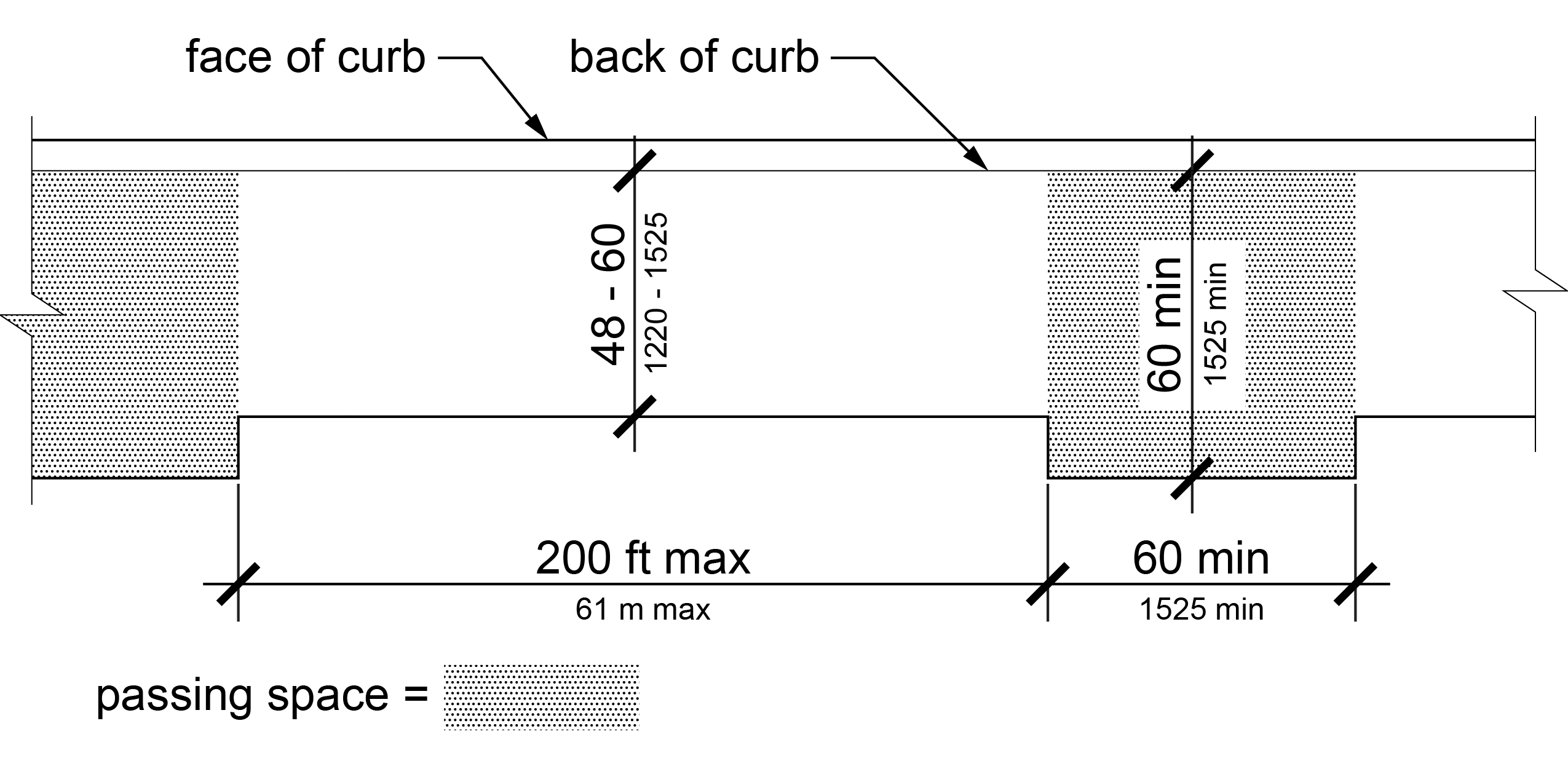
R302.3 Passing Spaces
Where the clear width of pedestrian access routes is less than 60 inches (1525 mm), passing spaces shall be provided at intervals of 200 feet (61 m) maximum. Passing spaces shall be 60 inches (1525 mm) minimum by 60 inches (1525 mm) minimum. Passing spaces and pedestrian access routes are permitted to overlap.
R302.4 Grade
The grade of pedestrian access routes shall comply with R302.4, except the grade of curb ramps and blended transitions shall comply with R304 and the grade of ramps shall comply with R407.
R302.4.1 Within Highway Right-of-Way
Except as provided in R302.4.3, where a pedestrian access route is contained within a highway right-of-way, the grade of the pedestrian access route shall not exceed 1:20 (5.0%).
EXCEPTION: Where the grade established for the adjacent street exceeds 1:20 (5.0%), the grade of the pedestrian access route shall not exceed the grade established for the adjacent street.
R302.4.2 Not Within Highway Right-of-Way
Where a pedestrian access route is not contained within a highway right-of-way, the grade of the pedestrian access route shall not exceed 1:20 (5.0%).
R302.4.3 Within a Crosswalk
Where a pedestrian access route is contained within a crosswalk, the grade of the pedestrian access route shall be 1:20 (5.0%) maximum.
EXCEPTION: Where roadway design requires superelevation greater than 1:20 (5.0%) at the location of a crosswalk, the grade of the pedestrian access route within the crosswalk may be the same as the superelevation.
R302.5 Cross Slope
The cross slope of a pedestrian access route shall comply with R302.5.
R302.5.1 Not Contained Within a Crosswalk
The cross slope of a pedestrian access route not contained within a crosswalk shall be 1:48 (2.1%) maximum.
EXCEPTION: The portion of a pedestrian access route within a street that connects an accessible parallel on-street parking space to the nearest crosswalk at the end of the block face or the nearest midblock crosswalk is not required to comply with R302.5.
R302.5.2 Contained Within a Crosswalk
The cross slope of a pedestrian access route contained within a crosswalk shall comply with R302.5.2.
R302.5.2.1 Crosswalk with Yield or Stop Control Devices
Where a pedestrian access route is contained within a crosswalk at an intersection approach with yield or stop control devices, the cross slope of the pedestrian access route shall be 1:48 (2.1%) maximum.
R302.5.2.2 Crosswalk at Uncontrolled Approach
Where a pedestrian access route is contained within a crosswalk at an uncontrolled approach, the cross slope of the pedestrian access route shall be 1:20 (5.0%) maximum.
R302.5.2.3 Crosswalk with Traffic Control Signal or Pedestrian Hybrid Beacon
Where a pedestrian access route is contained within a crosswalk at an intersection approach controlled by a traffic control signal or pedestrian hybrid beacon, the cross slope of the pedestrian access route shall be 1:20 (5.0%) maximum.
R302.5.2.4 Midblock and Roundabout Crosswalks
The cross slope of a pedestrian access route within a midblock crosswalk or a crosswalk at a roundabout shall not exceed the street grade.
R302.6 Surfaces
The walking surfaces of pedestrian access routes, elements, and spaces that are required to be accessible shall be stable, firm, and slip resistant and shall comply with R302.6.
R302.6.1 Grade Breaks
Grade breaks shall be flush.
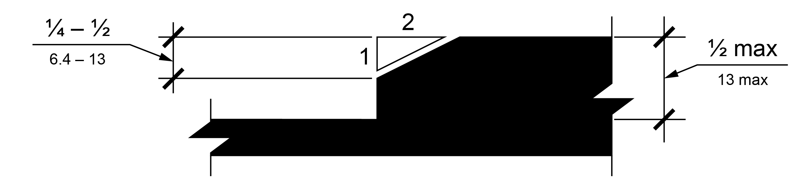
R302.6.2 Changes in Level
Changes in level of ¼ inch (6.4 mm) maximum shall be permitted to be vertical. Changes in level between ¼ inch (6.4 mm) and ½ inch (13 mm) shall be beveled with a slope not steeper than 1:2 (50.0%). Changes in level greater than ½ inch (13 mm) up to 6 inches shall have a 1:12 (8.3%) maximum slope. Changes in level greater than 6 inches (150 mm) shall comply with R407.

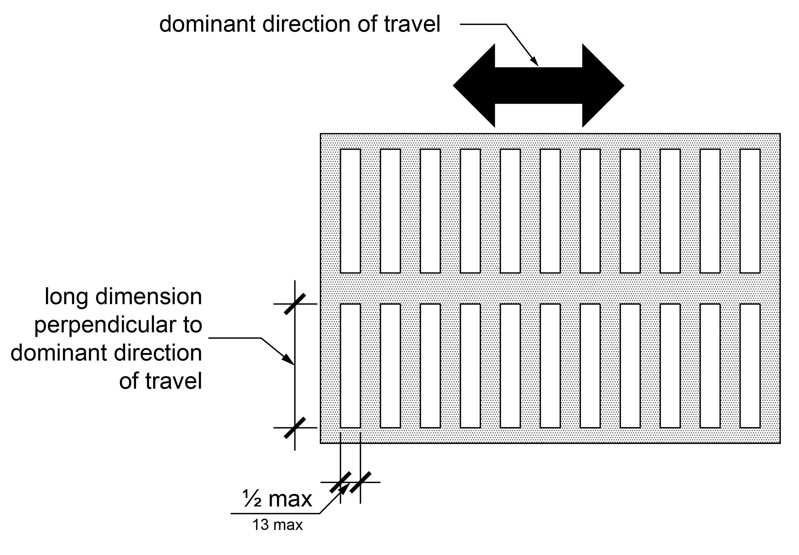
R302.6.3 Horizontal Openings
Horizontal openings in ground surfaces, such as those in gratings and joints, other than flangeway gaps (see R302.6.4), shall not allow passage of a sphere larger than ½ inch (13 mm) in diameter. Except where multiple directions of travel intersect, elongated openings are permitted and shall be placed so that the long dimension is perpendicular to the dominant direction of travel.
R302.6.4 Surfaces at Pedestrian At-Grade Rail Crossings
Surfaces at pedestrian at-grade rail crossings shall comply with R302.6.4.
R302.6.4.1 Surface Alignment
Where a pedestrian access route crosses rails at grade, the pedestrian access route surface shall be level and flush with the top of rail at the outer edges of the rails, and the surface between the rails shall be aligned with the top of rail.
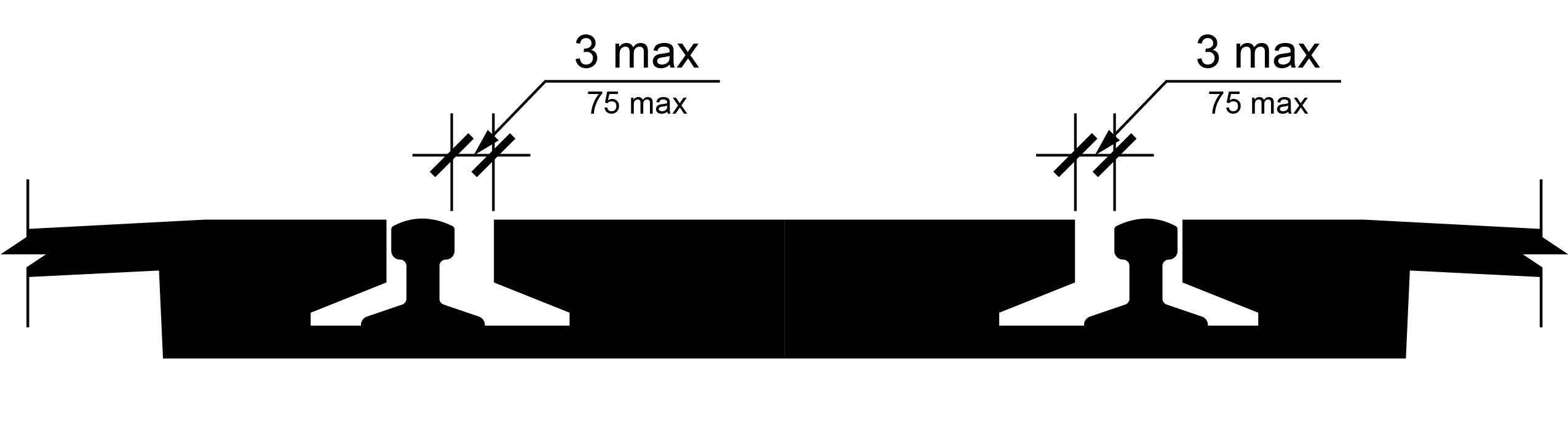
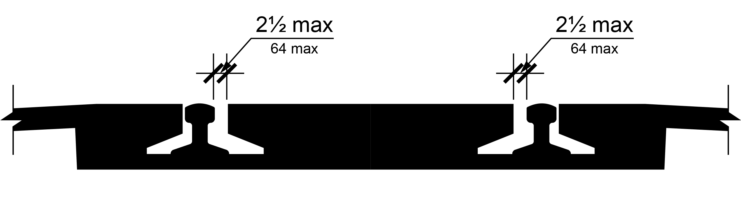
R302.6.4.2 Flangeway Gaps
Flangeway gaps shall comply with R302.6.4.2.
R302.6.4.2.1 Flangeway Gaps at Tracks Subject to FRA Safety Regulations
At pedestrian at-grade rail crossings that cross tracks that are subject to safety regulations at 49 CFR part 213, issued by the Federal Railroad Administration, flangeway gaps shall be 3 inches (75 mm) wide maximum.
R302.6.4.2.2 Flangeway Gaps at Tracks Not Subject to FRA Safety Regulations safety regulations
At pedestrian at-grade rail crossings that cross tracks that are not subject to safety regulations at 49 CFR part 213, issued by the Federal Railroad Administration, flangeway gaps shall be 2½ inches (64 mm) wide maximum.
R303 Alternate Pedestrian Access Routes
R303.1 General
Alternate pedestrian access routes shall comply with R303.
R303.2 Signs
Signs identifying alternate pedestrian access routes shall be provided in advance of decision points and shall comply with R410. Proximity actuated audible signs or other non-visual means within the public right-of-way of conveying the information that identifies the alternate pedestrian access route shall also be provided.
R303.3 Surface
Alternate pedestrian access route surfaces shall comply with R302.6 or shall not be less accessible than the surface of the temporarily closed pedestrian circulation path.
R303.4 Continuous Clear Width
The minimum continuous clear width of alternate pedestrian access routes shall be 48 inches (1220 mm) exclusive of the width of any curb.
EXCEPTION: Where the alternate pedestrian access route utilizes an existing pedestrian circulation path, the width shall not be less than the width of the temporarily closed pedestrian circulation path.
R303.5 Curb Ramp or Blended Transition
Where an alternate pedestrian access route crosses a curb, a curb ramp or blended transition complying with R304 shall be provided.
R303.6 Detectable Edging of Channelizing Devices
Where a channelizing device is used to delineate an alternate pedestrian access route, continuous detectable edging complying with R303.6 shall be provided throughout the length of the route.
EXCEPTION: Where pedestrians or vehicles turn or cross, gaps in the detectable edging are permitted.
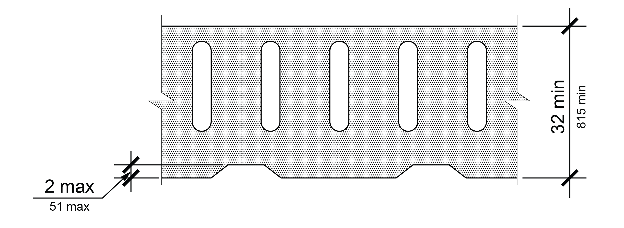
R303.6.1 Top
The top of the top detectable edging shall be no lower than 32 inches (815 mm) above the walking surface and be free of sharp or abrasive surfaces.
R303.6.2 Bottom
The bottom of the bottom detectable edging shall be 2 inches (51 mm) maximum above the walking surface.
R303.7 Pedestrian Signal Heads
Where temporary pedestrian signal heads are provided at a crosswalk that is part of an alternate pedestrian access route, pedestrian pushbuttons or passive detection devices shall be provided and shall comply with R307.
R304 Curb Ramps and Blended Transitions
R304.1 General
Curb ramps and blended transitions shall comply with R304 and have detectable warning surfaces in accordance with R205.
R304.2 Perpendicular Curb Ramps
Perpendicular curb ramps shall comply with R304.2 and R304.5.
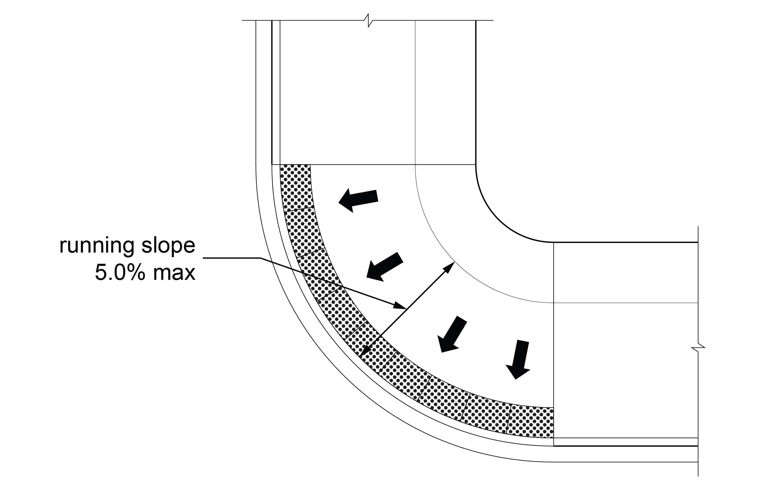
R304.2.1 Running Slope
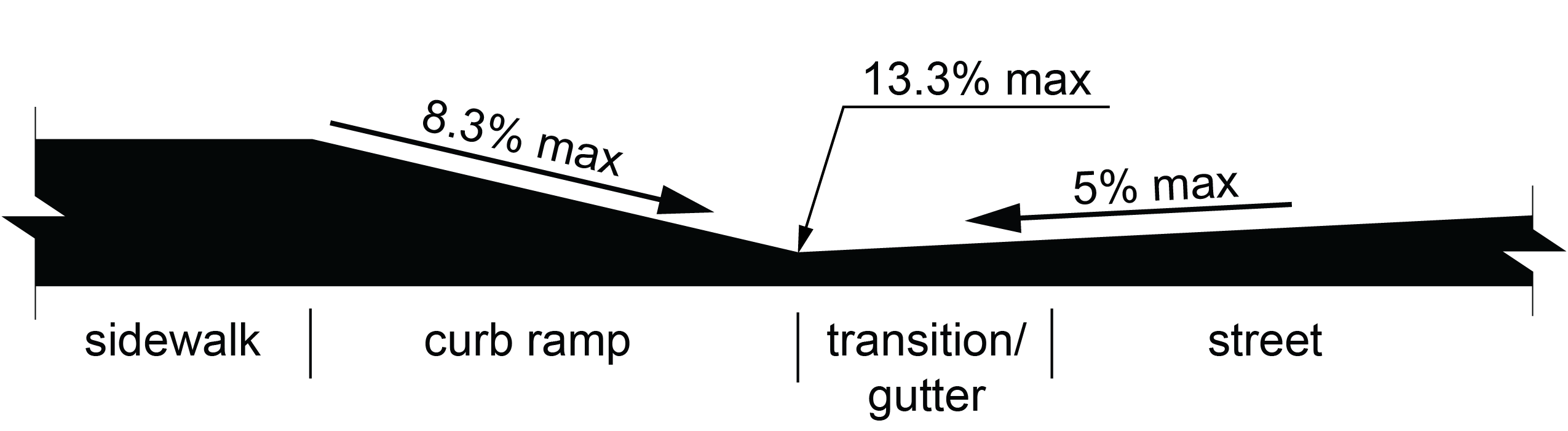
The running slope of a curb ramp shall be perpendicular to the curb or gutter grade break. The running slope of the curb ramp shall be 1:12 (8.3%) maximum.
EXCEPTION: Where the curb ramp length must exceed 15 feet (4.6 m) to achieve a 1:12 (8.3%) running slope, the curb ramp length shall extend at least 15 feet (4.6 m) and may have a running slope greater than 1:12 (8.3%).
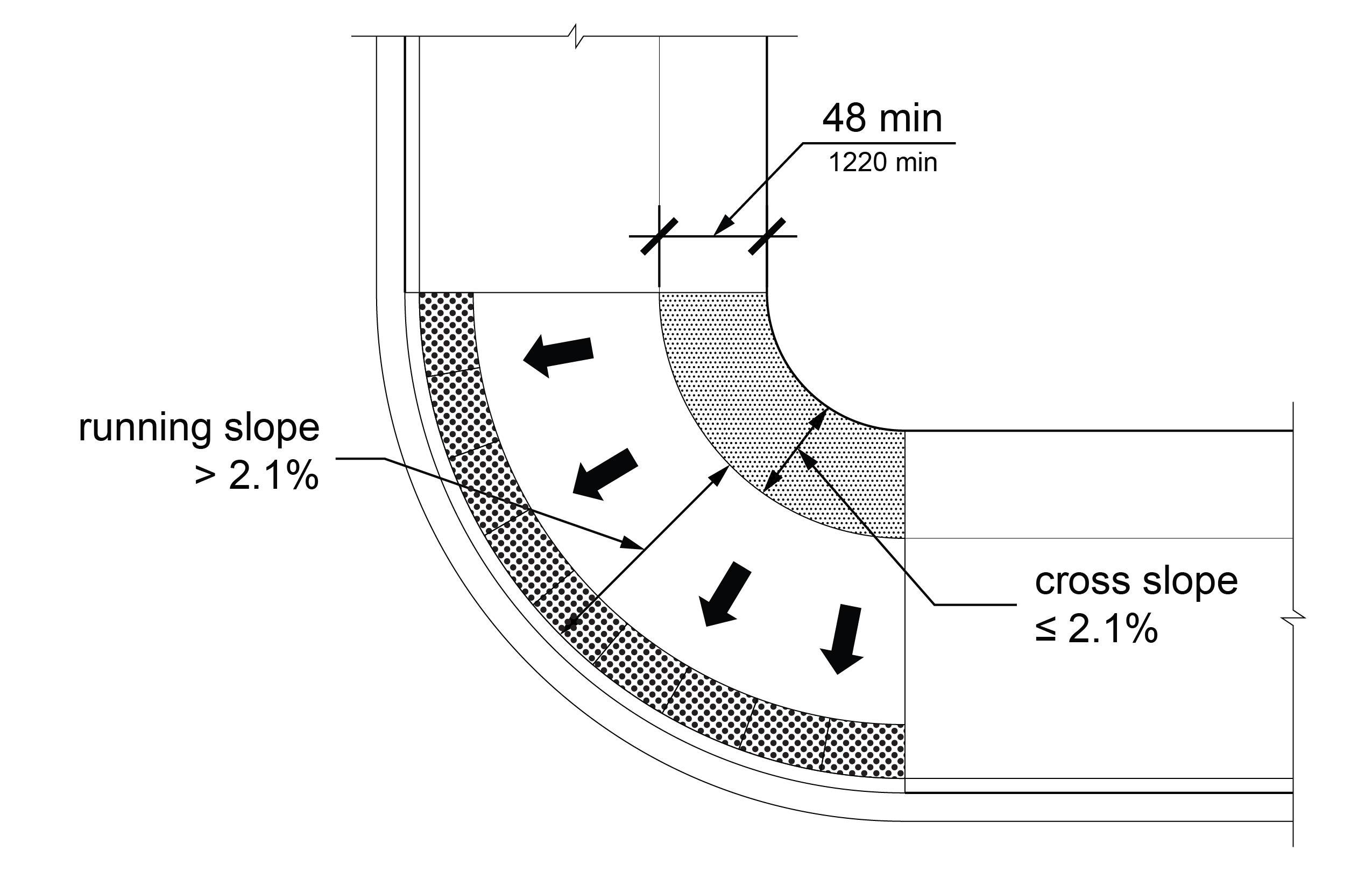
R304.2.2 Cross Slope
The cross slope of a curb ramp run shall be 1:48 (2.1%) maximum.
EXCEPTION: At crosswalks, the cross slope of the curb ramp run shall be permitted to be equal to or less than the cross slope of the crosswalk as specified by R302.5.
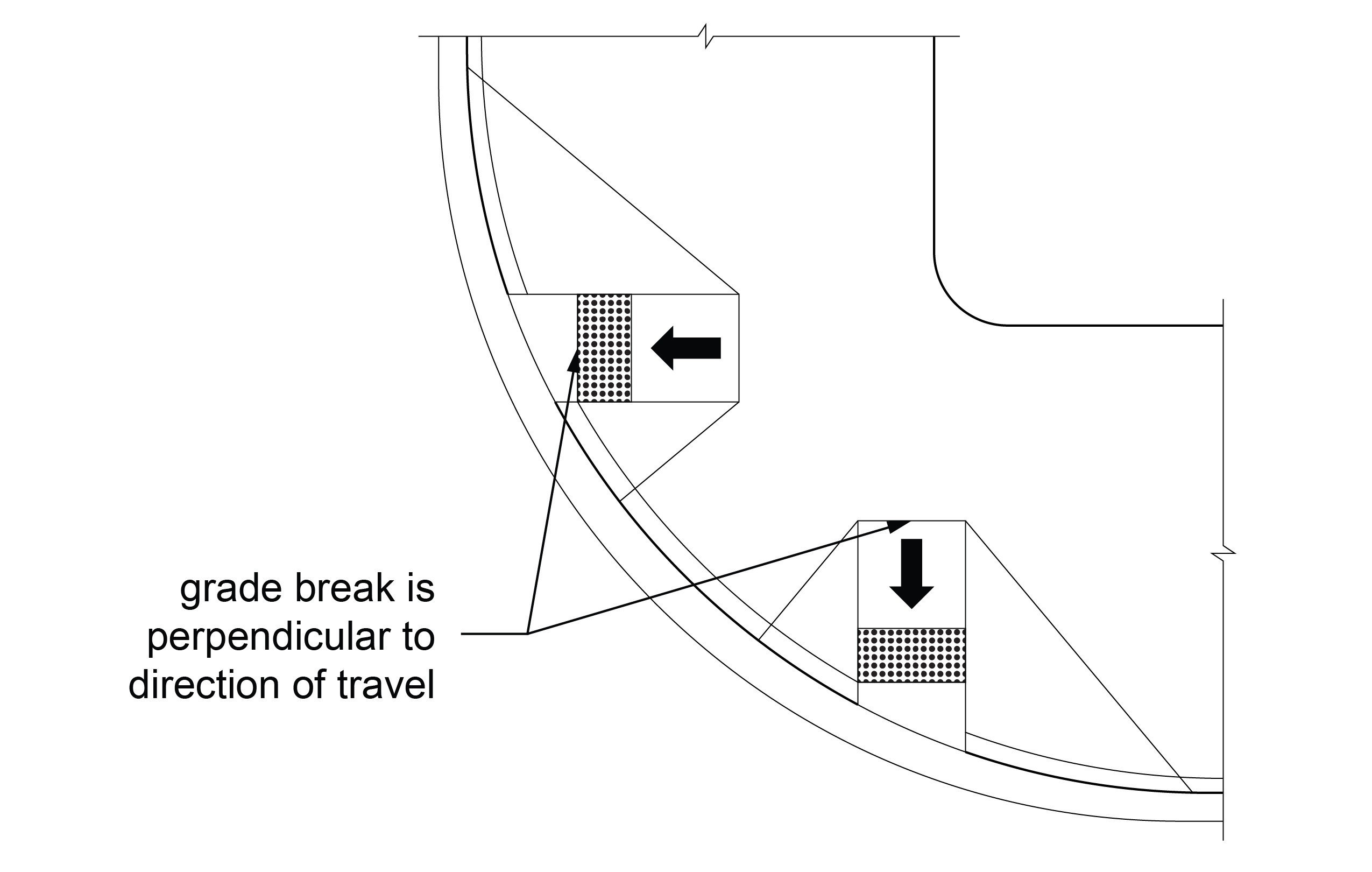
R304.2.3 Grade Breaks
Grade breaks at the top and bottom of a curb ramp run shall be perpendicular to the direction of the curb ramp run. Grade breaks shall not be permitted on the surfaces of curb ramp runs and landings. Surface slopes that meet at grade breaks shall be flush.
R304.2.4 Clear Area
A clear area 48 inches (1220 mm) wide minimum by 48 inches long (1220 mm) minimum shall be provided beyond the bottom grade break of the perpendicular curb ramp run and within the width of the crosswalk. At shared use paths, the clear area shall be as wide as the shared use path. The clear area shall be located wholly outside the vehicle travel lanes, including bicycle lanes, that run parallel to the crosswalk. The running slope of the clear area shall be 1:20 (5.0%) maximum. The cross slope of the clear area shall be as specified by R302.5.
R304.2.5 Landing
When a change in direction is necessary to access a curb ramp from a pedestrian access route, a landing shall be provided at the top of the curb ramp. The landing shall be 48 inches (1220 mm) wide minimum by 48 inches (1220 mm) long minimum. At shared use paths, the landing shall be as wide as the shared use path. Where a landing serves only one curb ramp, the landing slope measured perpendicular to the curb ramp run shall be equal to or less than the cross slope of the curb ramp run, and the landing slope measured parallel to the curb ramp run shall be 1:48 (2.1%) maximum. Where a landing serves two curb ramps, the landing slope in either direction of travel shall not exceed the cross slope of the crosswalk parallel to the direction of travel as specified by R302.5.
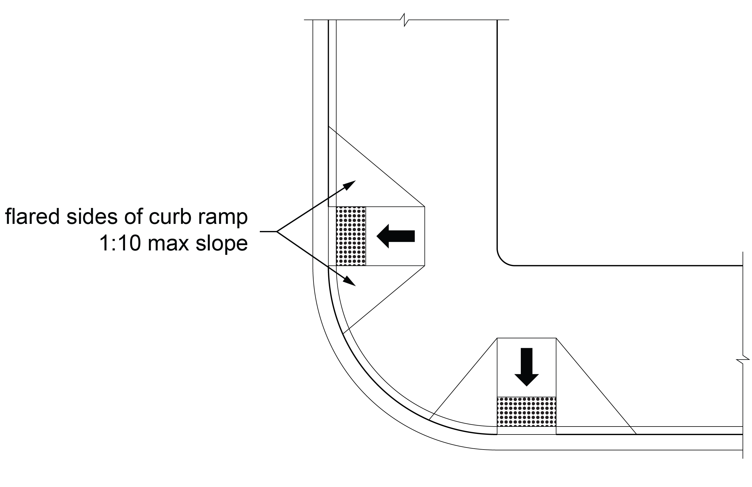
R304.2.6 Side Treatments
Where a pedestrian circulation path crosses the side of a curb ramp, the side of the curb ramp shall be flared. The slope of the flared side shall be 1:10 (10.0%) maximum, measured parallel to the adjacent curb line.
R304.2.7 Connection to Pedestrian Facilities
Perpendicular curb ramps or their landings shall be connected to adjacent pedestrian facilities by pedestrian access routes complying with R302. A transitional segment may be used in the connection.
R304.3 Parallel Curb Ramps
Parallel curb ramps shall comply with R304.3 and R304.5.
R304.3.1 Running Slope
The running slope of the curb ramp run shall be parallel to the curb and shall be 1:12 (8.3%) maximum.
EXCEPTION: Where the curb ramp run length must exceed 15 feet (4.6 m) to achieve a 1:12 (8.3%) running slope, the curb ramp run length shall extend at least 15 feet (4.6 m) and may have a running slope greater than 1:12 (8.3%).
R304.3.2 Cross Slope
The cross slope of the curb ramp run shall be 1:48 (2.1%) maximum.
R304.3.3 Grade Breaks
Grade breaks at the top and bottom of a curb ramp run shall be perpendicular to the direction of the curb ramp run. Grade breaks shall not be permitted on the surfaces of curb ramp runs or landings. Surface slopes that meet at grade breaks shall be flush.
R304.3.4 Landings
Landings shall be provided at the bottom of parallel curb ramps. Landings shall be 48 inches (1220 mm) wide minimum by 48 inches (1220 mm) long minimum. The slope of the landing, measured parallel to the direction of travel on the curb ramp run, shall be permitted to be equal to or less than the slope of the roadway or the cross slope of the crosswalk as specified by R302.5. The cross slope of the landing shall be 1:48 (2.1%) maximum measured perpendicular to the direction of travel on the curb ramp run.
R304.4 Blended Transitions
Blended transitions shall comply with R304.4 and R304.5.
R304.4.1 Running Slope
The running slope of blended transitions shall be 1:20 (5.0%) maximum.
R304.4.2 Cross Slope
The cross slope of blended transitions shall be equal to or less than the cross slope of the crosswalk as specified by R302.5.
R304.4.3 Bypass
Where a blended transition serving more than one pedestrian circulation path has a running slope greater than 1:48 (2.1%), a pedestrian access route shall be provided so that a pedestrian not crossing the street may bypass the blended transition.
R304.5 Common Requirements
Curb ramps and blended transitions shall comply with R304.5.
R304.5.1 Width
The width of curb ramp runs (excluding any flared sides) and blended transitions shall comply with R304.5.1.1 or R304.5.1.2, as applicable.
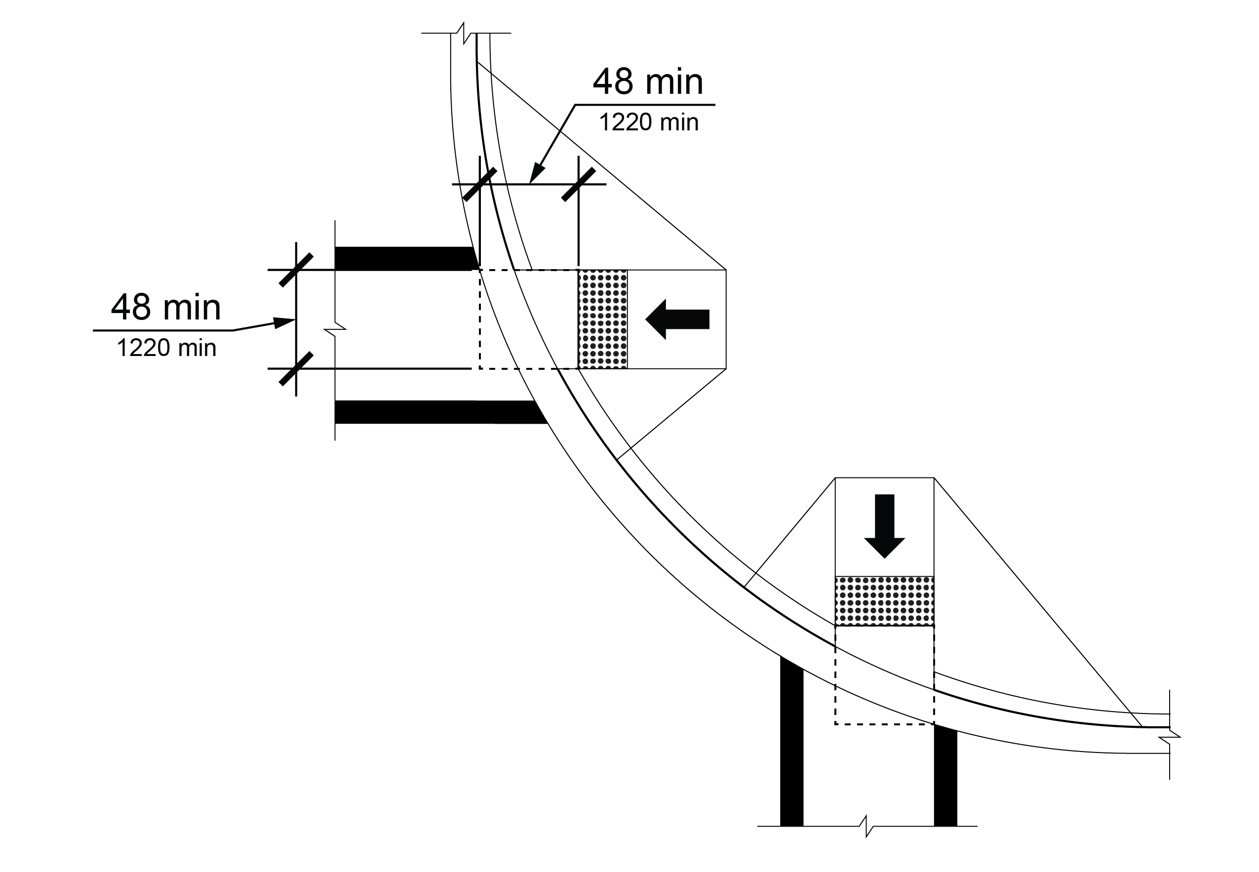
R304.5.1.1 Curb Ramps and Blended Transitions Not on Shared Use Paths
The clear width of curb ramp runs (excluding any flared sides) and blended transitions not on shared use paths shall be 48 inches (1220 mm) minimum.
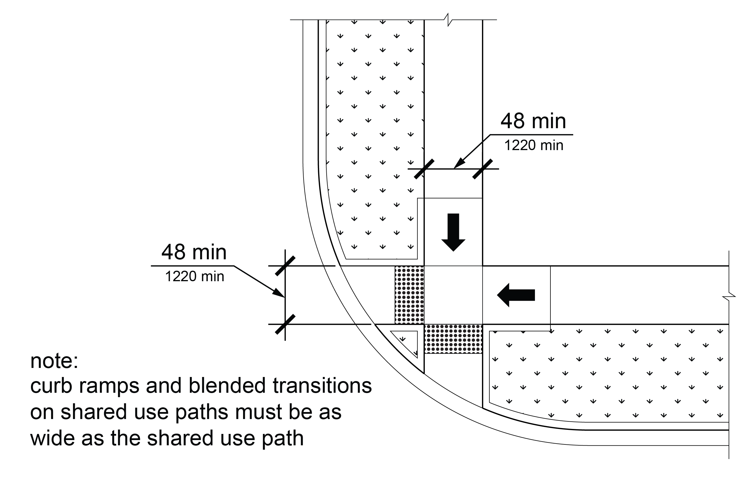
R304.5.1.2 Curb Ramps and Blended Transitions on Shared Use Paths
On shared use paths, the width of curb ramp runs (excluding any flared sides) and blended transitions shall be equal to the width of the shared use path.
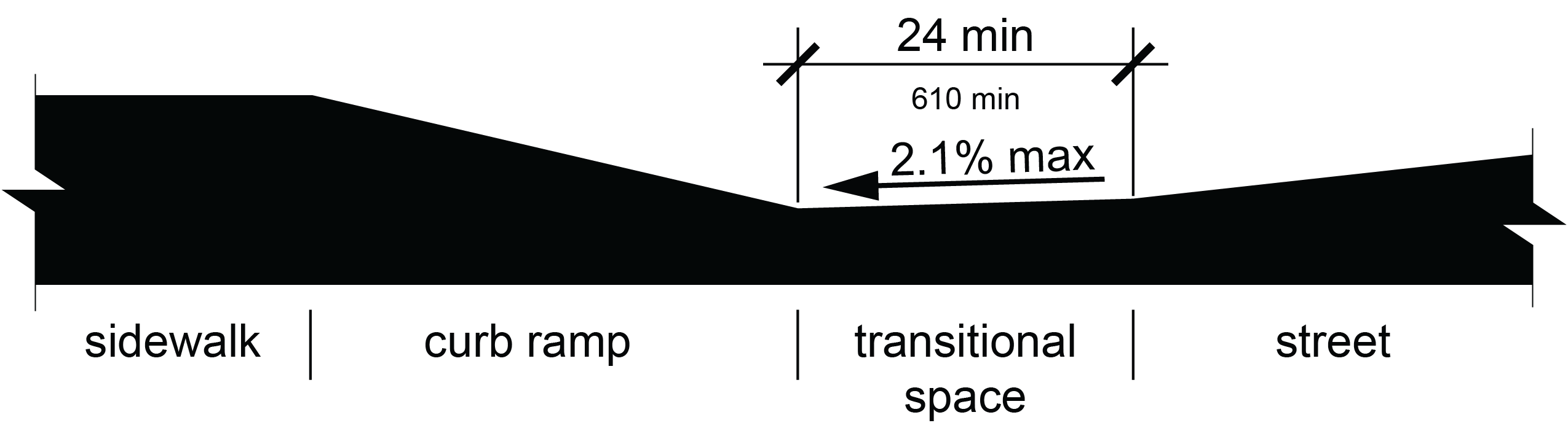
R304.5.2 Change of Grade
At gutters and streets where a change of grade occurs adjacent to curb ramps and blended transitions, the change of grade shall comply with the requirements contained in (A) or (B) below:
A. The change of grade shall not exceed 13.3 percent, or
B. A transitional space shall be provided at the bottom of the running slope of the curb ramp run or blended transition. The transitional space shall extend 24 inches (610 mm) minimum in the direction of pedestrian travel and the full width of the curb ramp run or blended transition. Transitional spaces shall have running slopes of 1:48 (2.1%) maximum and cross slopes no greater than the cross slope of the crosswalk as specified by R302.5.
R304.5.3 Crosswalks
Perpendicular curb ramp runs, parallel curb ramp landings, and 48 inches (1220 mm) minimum width of blended transitions, except those at shared use paths, shall be contained wholly within the width of the crosswalks they serve. At shared use paths, the full width of a perpendicular curb ramp run, parallel curb ramp landing, or the blended transition shall be contained wholly within the width of the crosswalk it serves.
R304.5.4 Surfaces
Surfaces of curb ramps and blended transitions shall comply with R302.6 except that changes in level are not permitted.
R305 Detectable Warning Surfaces
R305.1 General
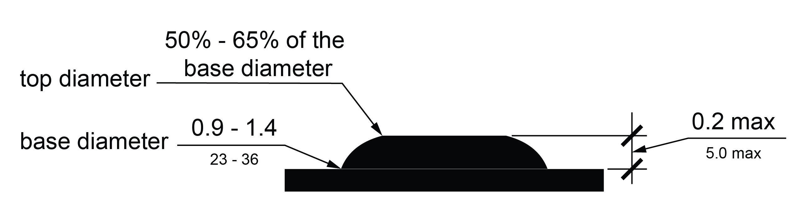
Detectable warning surfaces shall consist of truncated domes in a square or radial grid pattern and shall comply with R305.
R305.1.1 Dome Size
The truncated domes shall have a base diameter of 0.9 inches (23 mm) minimum and 1.4 inches (36 mm) maximum, a top diameter of 50 percent of the base diameter minimum and 65 percent of the base diameter maximum, and a height of 0.2 inches (5.1 mm). When detectable warning surface tiles are cut to fit, partial domes are permitted along the cut edges.
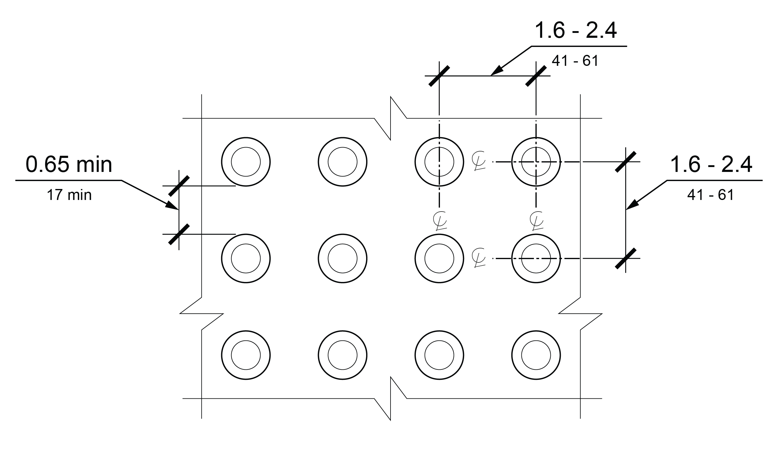
R305.1.2 Dome Spacing
The truncated domes shall have a center-to-center spacing of 1.6 inches (41 mm) minimum and 2.4 inches (61 mm) maximum, and a base-to-base spacing of 0.65 inches (17 mm) minimum, measured between the most adjacent domes.
EXCEPTIONS: 1. When detectable warning surfaces are cut to fit, center-to-center spacing measured between domes adjacent to cut edges shall not exceed twice the normal spacing between domes not adjacent to cut edges.
2. Dome spacing requirements do not apply at a gap in a detectable warning surface at an expansion joint provided that the detectable warning surface aligns with both edges of the expansion joint.
R305.1.3 Contrast
Detectable warning surfaces shall contrast visually with adjacent walking surfaces, either light-on-dark or dark-on-light.
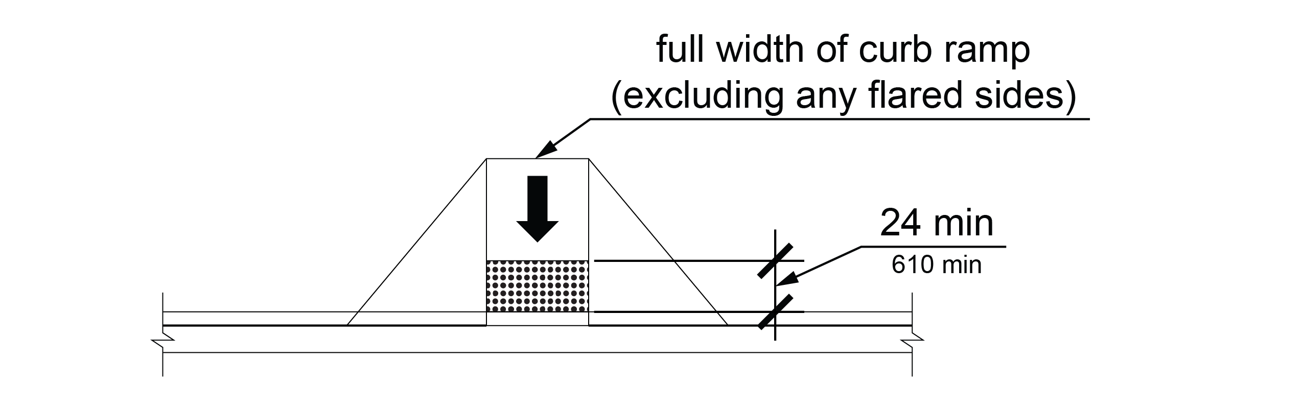
R305.1.4 Surface Size
Detectable warning surfaces shall extend 24 inches (610 mm) minimum in the direction of pedestrian travel. The width of detectable warning surfaces shall be as follows:
A. At curb ramps and blended transitions, detectable warning surfaces shall extend the full width of the curb ramp run (excluding any flared sides), blended transition, or landing.
B. At cut-through pedestrian refuge islands, detectable warning surfaces shall extend the full width of the pedestrian circulation path opening.
C. At pedestrian at-grade rail crossings not located within a street, detectable warning surfaces shall extend the full width of the pedestrian circulation path.
D. Where required at boarding platforms, detectable warning surfaces shall extend the full length of the unprotected areas of the platform.
E. At boarding and alighting areas at sidewalk or street level transit stops for rail vehicles, detectable warning surfaces shall extend the full length of the unprotected area of the transit stop.
R305.2 Location
The location of detectable warning surfaces shall comply with R305.2. Where a concrete border is required for proper installation of a detectable warning surface, a concrete border not exceeding 2 inches (51 mm) shall be permitted on all sides of the detectable warning surface except between the detectable warning surface and the edge of pavement where a setback is already permitted.
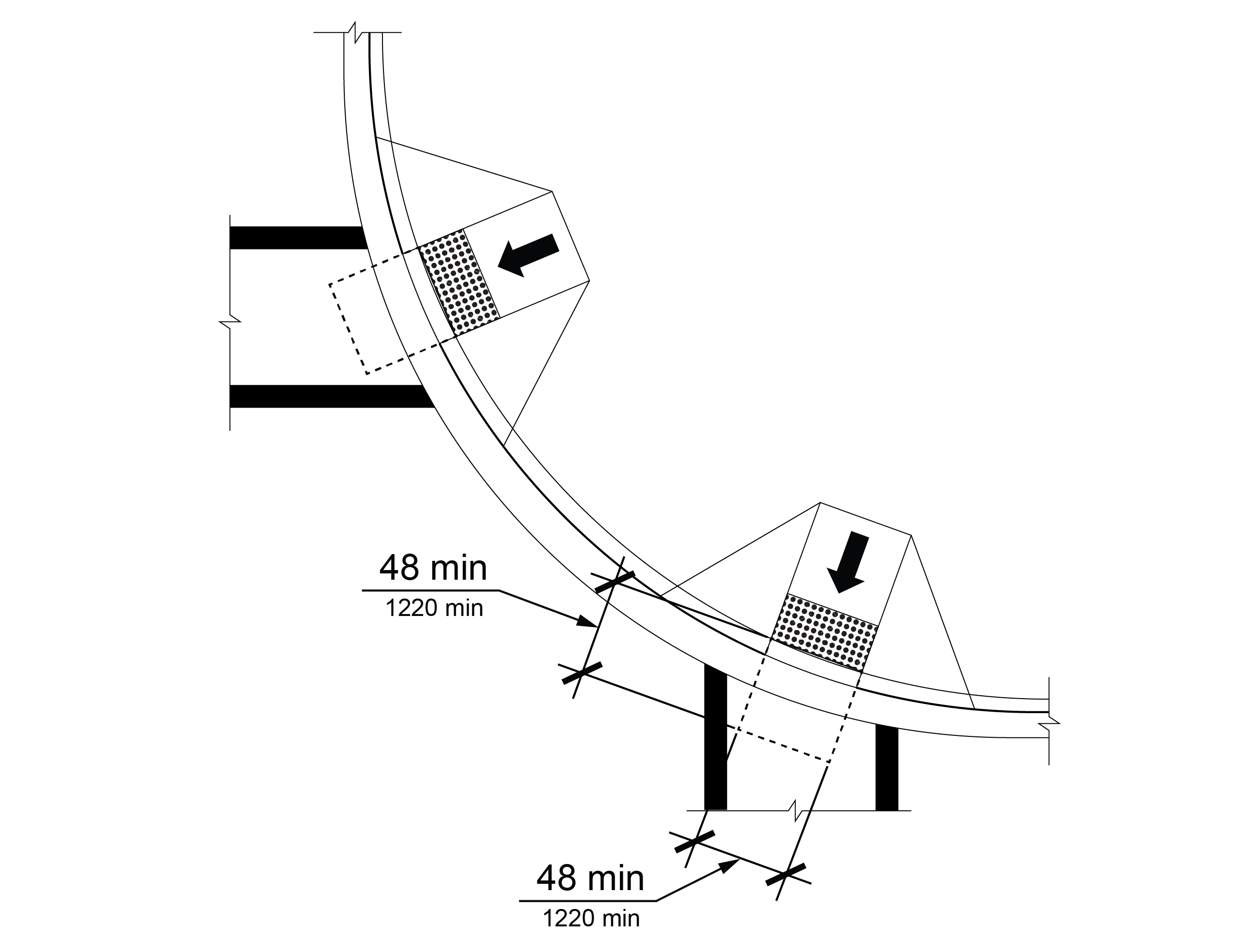
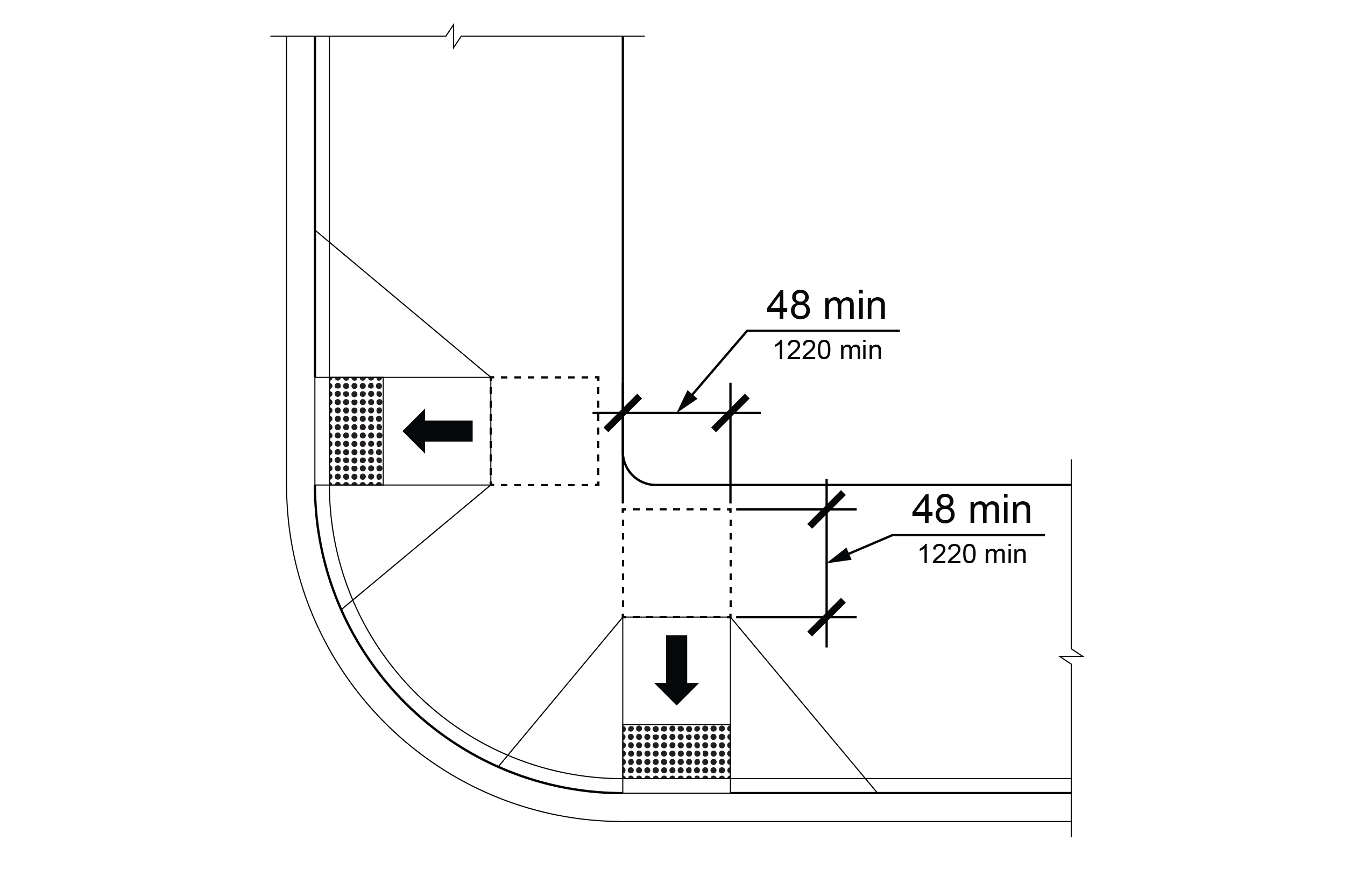
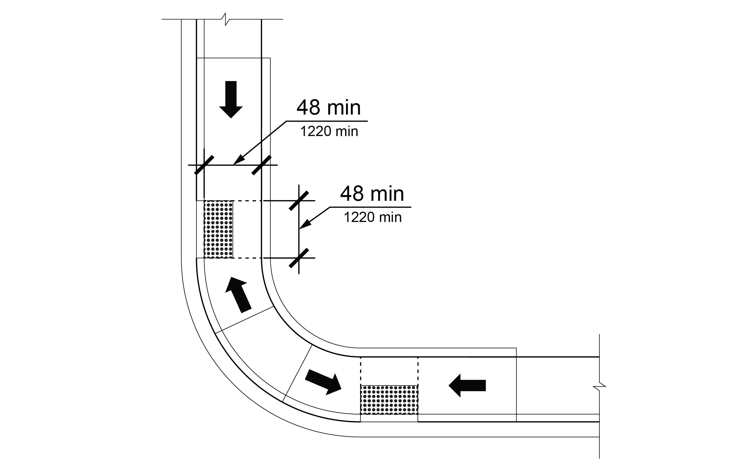
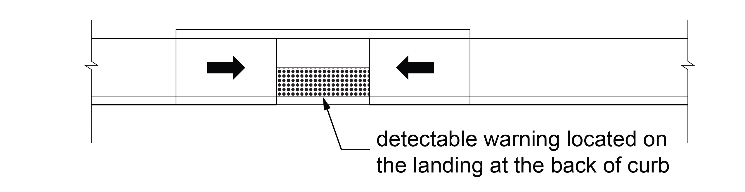
R305.2.1 Perpendicular Curb Ramps
On perpendicular curb ramps, detectable warning surfaces shall be located as follows:
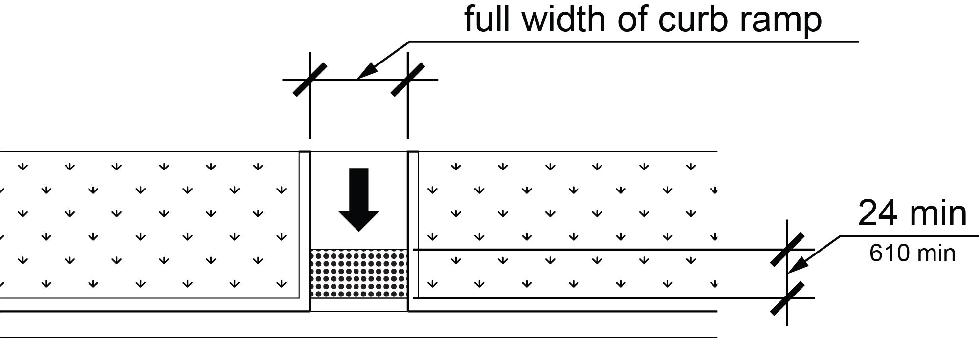
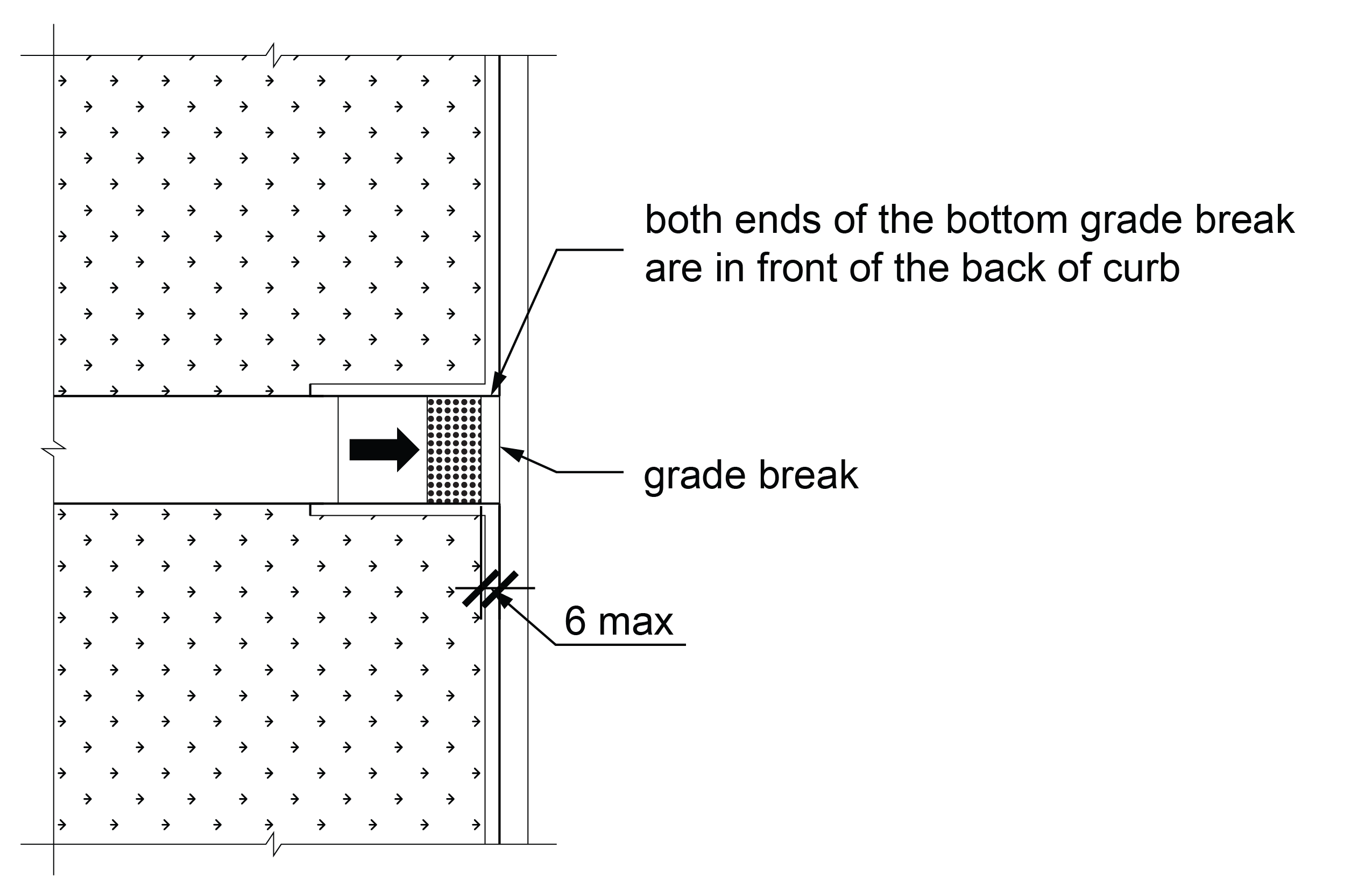
A. Where the ends of the bottom grade break are in front of the back of curb or at the edge of pavement where there is no curb, the detectable warning surface shall be placed at the back of curb or no greater than 6 inches (150 mm) from the edge of pavement where there is no curb.
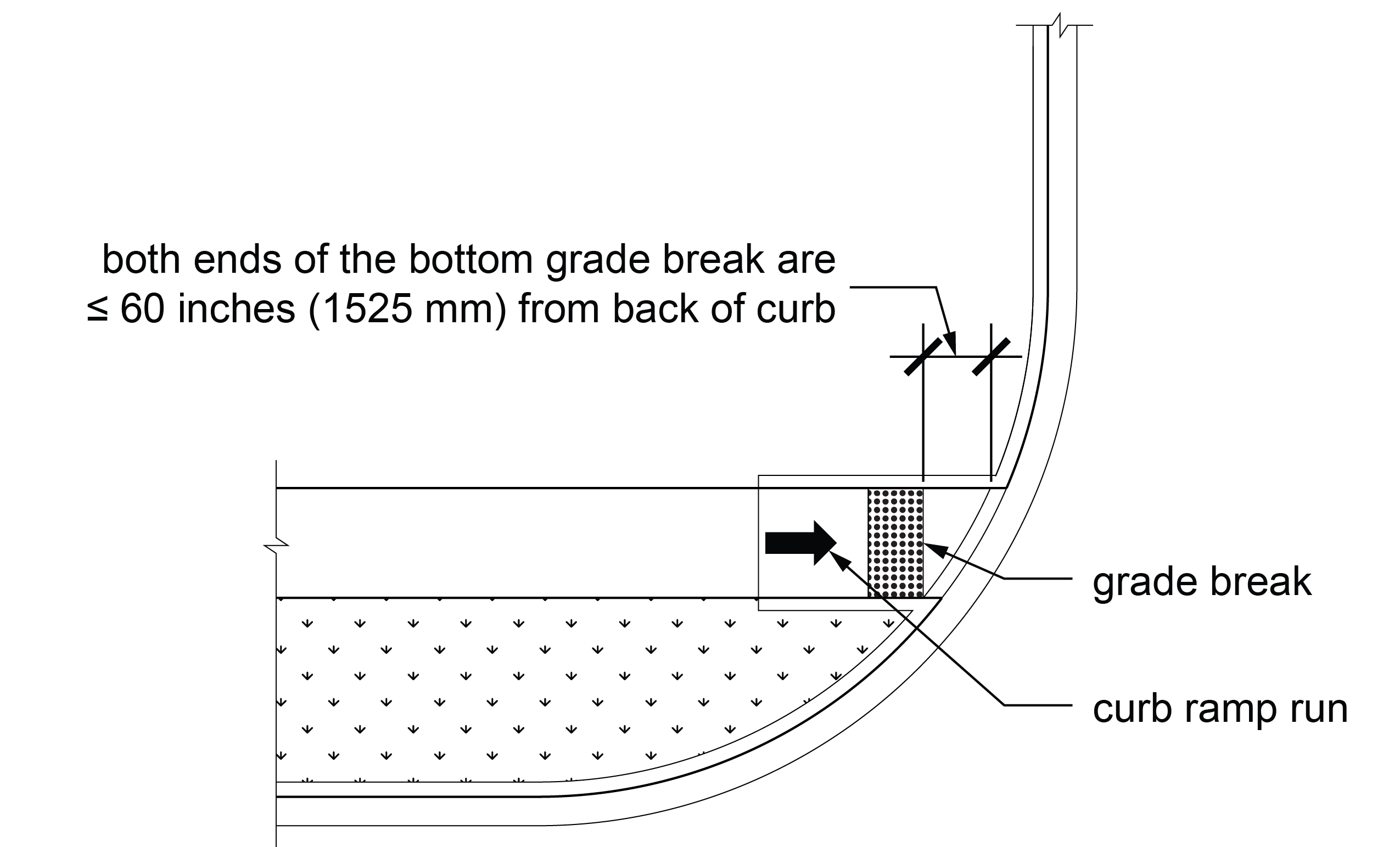
B. Where the ends of the bottom grade break are behind the back of curb or edge of pavement where there is no curb and the distance from both ends of the bottom grade break to the back of curb or edge of pavement where there is no curb is 60 inches (1525 mm) or less, the detectable warning surface shall be placed on the ramp run at the bottom grade break.
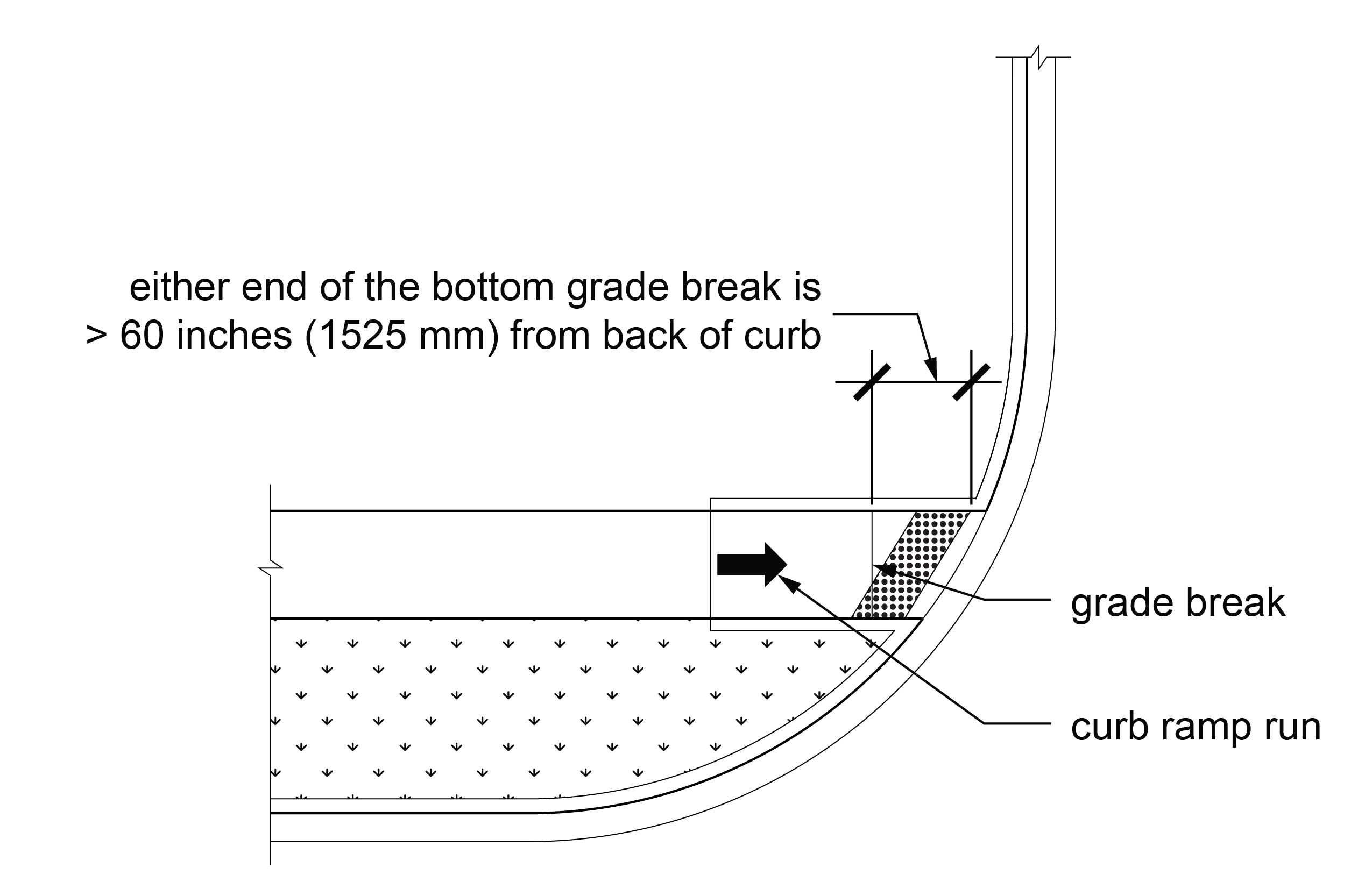
C. Where the ends of the bottom grade break are behind the back of curb or edge of pavement where there is no curb and the distance from either end of the bottom grade break to the back of curb or edge of pavement where there is no curb is more than 60 inches (1525 mm), the detectable warning surface shall be placed on the clear area so that both front corners of the detectable warning surfaces are at the back of curb or no greater than 6 inches (150 mm) from the edge of pavement where there is no curb.
R305.2.2 Parallel Curb Ramps
On parallel curb ramps, detectable warning surfaces shall be located on the landing at either the back of curb or the edge of pavement where there is no curb.
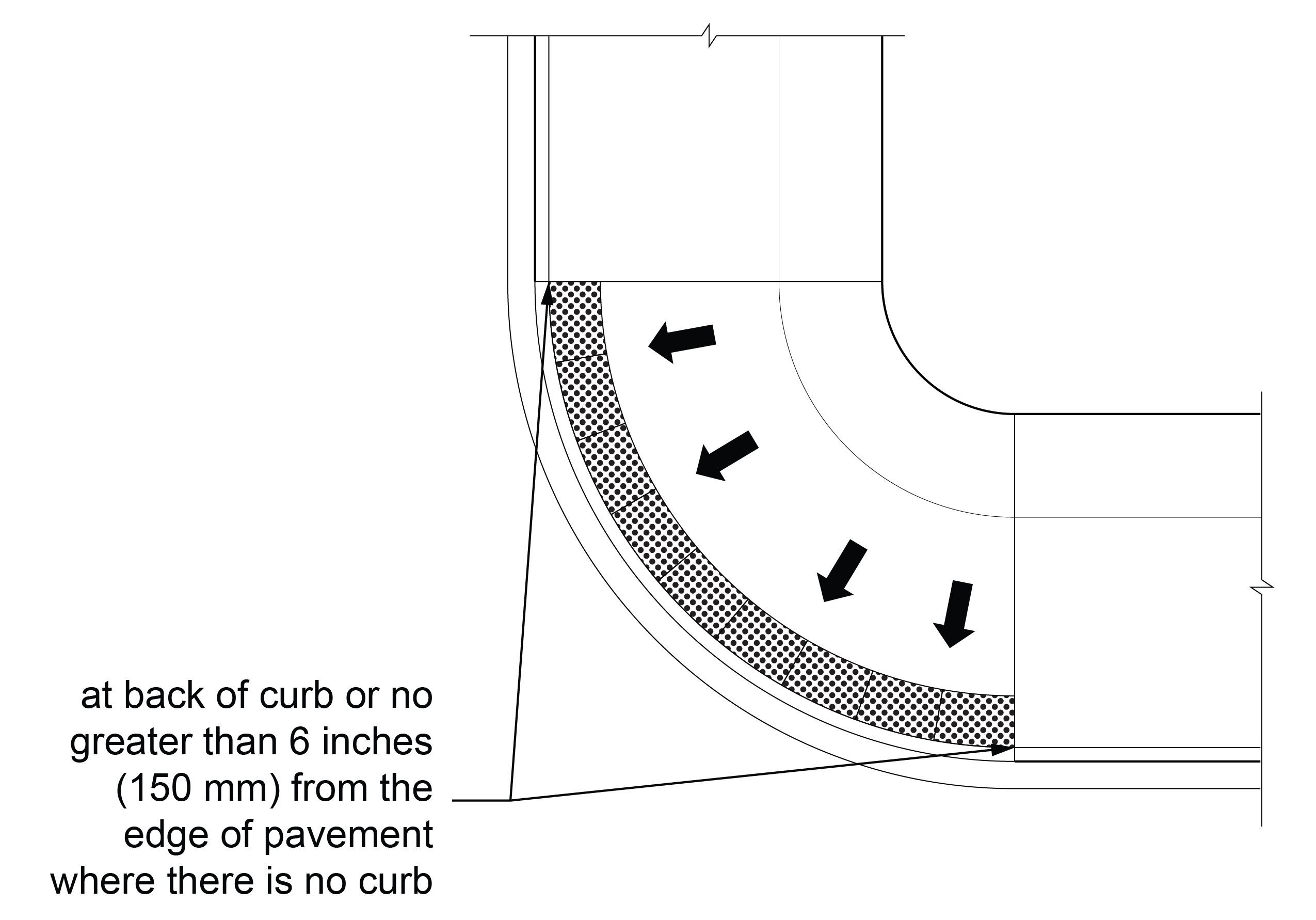
R305.2.3 Blended Transitions
On blended transitions, detectable warning surfaces shall be located on the blended transition so that both front corners of the detectable warning surfaces are at the back of curb or no greater than 6 inches (150 mm) from the edge pavement where there is no curb.
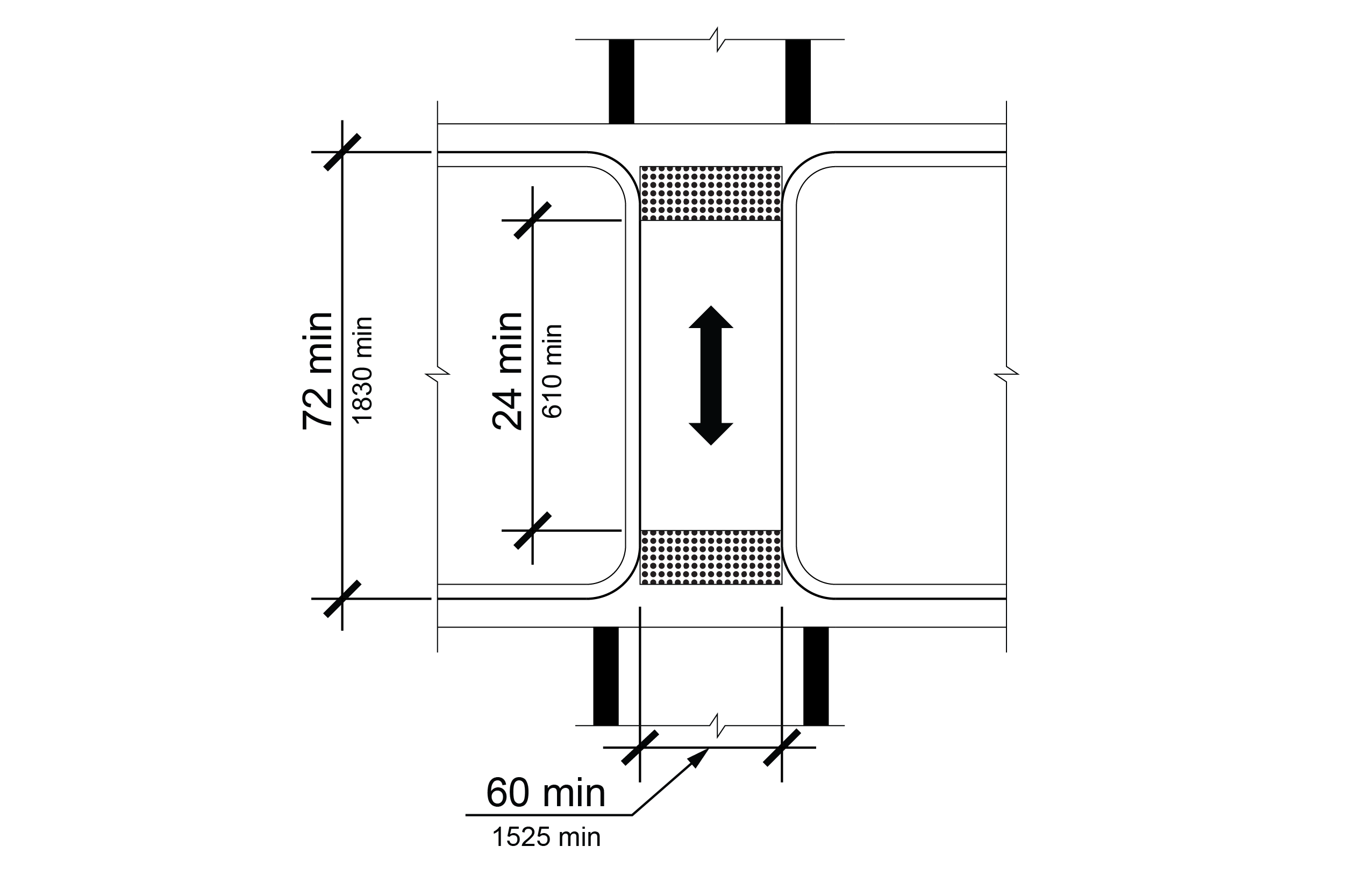
R305.2.4 Pedestrian Refuge Islands
At cut-through pedestrian refuge islands, detectable warning surfaces shall be located no greater than 6 inches (150 mm) from the edges of the pedestrian refuge island or at back of curb and shall be separated by a 24 inch (610 mm) minimum length of surface in the direction of travel without detectable warning surfaces.
R305.2.5 Pedestrian At-Grade Rail Crossings
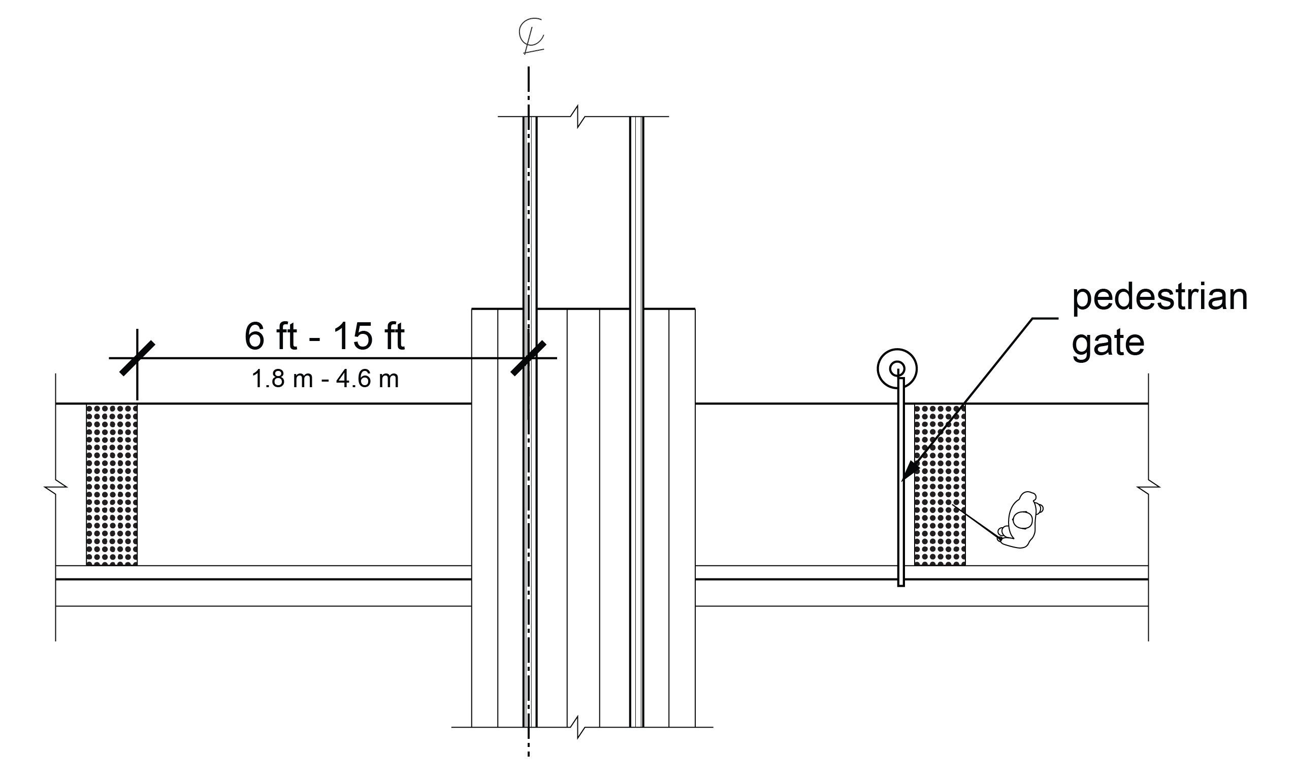
At pedestrian at-grade rail crossings not located within a street, detectable warning surfaces shall be located on each side of the rail crossing. The edge of the detectable warning surface nearest the rail crossing shall be 6 feet (1.8 m) minimum and 15 feet (4.6 m) maximum from the centerline of the nearest rail. Where pedestrian gates are provided, detectable warning surfaces shall be located on the side of the gate opposite the rail. Pedestrian gates shall not overlap detectable warning surfaces.
R305.2.6 Boarding Platforms
At boarding platforms for transit vehicles, detectable warning surfaces shall be located at the boarding edge of the platform.
EXCEPTION: Where a curb is present at the boarding edge of the platform, the detectable warning surface may be placed at the back of curb.
R305.2.7 Sidewalk and Street-Level Rail Boarding and Alighting Areas
At boarding and alighting areas at sidewalk or street-level transit stops for rail vehicles, detectable warning surfaces shall be located at the edge of the boarding and alighting area closest to the rail vehicles.
R305.2.8 Driveways
Where driveways are controlled with yield or stop control devices or traffic signals, detectable warning surfaces shall be provided on the pedestrian circulation path where the pedestrian circulation path meets the driveway.
R306 Crosswalks
R306.1 General
Crosswalks shall comply with R306.
R306.2 Pedestrian Signal Phase Timing
Where a traffic control signal with pedestrian signal indications is provided at a crosswalk, pedestrian signal phase timing shall be based on a pedestrian clearance time that is calculated using a pedestrian walking speed of 3.5 ft/s (1.1 m/s) or less from the location of the pedestrian push button to a pedestrian refuge island or the far side of the traveled way. The walk interval shall be 7 seconds minimum. Where the pedestrian clearance time is calculated to a pedestrian refuge island, an additional pedestrian push button or passive detection device shall be provided on the pedestrian refuge island.
EXCEPTION: If a passive pedestrian detection device is used to automatically adjust the pedestrian clearance time based on the pedestrian’s actual clearance of the crosswalk, a faster walking speed may be used.
R306.3 Accessible Walk Indication
An accessible walk indication complying with R308.2 shall have the same duration as the walk interval.
EXCEPTION: Where the pedestrian signal rests in walk, the accessible walk indication may be limited to the first 7 seconds of the walk interval. If the pedestrian signal is resting in walk and there is sufficient time remaining to provide an accessible walk interval before the beginning of the pedestrian change interval, the accessible walk indication may be recalled by a button press.
R306.4 Roundabouts
Where pedestrian circulation paths are provided at roundabouts, they shall comply with R306.4.
R306.4.1 Edge Detection
The street side edge of the pedestrian circulation path at the approach and along the circulatory roadway of the roundabout shall comply with R306.4.1.1 where not attached to the curb, or R306.4.1.2 where attached to the curb. Detectable warning surfaces shall not be used for roundabout edge detection.
R306.4.1.1 Separation
Where pedestrian crossing is not intended, the pedestrian circulation path shall be separated from the curb, crosswalk to crosswalk, with landscaping or other nonprepared surface 24 inches (610 mm) wide minimum.
R306.4.1.2 Vertical Edge Treatment
Where pedestrian crossing is not intended, a curb-attached pedestrian circulation path shall have a continuous and detectable vertical edge treatment along the street side of the pedestrian circulation path, from crosswalk to crosswalk. The bottom edge of the vertical edge treatment shall be 15 inches (380 mm) maximum above the pedestrian circulation path.
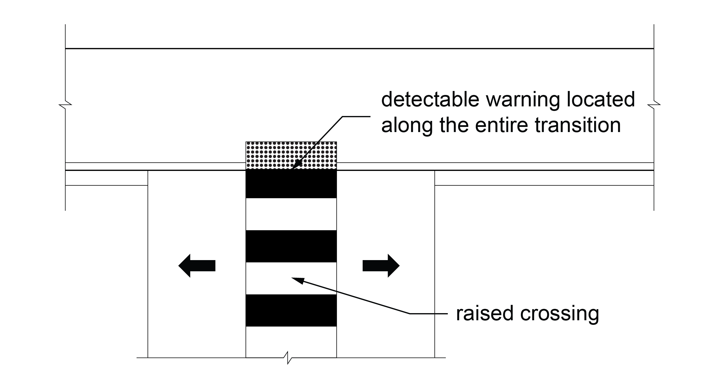
R306.4.2 Crosswalk Treatments
Each multi-lane segment of the roundabout containing a crosswalk shall provide a crosswalk treatment consisting of one or more of the following: a traffic control signal with a pedestrian signal head; a pedestrian hybrid beacon; a pedestrian actuated rectangular rapid flashing beacon; or a raised crossing.
R306.5 Channelized Turn Lanes
Crosswalks at multi-lane channelized turn lanes shall provide treatments consisting of one or more of the following: a traffic control signal with a pedestrian signal head; a pedestrian hybrid beacon; a pedestrian actuated rectangular rapid flashing beacon; or a raised crossing.
R307 Pedestrian Push Buttons and Passive Pedestrian Detection
R307.1 General
Pedestrian push buttons and passive pedestrian detection devices shall comply with R307. Operable parts of pedestrian push buttons shall comply with R403.
R307.2 Activation
Pedestrian push buttons and passive detection devices shall activate the accessible pedestrian signals and, where applicable, the walk interval.
R307.3 Extended Push Button Press
Where an extended push button press is used to provide any additional features, a push button press of less than one second shall actuate only the pedestrian timing and any associated accessible walk indication, and a push button press of one second or more shall actuate the pedestrian timing, any associated accessible walk indication, and any additional features. If additional crossing time is provided by means of an extended pushbutton press, a sign so indicating shall be mounted adjacent to or integral with the pedestrian push button.
R307.4 Location
Pedestrian push buttons shall be located no greater than 5 feet from the side of a curb ramp run or the edge of the farthest associated crosswalk line from the center of the intersection. Pedestrian push buttons shall be located between 1.5 and 10 feet from the edge of the curb or pavement.
R307.4.1 Two Pedestrian Push Buttons on Same Corner
Where two pedestrian push buttons are provided on the same corner, they shall be 10 feet or more apart.
EXCEPTION: In alterations, where technically infeasible to provide 10 feet separation between pedestrian push buttons on the same corner, a pedestrian push button information message complying with R308.3.2 shall be provided.
R307.5 Push Button Orientation
The face of the push button shall be parallel to its associated crosswalk.
R307.6 Audible and Vibrotactile Walk Indications for Pedestrian Signal Heads
Pedestrian push buttons or passive detection devices shall activate audible and vibrotactile walk indications complying with R308.
R307.7 Audible and Vibrotactile Indication for Pedestrian Activated Warning Devices Without a Walk Indication
Where a pedestrian push button or a passive detection device is provided for pedestrian activated warning devices, such as rectangular rapid flashing beacons, the pedestrian push button or passive detection device shall activate a speech message that indicates the status of the beacon in lieu of an audible walk indication. The speech message volume shall comply with R308.4. Where a pedestrian push button is provided, it shall not include vibrotactile features indicating a walk interval.
R307.8 Locator Tone
Pedestrian push buttons shall incorporate a locator tone complying with R307.8.
R307.8.1 Duration
Locator tones shall have a duration of 0.15 seconds or less and repeat at one-second intervals except when another audible indication from the same device is active. When another audible indication from the same device is active, the locator tone shall be silenced.
EXCEPTION: A locator tone may be silenced if a passive detection system activates the locator tone when a pedestrian is within a 12-foot radius of the pedestrian push button.
R307.8.2 Locator Tone in Response to Ambient Sound
Pedestrian push button locator tones shall be intensity responsive to ambient sound and shall be audible 6 to 12 feet from the push button, or to the building line, whichever is less. The push button locator tone shall be louder than ambient sound up to a maximum volume of 5 dBA louder than ambient sound. Automatic volume adjustment in response to ambient traffic sound level shall be a maximum volume of 100 dBA.
R307.8.3 Locator Tone and Audible Beaconing
Where audible beaconing is used, the volume of the push button locator tone during the pedestrian change interval of the called pedestrian phase shall be increased and operated in one of the following ways:
A. The louder audible walk indication and louder locator tone comes from the far end of the crosswalk, as pedestrians cross the street;
B. The louder locator tone comes from both ends of the crosswalk; or
C. The louder locator tone comes from an additional speaker that is aimed at the center of the crosswalk and that is mounted on a pedestrian signal head.
R307.8.4 Locator Tone and Traffic Control Signal in Flashing Mode
When the traffic control signal is operating in a flashing mode, pedestrian push button locator tones shall remain active, and the pedestrian push button shall activate a speech message that communicates the operating mode of the traffic control signal. Where traffic control signals or pedestrian hybrid beacons are activated from a flashing or dark mode to a stop-and-go mode by pedestrian actuations, a speech message communicating the operating status of the traffic control signal is not required.
R307.9 Tactile Arrow
Pedestrian push buttons shall have a tactile arrow with high visual contrast that is aligned parallel to the direction of travel on their associated crosswalks.
R308 Accessible Pedestrian Signal Walk Indications
R308.1 General
Accessible pedestrian signal walk indications shall comply with R308.
R308.2 Audible and Vibrotactile Walk Indications
Accessible pedestrian signals shall have an audible and vibrotactile walk indication during the walk interval only. The audible walk indication shall be audible from the beginning of the associated crosswalk. Following the audible and vibrotactile walk indication and during the pedestrian change interval, accessible pedestrian signals shall revert to the pedestrian push button locator tone.
R308.3 Audible Walk Indications
Audible walk indications shall comply with R308.3.
R308.3.1 Percussive Tone
Where an accessible pedestrian signal is provided at a single crossing or where two accessible pedestrian signals are 10 feet or greater from each other at a corner, the audible walk indication shall be a percussive tone and repeat eight to ten ticks per second with multiple frequencies and a dominant component at 880 Hz.
R308.3.2 Speech Walk Message
In alterations, where it is technically infeasible to provide 10 feet separation between pedestrian push buttons on the same corner, the audible walk indication for each signal shall be a speech walk message that complies with R308.3.2.
R308.3.2.1 Speech Information Message when Walk Interval is Not Timing
Where speech push button information messages are made available at a pretimed signal or by actuating the accessible pedestrian push button or passive detection device, they shall only be actuated when the walk interval is not timing. They shall begin with the term “Wait,” followed by intersection identification information modeled after: “Wait to cross Broadway at Grand.” If information on intersection signalization or geometry is also given, it shall follow the intersection identification information.
R308.3.2.2 Speech Walk Message during Pedestrian Phasing Concurrent with Vehicular Phasing
Speech walk messages that are used at intersections having pedestrian phasing that is concurrent with vehicular phasing shall be patterned after the model: “Broadway. Walk sign is on to cross Broadway.”
R308.3.2.3 Speech Walk Message during Exclusive Pedestrian Phasing
Speech walk messages that are used at intersections having exclusive pedestrian phasing shall be patterned after the model: “Walk sign is on for all crossings.”
R308.3.2.4 Speech Walk Message and Pilot Light
If a pilot light is used at an accessible pedestrian signal location, each actuation shall be accompanied by the speech message, “Wait.”
R308.4 Volume
Audible walk indications shall be louder than ambient sound up to a maximum volume of 5 dBA louder than ambient sound. Automatic volume adjustment in response to ambient traffic sound level shall be a maximum volume of 100 dBA.
EXCEPTION: Where audible beaconing is provided in response to an extended push button press, the beaconing can exceed 5 dBA louder than ambient sound.
R308.5 Vibrotactile Walk Indication
The pedestrian push button shall vibrate during the walk interval.
R309 Transit Stops and Transit Shelters
R309.1 Transit Stops
Transit stops shall comply with R309.1.
R309.1.1 Boarding and Alighting Areas
Boarding and alighting areas at sidewalk or street-level transit stops must serve each accessible vehicle entry and exit and shall comply with R309.1.1 and R309.1.3.
R309.1.1.1 Dimensions
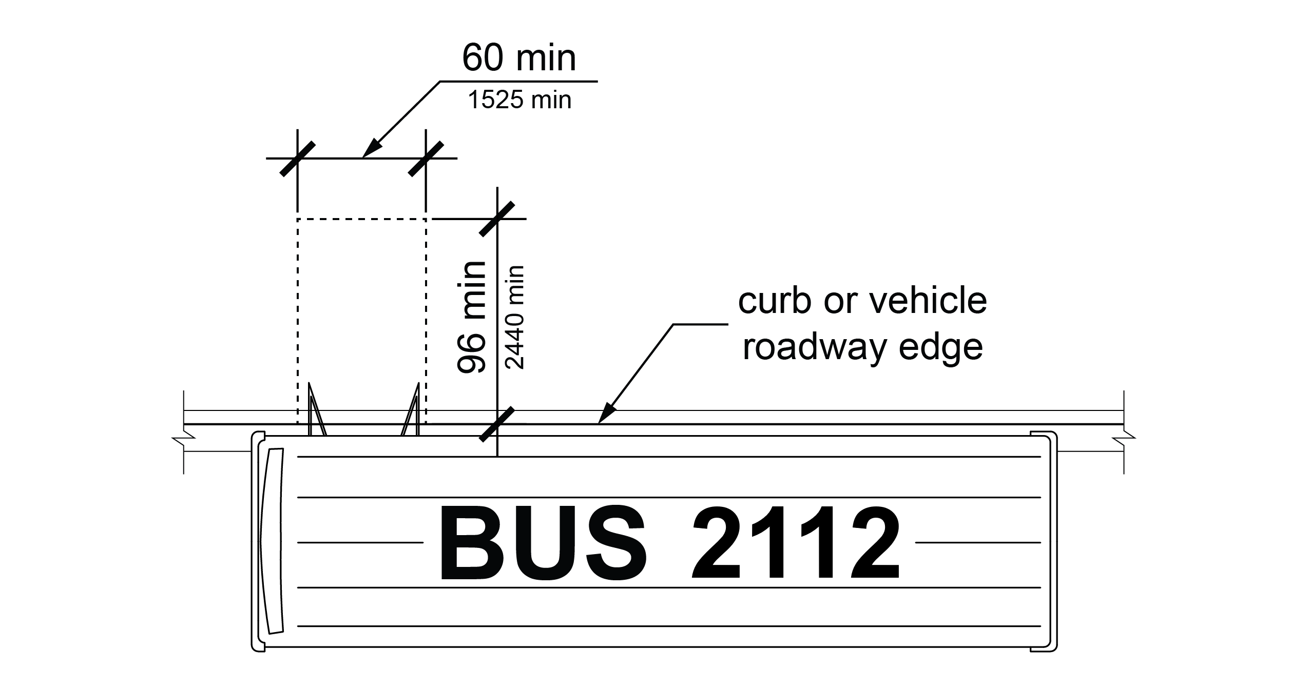
Boarding and alighting areas shall have a clear length of 96 inches (2440 mm) minimum, measured perpendicular to the face of the curb or street edge, and a clear width of 60 inches (1525 mm) minimum, measured parallel to the street.
R309.1.1.2 Slope
The slope of boarding and alighting areas measured parallel to the street shall be the same as the grade of the street. The slope of boarding and alighting areas measured perpendicular to the street shall be 1:48 (2.1%) maximum.
R309.1.2 Boarding Platforms
Boarding platforms at transit stops shall comply with R309.1.2 and R309.1.3.
R309.1.2.1 Platform and Vehicle Floor Coordination
Boarding platforms shall be positioned to coordinate with vehicles in accordance with the applicable requirements in 49 CFR parts 37 and 38.
R309.1.2.2 Slope
The slope of the boarding platform measured parallel to the track or street shall be the same as the grade of the track or street. The slope of the boarding platform measured perpendicular to the track or street shall be 1:48 (2.1%) maximum.
R309.1.3 Common Requirements
Boarding and alighting areas and boarding platforms shall comply with R309.1.3.
R309.1.3.1 Surfaces
The surfaces of boarding and alighting areas and boarding platforms shall comply with R302.6.
R309.1.3.2 Connection to Existing Pedestrian Circulation Paths
In alterations, boarding and alighting areas and boarding platforms shall be connected to existing pedestrian circulation paths by pedestrian access routes complying with R302.
R309.2 Transit Shelters
Transit shelters shall comply with R309.2.
R309.2.1 Connection to Boarding and Alighting Areas
Transit shelters shall be connected by pedestrian access routes complying with R302 to boarding and alighting areas complying with R309.1.1 or boarding platforms complying with R309.1.2.
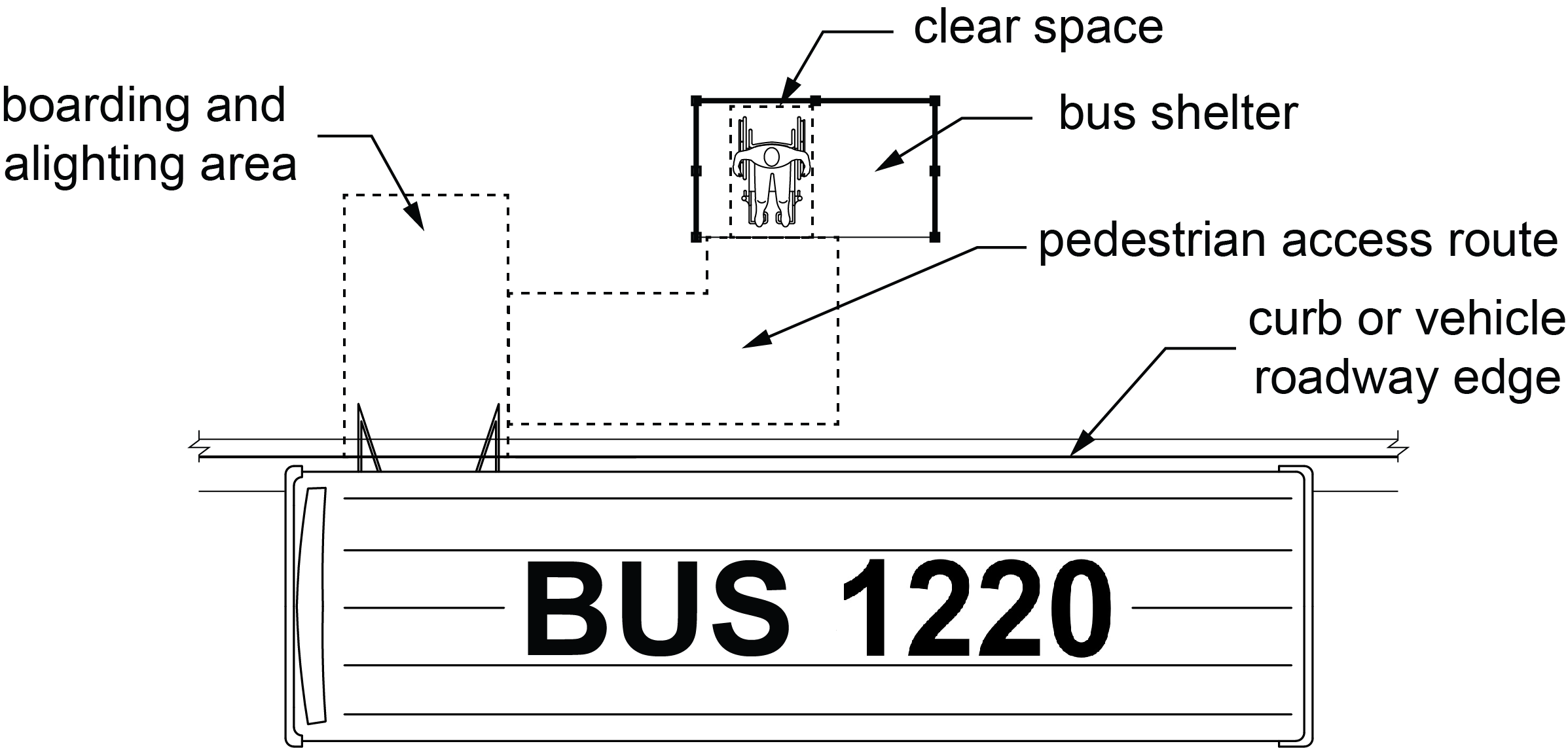
R309.2.2 Clear Space
Transit shelters shall provide a minimum clear space complying with R404 entirely within the shelter. Where seating is provided within transit shelters, the clear space shall be located either at one end of a seat or so as to not overlap the area within 18 inches (455 mm) from the front edge of the seat.
R309.2.3 Environmental Controls
Where provided, environmental controls within transit shelters shall be proximity-actuated.
R309.2.4 Protruding Objects
Protruding objects within transit shelters shall comply with R402.
R310 On-Street Parking Spaces
R310.1 General
On-street parking spaces shall comply with R310.
R310.2 Parallel On-Street Parking Spaces
Parallel on-street parking spaces shall comply with R310.2.
R310.2.1 Dimensions
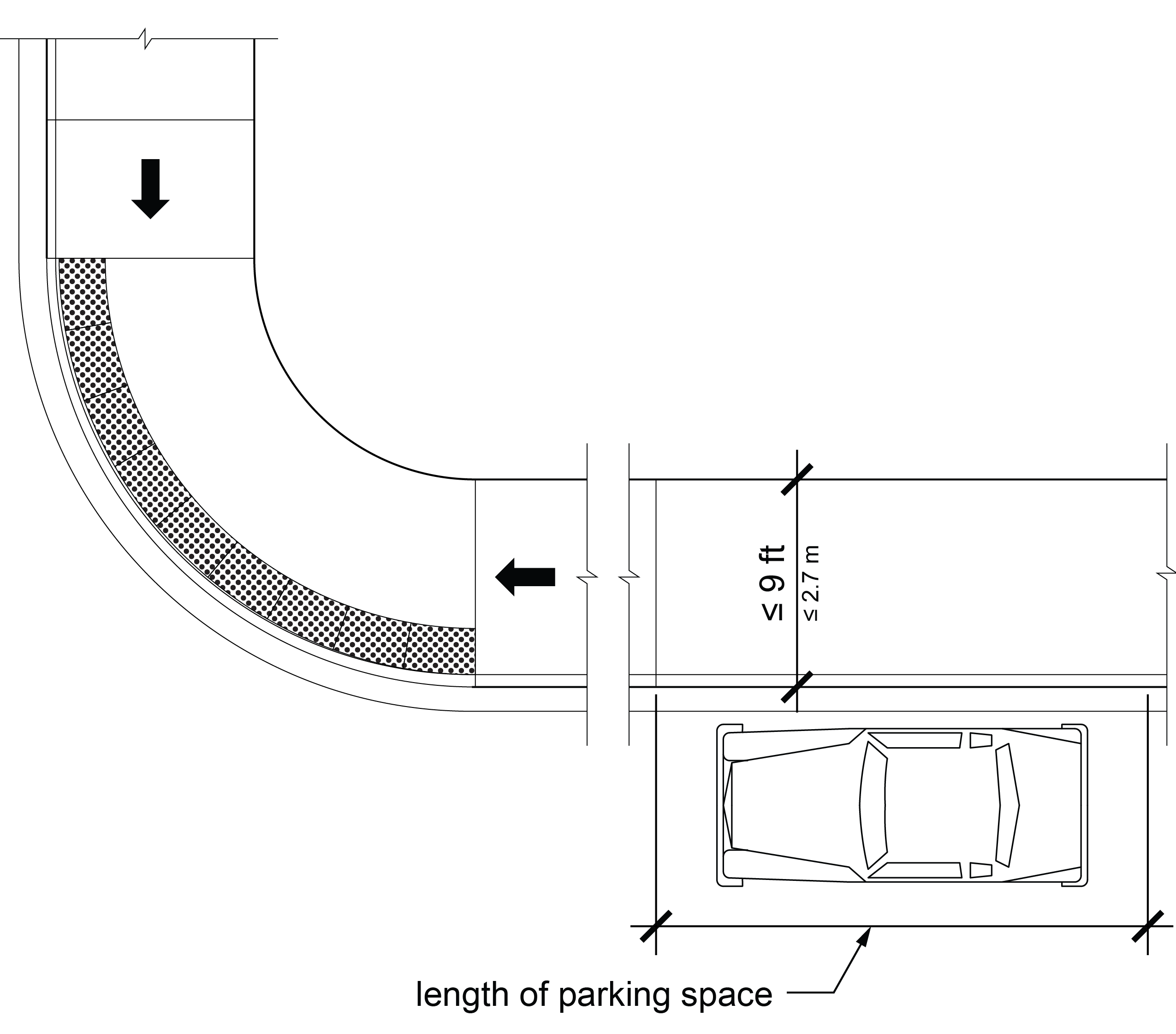
Parallel on-street parking spaces shall be 24 feet (7.3 m) long minimum and 13 feet (4.0 m) wide minimum. Parallel on-street parking spaces shall not encroach on the traveled way.
EXCEPTIONS: 1. Where parallel on-street parking spaces are altered but the adjacent pedestrian circulation path is not, any accessible parallel on-street parking spaces provided may have the same dimensions as the adjacent parallel on-street parking spaces if they are provided nearest the crosswalk at the end of the block face or nearest a midblock crosswalk, and a curb ramp or blended transition is provided serving the crosswalk.
2. In alterations, where providing parallel on-street parking spaces with the dimensions specified in R310.2.1 would result in an available right-of-way width less than or equal to 9 feet (2.7 m), measured from the curb line to the right-of-way line, the accessible parallel on-street parking spaces may have the same dimensions as the adjacent parallel on-street parking spaces if they are provided nearest the crosswalk at the end of the block face or nearest a midblock crosswalk, and a curb ramp or blended transition is provided serving the crosswalk.
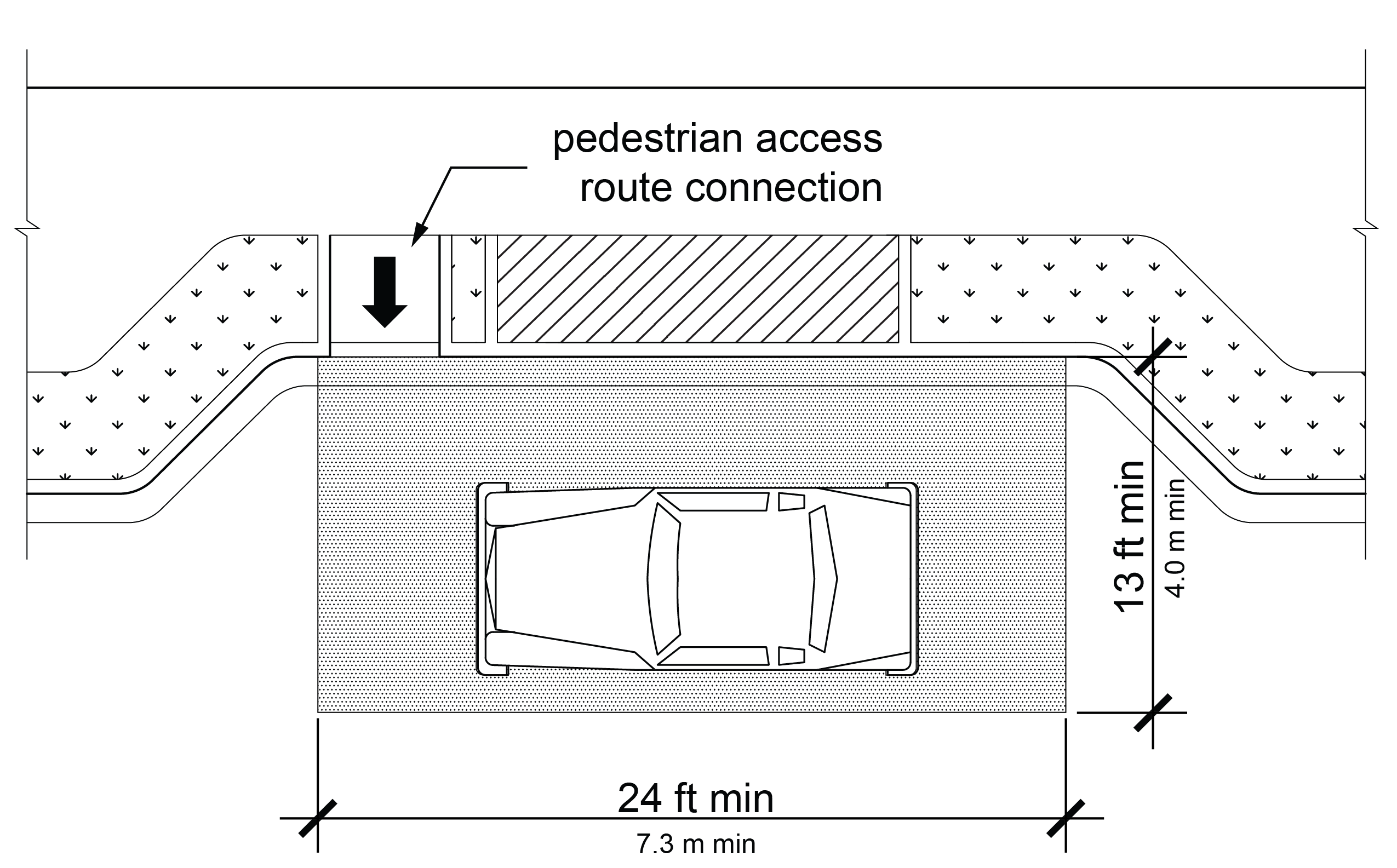
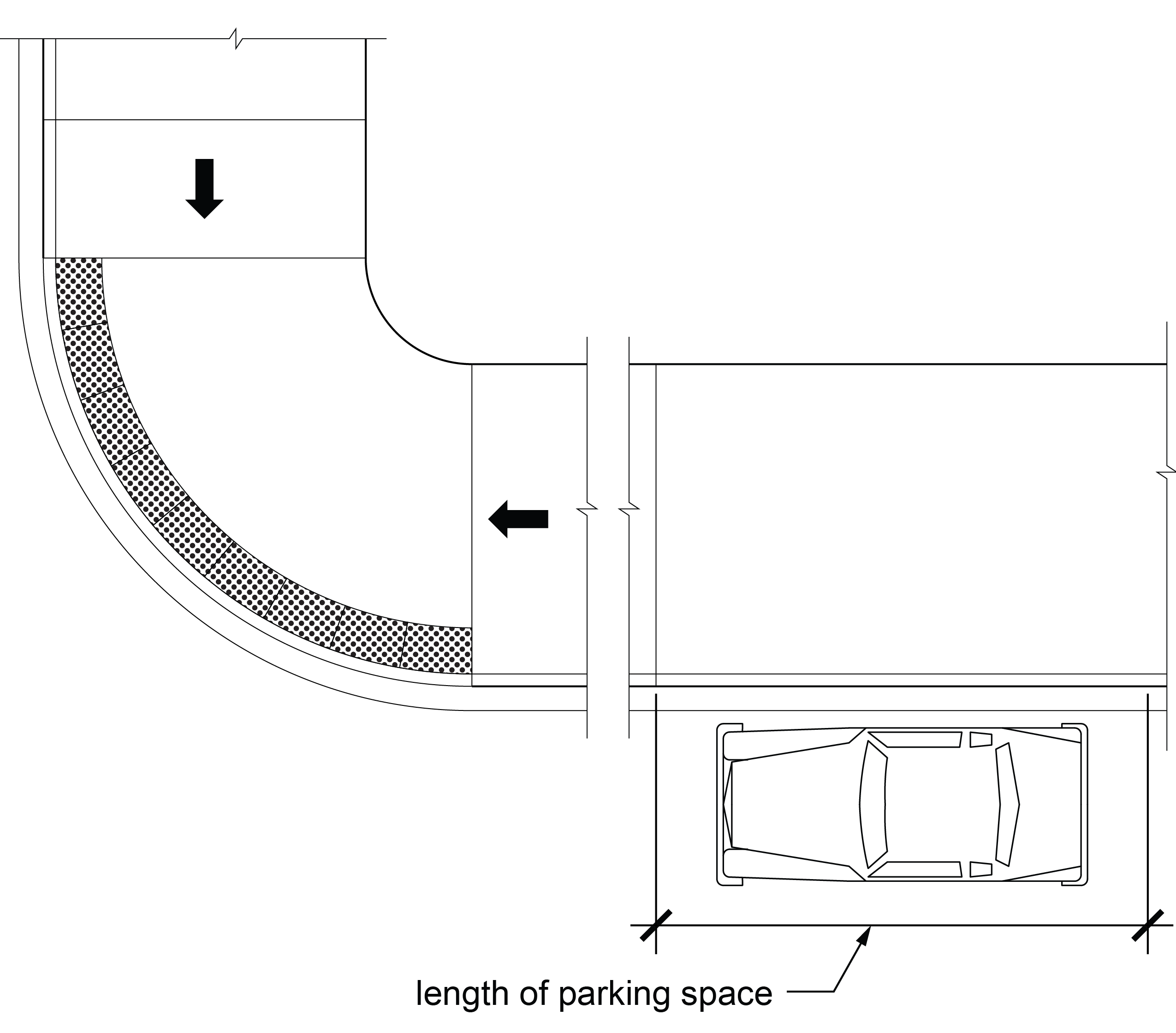
R310.2.2 Pedestrian Access Route Connection
Parallel on-street parking spaces shall connect to pedestrian access routes. Where curb ramps and blended transitions are used, they shall not reduce the required width or length of the parking spaces and shall be located at either end of the parking space. Where two or more accessible parallel on-street parking spaces complying with the dimensions specified in R310.2.1 are contiguous on a block face, each accessible parallel on-street parking space shall have an independent connection to the pedestrian access route. Curb ramps and blended transitions shall be provided in accordance with R203.6.1.3 and shall comply with R304. Detectable warning surfaces are not required on curb ramps and blended transitions used exclusively to connect accessible on-street parallel parking spaces to pedestrian access routes.
EXCEPTION: In alterations, where parallel on-street parking spaces are provided in accordance with Exception 1 or 2 to R310.2.1, the parallel on-street parking space shall be connected to the curb ramp or blended transition serving the crosswalk by a pedestrian circulation path complying with R302.6, except that changes in level are not permitted.
R310.2.3 Surfaces
Surfaces of parking spaces shall comply with R302.6, except that changes in level are not permitted.
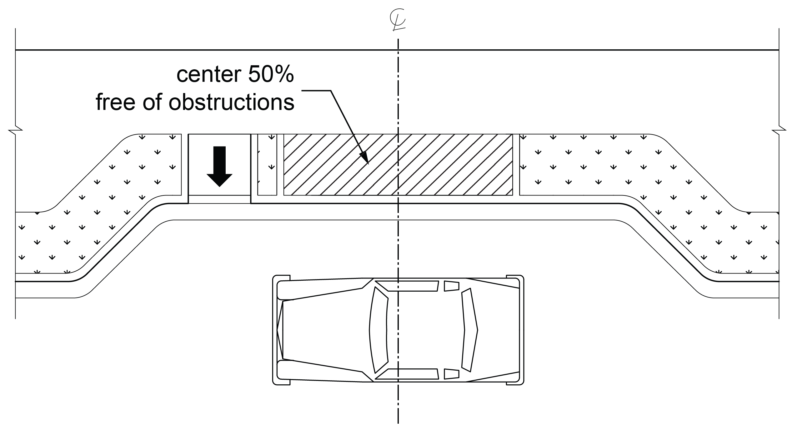
R310.2.4 Clearance Adjacent to Parking Spaces
The center 50 percent of the length of the sidewalk, or other surface, adjacent to an accessible parallel parking space shall be free of obstructions, including parking identification signs, parking pay meters, and parking pay stations, and shall comply with R302.6.
R310.2.5 Identification
Parallel on-street parking spaces shall be identified by signs displaying the International Symbol of Accessibility complying with R411. Signs shall be 60 inches (1525 mm) minimum above the ground surface measured to the bottom of the sign.
R310.3 Perpendicular Parking Spaces
Perpendicular parking spaces shall comply with R310.3.
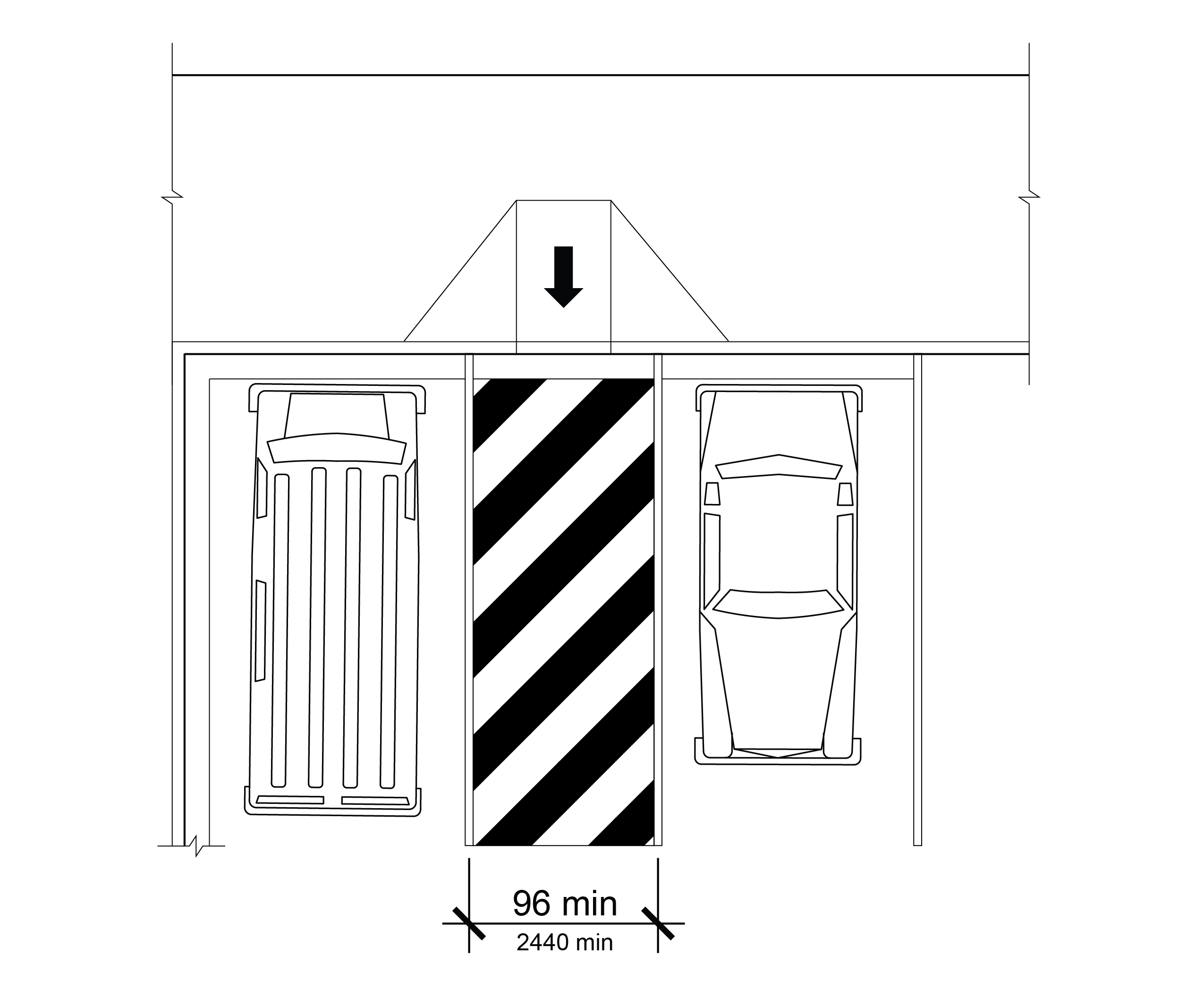
R310.3.1 Access Aisles
Perpendicular on-street parking spaces shall have adjacent access aisles 96 inches (2440 mm) wide minimum extending the full length of the parking space. One access aisle shall be permitted to serve two parking spaces where front and rear entry parking are both permitted. Where an access aisle serves only one parking space and parking is restricted to either front entry or rear entry orientation, the access aisle shall be located on the passenger side of the vehicle.
R310.4 Angled Parking Spaces
Accessible angled parking spaces shall comply with R310.4.
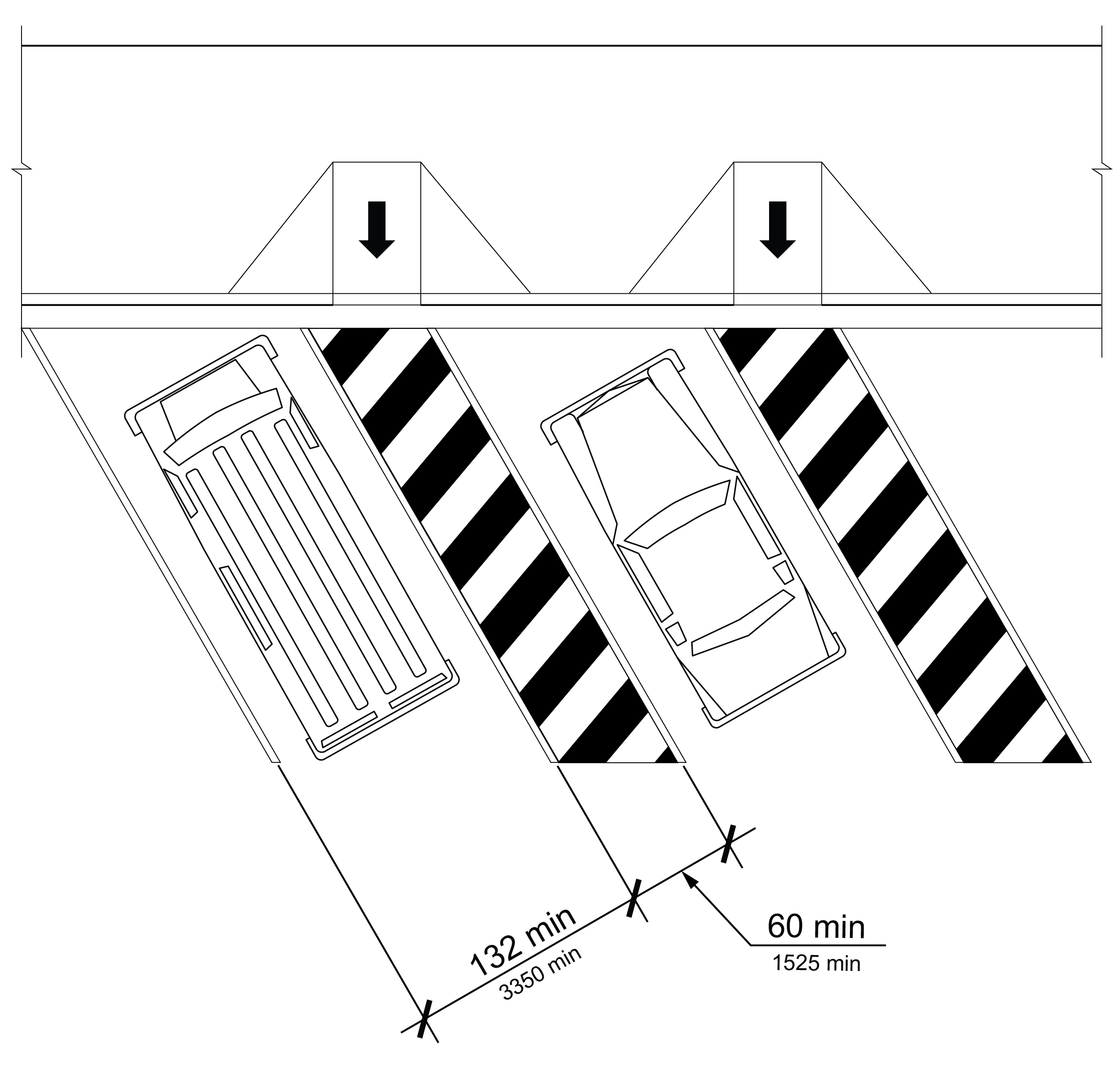
R310.4.1 Width
The width of an angled parking space shall be 132 inches (3350 mm).
R310.4.2 Access Aisles
Each angled on-street parking space shall have an adjacent access aisle 60 inches (1525 mm) wide minimum extending the full length of the parking space on the passenger side.
R310.5 Common Requirements for Perpendicular and Angled Parking Spaces
Perpendicular and angled parking spaces shall comply with R310.5
R310.5.1 Access Aisle Markings
The access aisle surface shall be marked to discourage parking in the access aisle.
R310.5.2 Access Aisle Location
Access aisles shall be located at the same level as the parking space they serve and shall not encroach on the traveled way.
R310.5.3 Pedestrian Access Route Connection
Access aisles shall connect to pedestrian access routes. Where curb ramps and blended transitions are used, they shall not reduce the required width or length of access aisles and parking spaces. Curb ramps and blended transitions shall be provided in accordance with R203.6.1.4 and shall comply with R304. A detectable warning surface is not required on a curb ramp or blended transition used exclusively to connect on-street parking access aisles to pedestrian access routes.
EXCEPTION: In alterations, the access aisle may connect to an existing pedestrian circulation path in accordance with R202.2.
R310.5.4 Surfaces
Surfaces of parking spaces and access aisles serving them shall comply with R302.6, except that changes in level are not permitted.
R310.5.5 Identification
Perpendicular or angled on-street parking spaces shall be identified by signs displaying the International Symbol of Accessibility complying with R411. The signs shall be located at the head of the parking space. Signs shall be 60 inches (1525 mm) minimum above the ground surface measured to the bottom of the sign.
R310.6 Parking Meters and Parking Pay Stations
Parking meters and parking pay stations that serve accessible parking spaces shall provide operable parts complying with R403. The clear space required by R403.2 shall be located so that displays and information on parking meters and pay stations are visible from a point located 40 inches (1015 mm) maximum above the center of the clear space in front of the parking meter or parking pay station.
R311 Passenger Loading Zones
R311.1 General
Accessible passenger loading zones shall comply with R311.
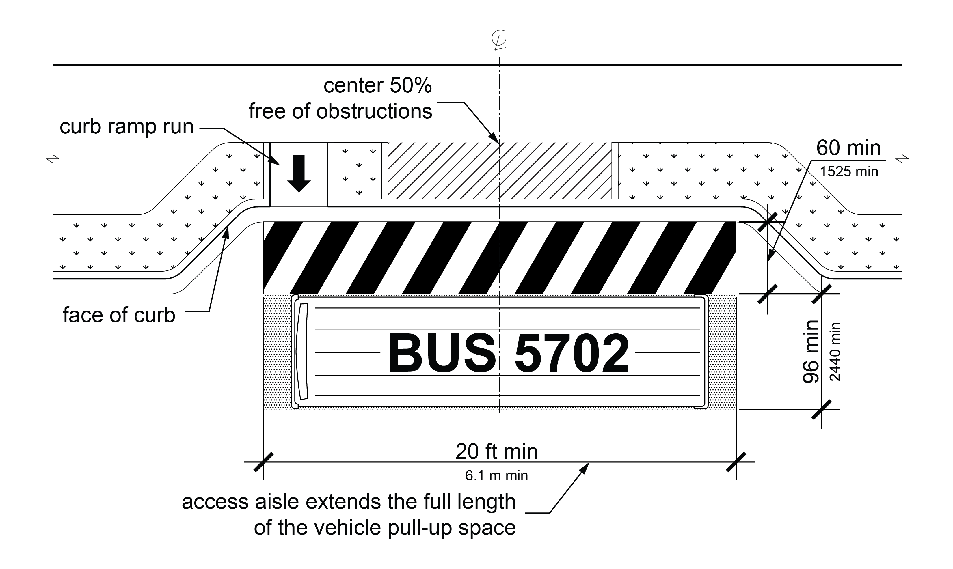
R311.2 Vehicle Pull-Up Space
Accessible passenger loading zones shall provide a vehicular pull-up space that is 96 inches (2440 mm) wide minimum and 20 feet (6.1 m) long minimum.
R311.3 Access Aisle
Vehicle pull-up spaces shall have adjacent access aisles complying with R311.3 that are 60 inches (1525 mm) wide minimum extending the full length of the vehicle pull-up space. Access aisles shall be at the same level as the vehicle pull-up space they serve and shall not encroach on the traveled way.
R311.3.1 Clearance Adjacent to Passenger Loading Zone
The center 50 percent of the length of the sidewalk, or other surface, adjacent to an accessible passenger loading zone shall be free of obstructions and comply with R302.6.
R311.3.2 Marking
Access aisle surfaces shall be marked to discourage parking in them.
R311.4 Surfaces
Surfaces of vehicle pull-up spaces and the access aisles serving them shall comply with R302.6, except that changes in level are not permitted.
R311.5 Pedestrian Access Route Connection
Access aisles shall connect to pedestrian access routes. Where curb ramps and blended transitions are used, they shall be provided in accordance with R203.6.1.4 and comply with R304, and shall not reduce the required width or length of access aisles. Detectable warning surfaces are not required on curb ramps and blended transitions used exclusively to connect access aisles to pedestrian access routes.
EXCEPTION: In alterations, the access aisle may connect to an existing pedestrian circulation path in accordance with R202.2.
Chapter 4: Supplemental Technical Requirements
Advisory: Figures are provided for informational purposes only.
R401 General
R401.1 Scope
The supplemental technical requirements in Chapter 4 shall apply where required by Chapter 2 or where referenced by a requirement in these guidelines.
R402 Protruding Objects and Vertical Clearance
R402.1 General
Protruding objects and vertical clearance shall comply with R402.
R402.2 Protrusion Limits
Objects with leading edges more than 27 inches (685 mm) and less than 80 inches (2030 mm) above the walking surface shall not protrude horizontally more than 4 inches (100 mm) into pedestrian circulation paths.
EXCEPTION: Handrails shall be permitted to protrude 4 ½ inches (115 mm) maximum.
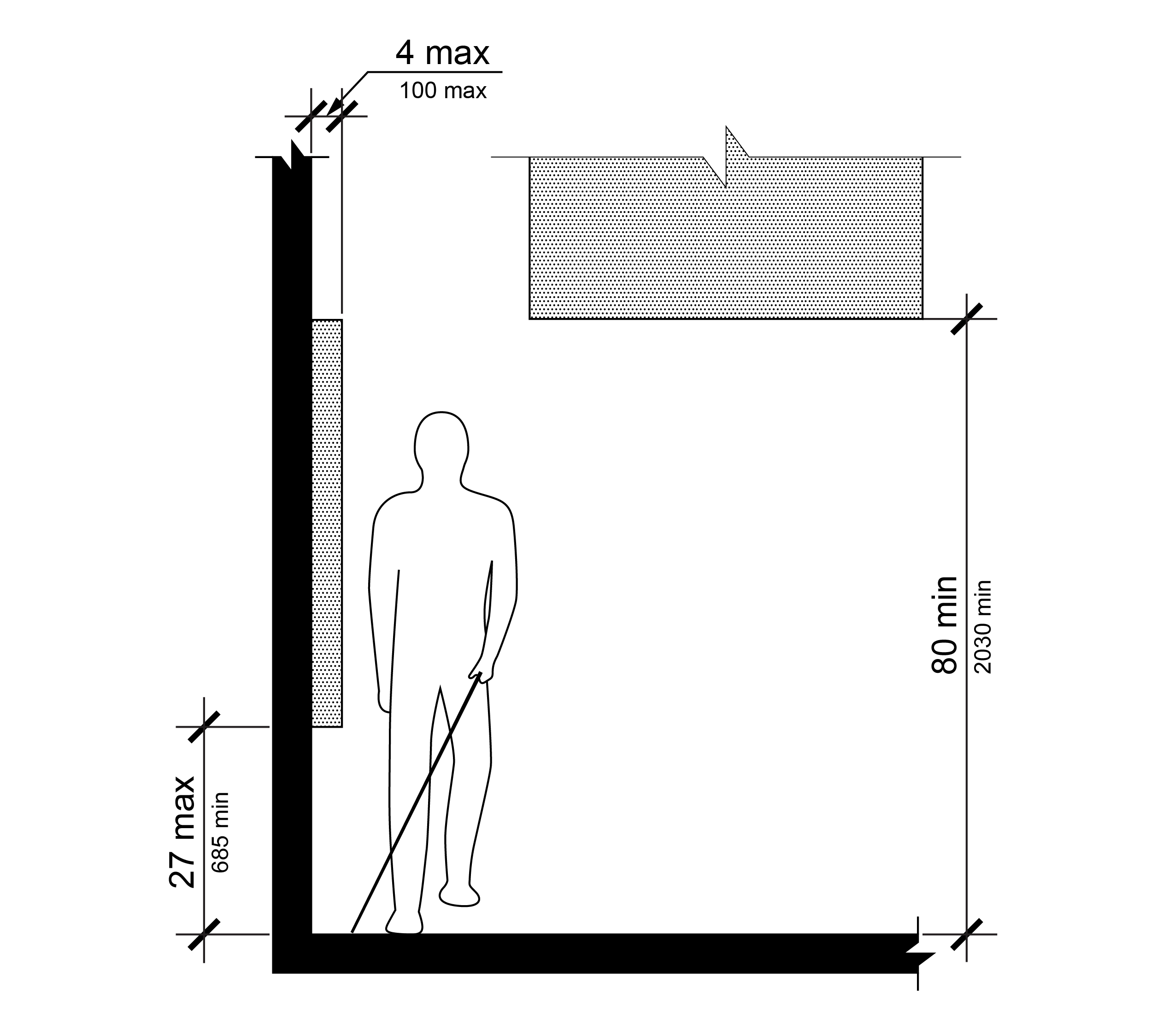
Note: Objects with leading edges more than 27 inches and not more than 80 inches above the walking surface shall not protrude more than 4 inches horizontally into the pedestrian circulation path.
R402.3 Post-Mounted Objects
Where objects are mounted on posts or pylons, they shall comply with R402.3.
EXCEPTION: The sloping portions of handrails serving stairs and ramps shall not be required to comply with R402.3.
R402.3.1 Objects Mounted on Single Post or Pylon
Where objects are mounted on a single post or pylon and the objects are more than 27 inches (685 mm) and less than 80 inches (2030 mm) above the walking surface, the objects shall not protrude into the pedestrian circulation path more than 4 inches (100 mm) measured horizontally from the post or pylon or more than 4 inches (100mm) measured horizontally from the outside edge of the base where the base height is 2 ½ inches (64 mm) minimum.
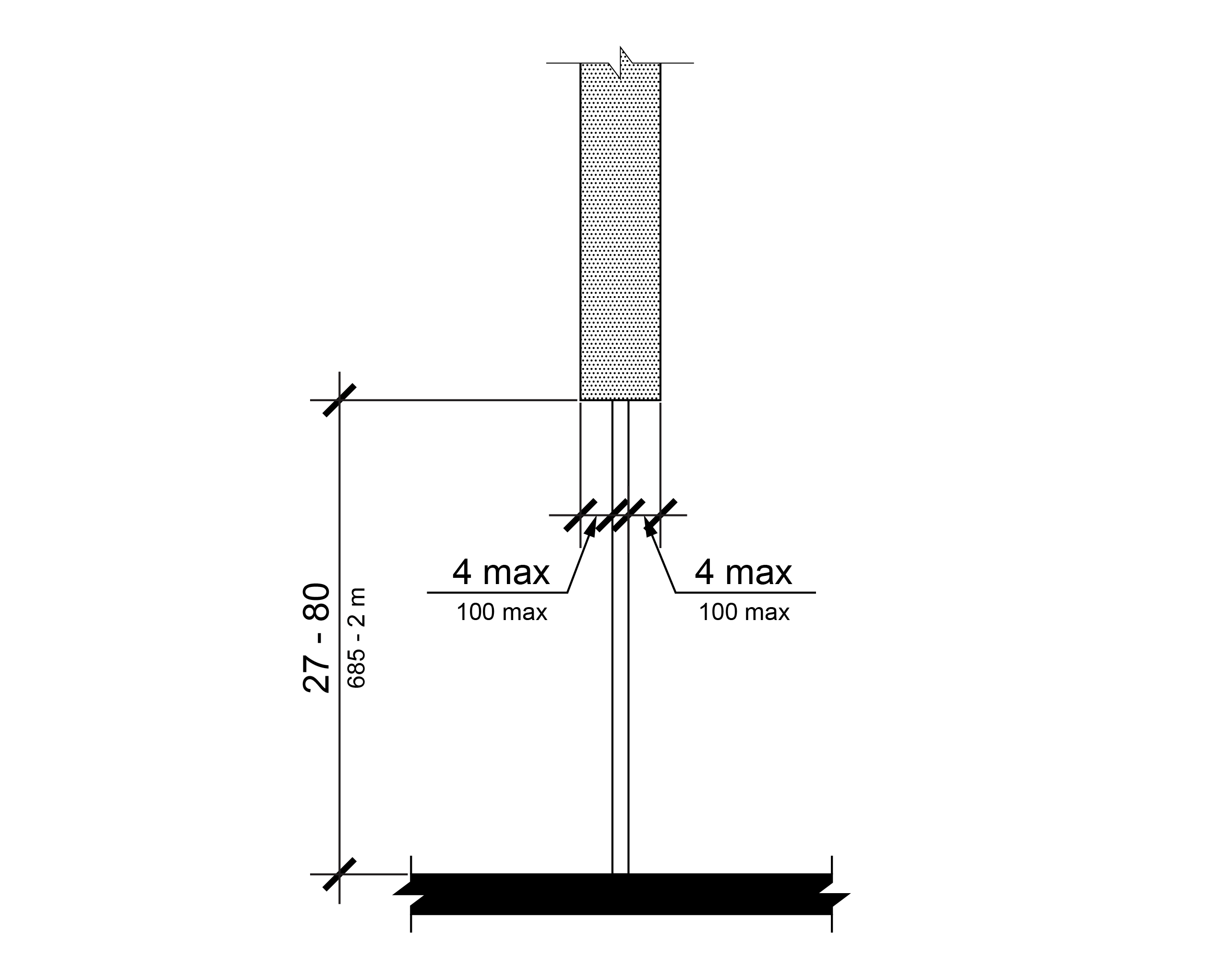
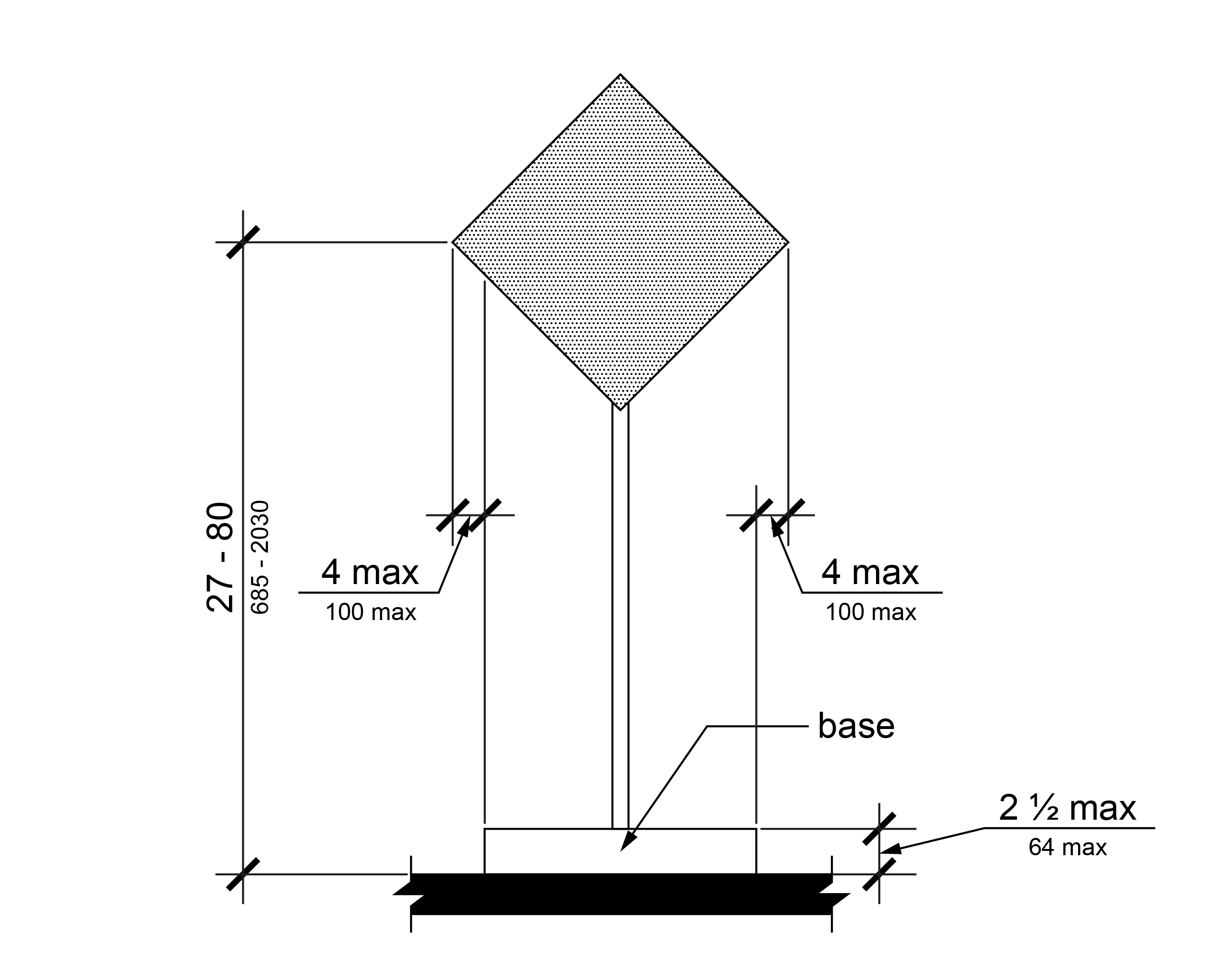
R402.3.2 Objects Mounted Between Posts or Pylons
Where objects are mounted between posts or pylons and the clear distance between the posts or pylons is greater than 12 inches (305 mm), the lowest edge of the object shall be 27 inches (685 mm) maximum or 80 inches (2030 mm) minimum above the walking surface.
EXCEPTION: Objects mounted with the lowest edge greater than 27 inches (685 mm) and less than 80 inches (2030 mm) above the walking surface are permitted if a barrier with its lowest edge at 27 inches (685 mm) maximum above the walking surface is provided between the posts or pylons.
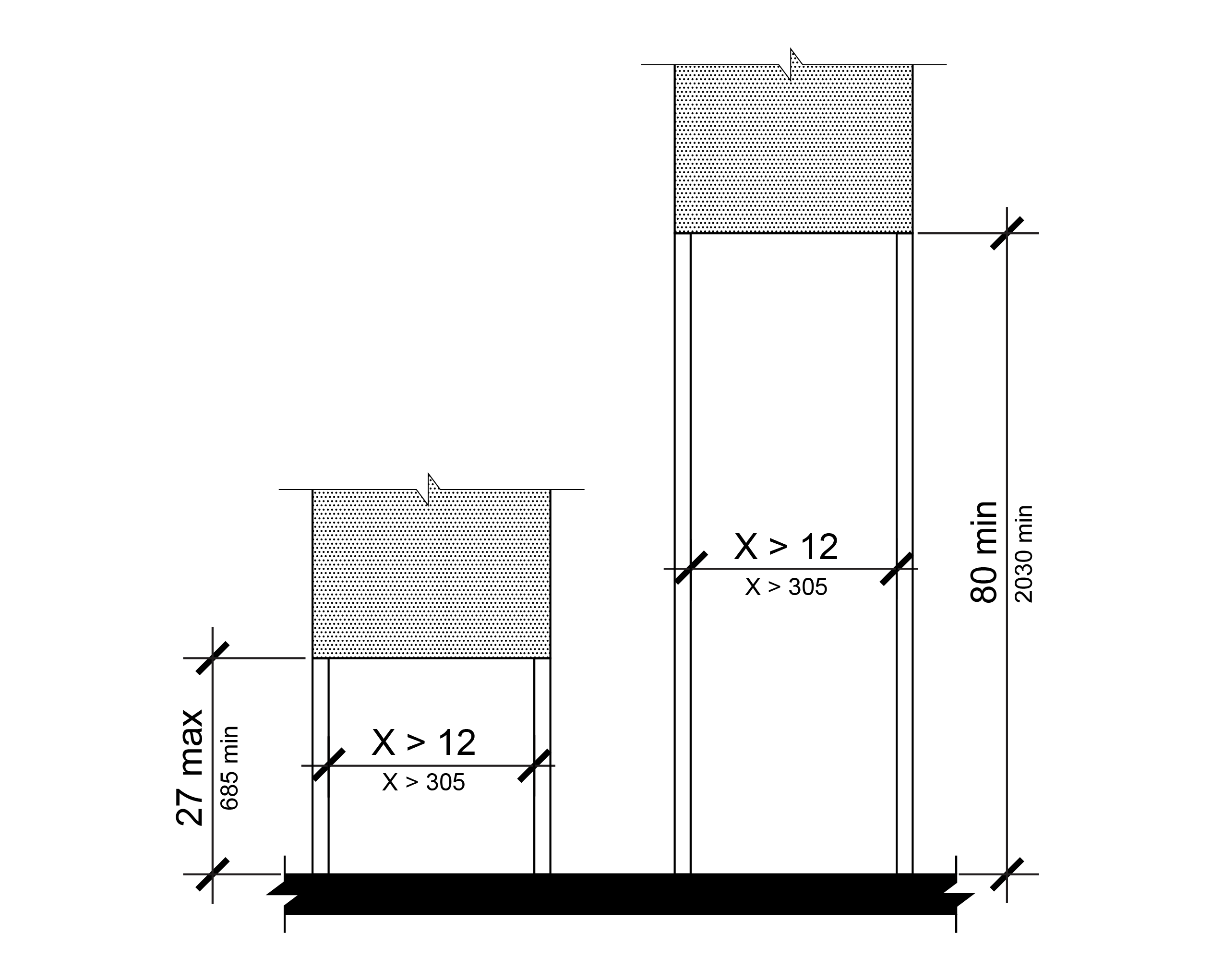
R402.4 Vertical Clearance
Vertical clearance shall be 80 inches (2030 mm) high minimum. Guards or other barriers to prohibit pedestrian travel shall be provided where the vertical clearance is less than 80 inches (2030 mm) high above the walking surface. The lowest edge of the guard or barrier shall be located 27 inches (685 mm) maximum above the walking surface.
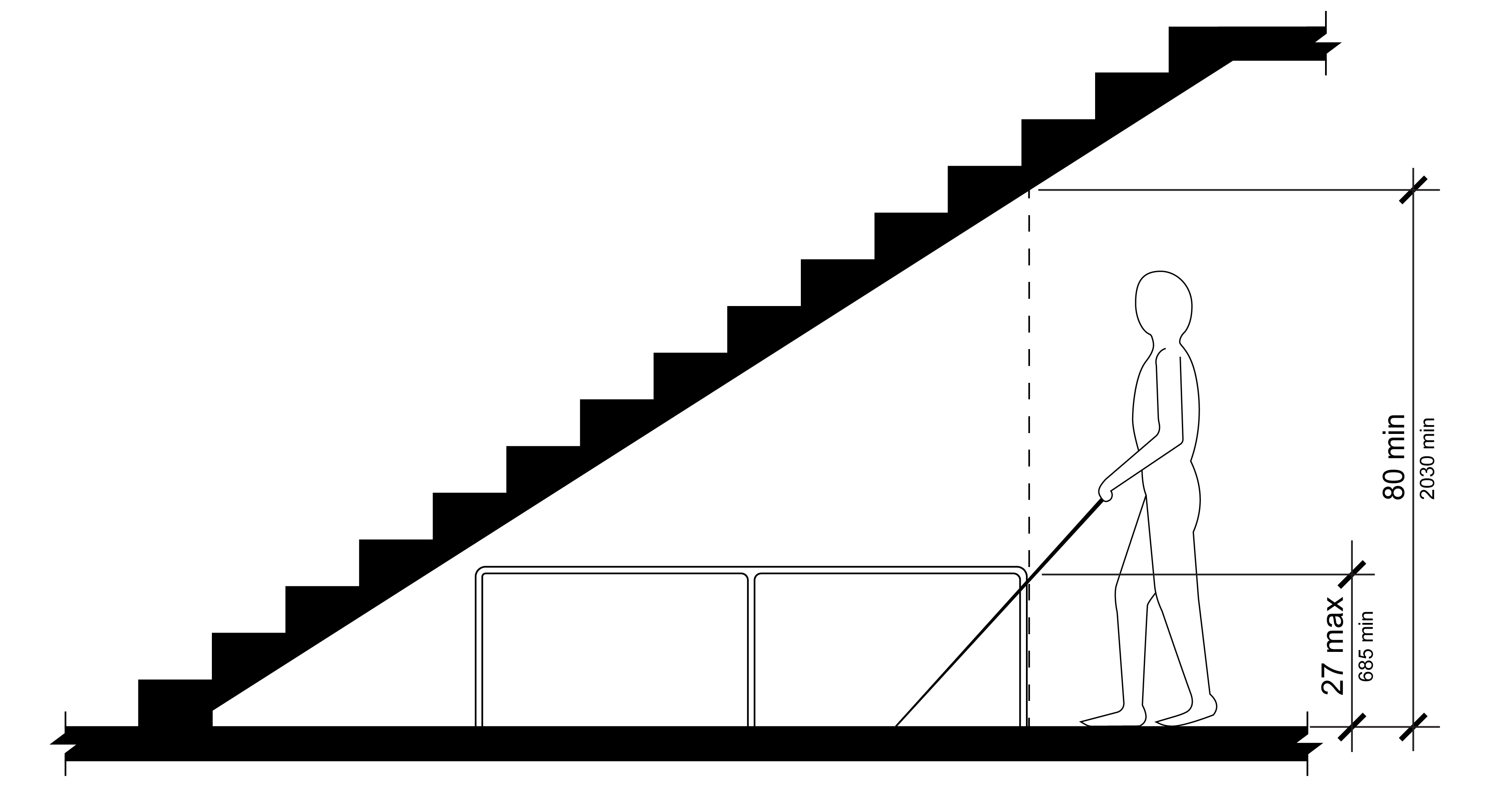
R402.5 Required Clear Width
Protruding objects shall not reduce the clear width required for pedestrian access routes.
R403 Operable Parts
R403.1 General
Operable parts shall comply with R403.
R403.2 Clear Space
A clear space complying with R404 shall be provided at operable parts.
R403.3 Height
Operable parts shall be placed within one or more of the reach ranges specified in R406.
R403.4 Operation
Operable parts shall be operable with one hand and shall not require tight grasping, pinching, or twisting of the wrist. The force required to activate operable parts shall be 5 pounds (22.2 N) maximum.
R404 Clear Spaces
R404.1 General
Clear spaces shall comply with R404.
R404.2 Surfaces
Surfaces of clear spaces shall comply with R302.6. The slope of the clear space shall be 1:48 (2.1%) maximum in both directions.
EXCEPTION: Where the slope of the clear space would exceed 1:48 (2.1%) in either or both directions due to the grade of an adjacent pedestrian access route conforming to the requirements of R302.4, the slope of the clear space may be consistent with the slope of the pedestrian access route.
R404.3 Size
Clear spaces shall be 30 inches (760 mm) minimum by 48 inches (1220 mm) minimum.
R404.4 Knee and Toe Clearance
Unless otherwise specified, clear spaces shall be permitted to include knee and toe clearance complying with R405.
R404.5 Position
Clear spaces shall be positioned either for forward approach where the 30-inch side is nearest to the element, or for parallel approach where the 48-inch side is nearest to the element. Clear spaces shall not be located on curb ramp runs or flares.
R404.6 Approach
One full unobstructed side of a clear space shall adjoin a pedestrian access route or adjoin another clear space.
R404.7 Maneuvering Clearance
Where a clear space is confined on all or part of three sides, additional maneuvering clearance shall be provided in accordance with R404.7.1 and R404.7.2.
R404.7.1 Forward Approach
The clear space and additional maneuvering clearance shall be 36 inches (915 mm) wide minimum where the depth of the confined space exceeds 24 inches (610 mm) measured perpendicular to the element.
R404.7.2 Parallel Approach
The clear space and additional maneuvering clearance shall be 60 inches (1525 mm) wide minimum where the depth of the confined space exceeds 15 inches (380 mm) measured perpendicular to the element.
R405 Knee and Toe Clearance
R405.1 General
Where space beneath an element is included as part of a clear space, the space shall comply with R405. Additional space shall not be prohibited beneath an element but shall not be considered as part of the clear space.
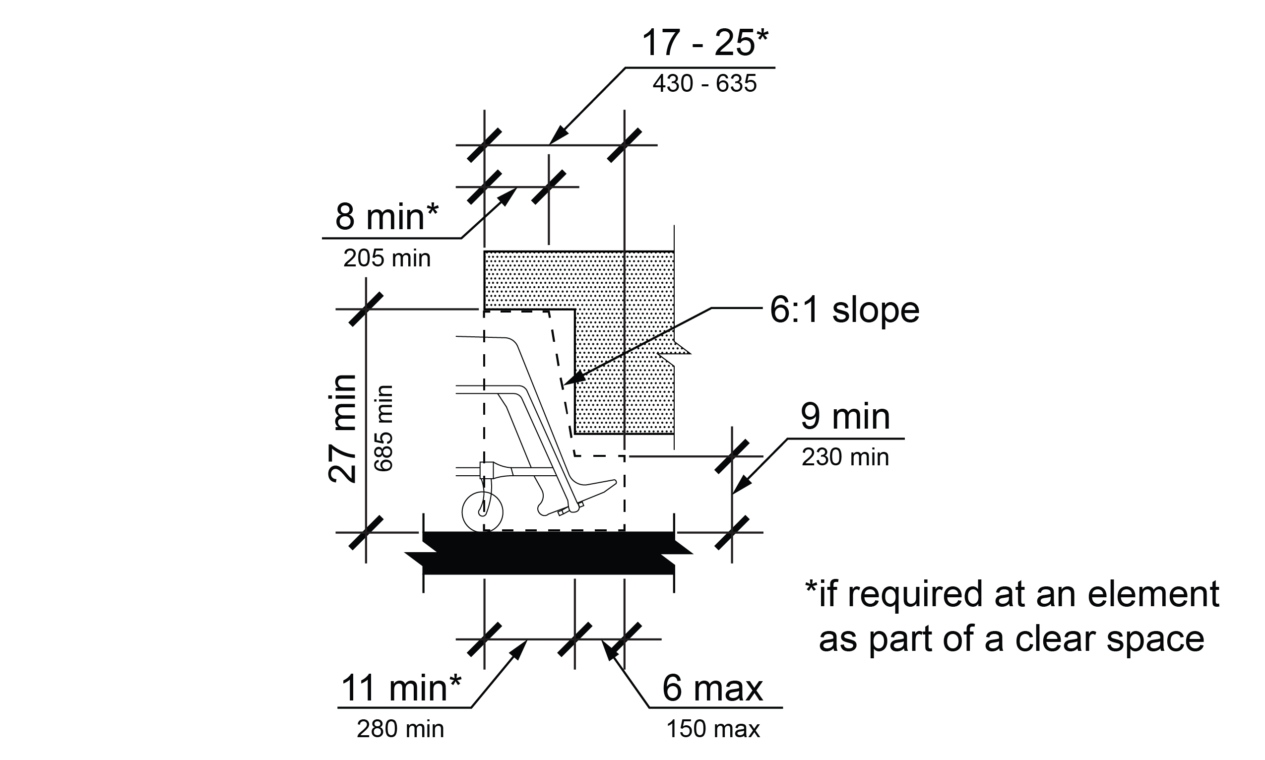
R405.2 Toe Clearance
Toe clearance shall comply with R405.2.
R405.2.1 General
Space under an element between the ground surface and 9 inches (230 mm) above the ground surface shall be considered toe clearance and shall comply with R405.2.
R405.2.2 Maximum Depth
Toe clearance shall extend 25 inches (635 mm) maximum under an element.
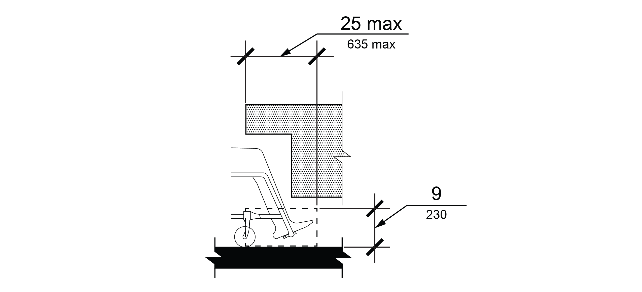
R405.2.3 Minimum Required Depth
Where toe clearance is required at an element as part of a clear space, the toe clearance shall extend 17 inches (430 mm) minimum under the element.
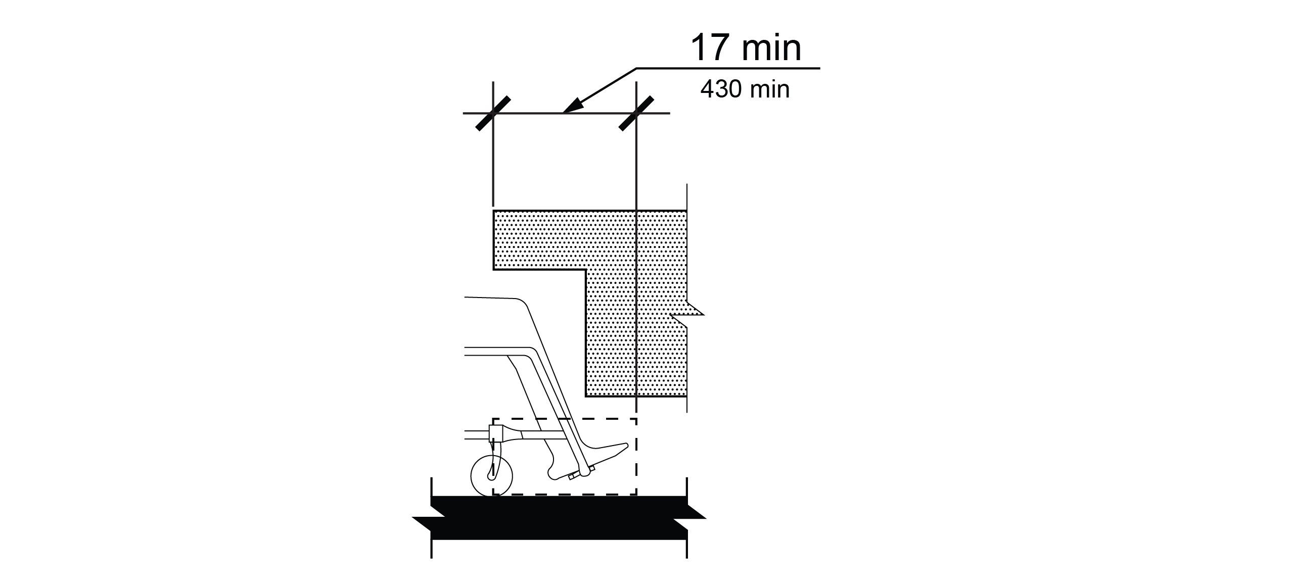
R405.2.4 Additional Clearance
Space extending greater than 6 inches (150 mm) beyond the available knee clearance at 9 inches above the ground surface shall not be considered toe clearance.
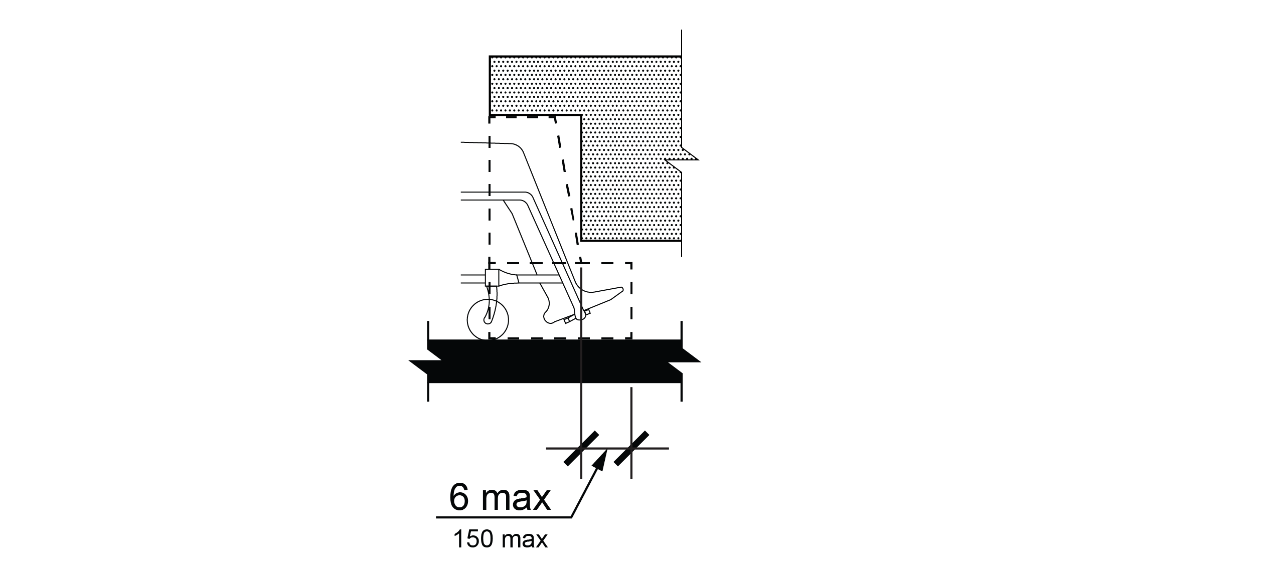
R405.2.5 Width
Toe clearance shall be 30 inches (760 mm) wide minimum.
R405.3 Knee Clearance
Knee clearance shall comply with R405.3.
R405.3.1 General
Space under an element between 9 inches (230 mm) and 27 inches (685 mm) above the ground surface shall be considered knee clearance and shall comply with R405.3.
R405.3.2 Maximum Depth
Knee clearance shall extend 25 inches (635 mm) maximum under an element at 9 inches (230 mm) above the ground surface.
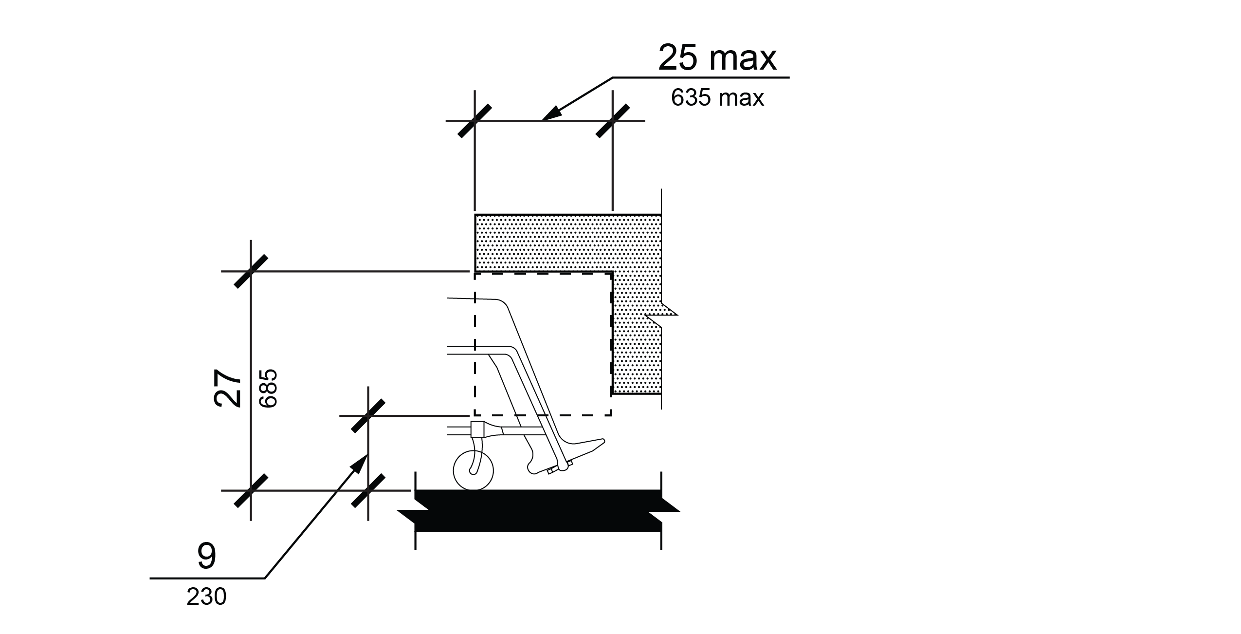
R405.3.3 Minimum Required Depth
Where knee clearance is required under an element as part of a clear space, the knee clearance shall be 11 inches (280 mm) deep minimum at 9 inches (230 mm) above the ground surface, and 8 inches (205 mm) deep minimum at 27 inches (685 mm) above the ground surface.
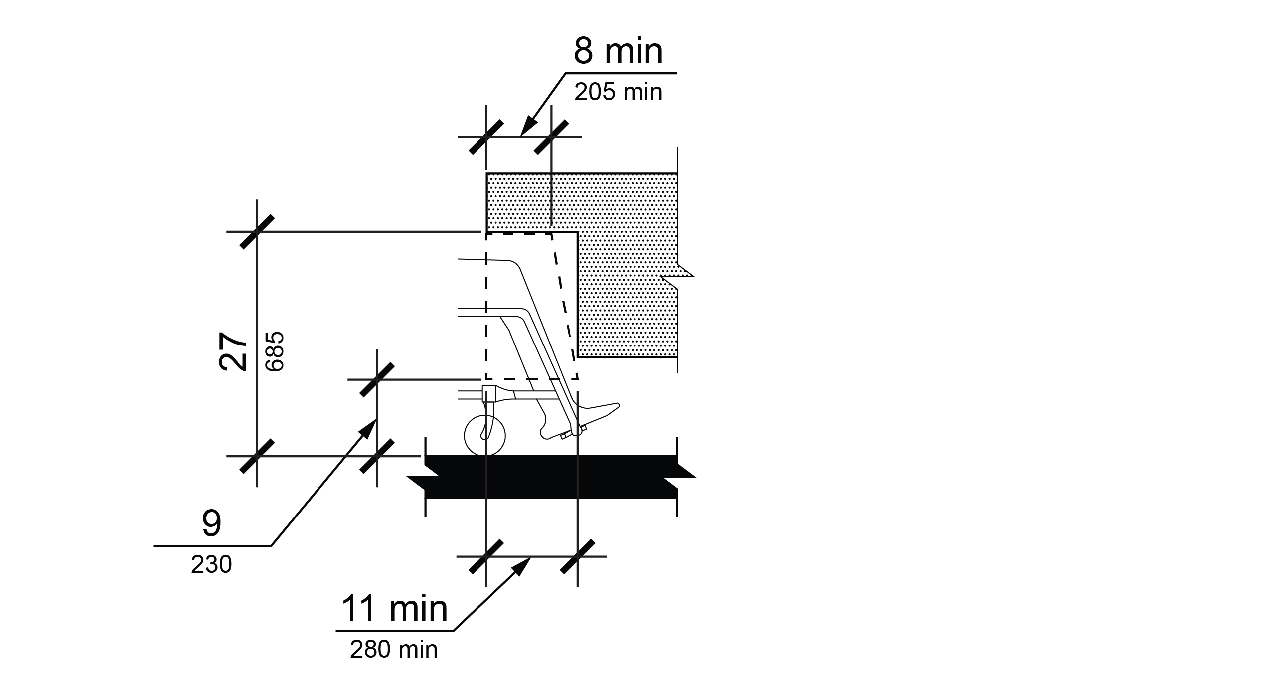
R405.3.4 Clearance Reduction
Between 9 inches (230 mm) and 27 inches (685mm) above the ground surface, the knee clearance shall be permitted to reduce at a rate of 1 inch (25 mm) in depth for each 6 inches (150 mm) in height.
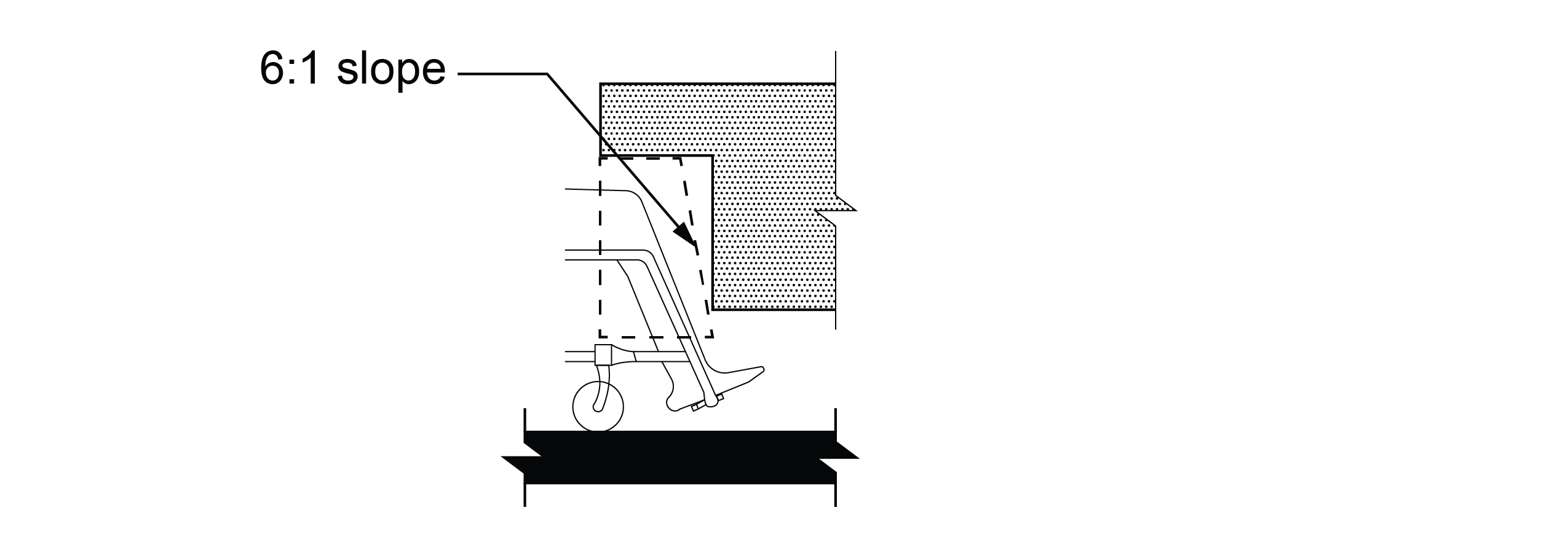
R405.3.5 Width
Knee clearance shall be 30 inches (760 mm) wide minimum.
R406 Reach Ranges
R406.1 General
Reach ranges shall comply with R406.
R406.2 Reach Range Limits
For forward and parallel approaches, the high reach shall be 48 inches (1220 mm) maximum and the low reach shall be 15 inches (380 mm) minimum above the ground surface.
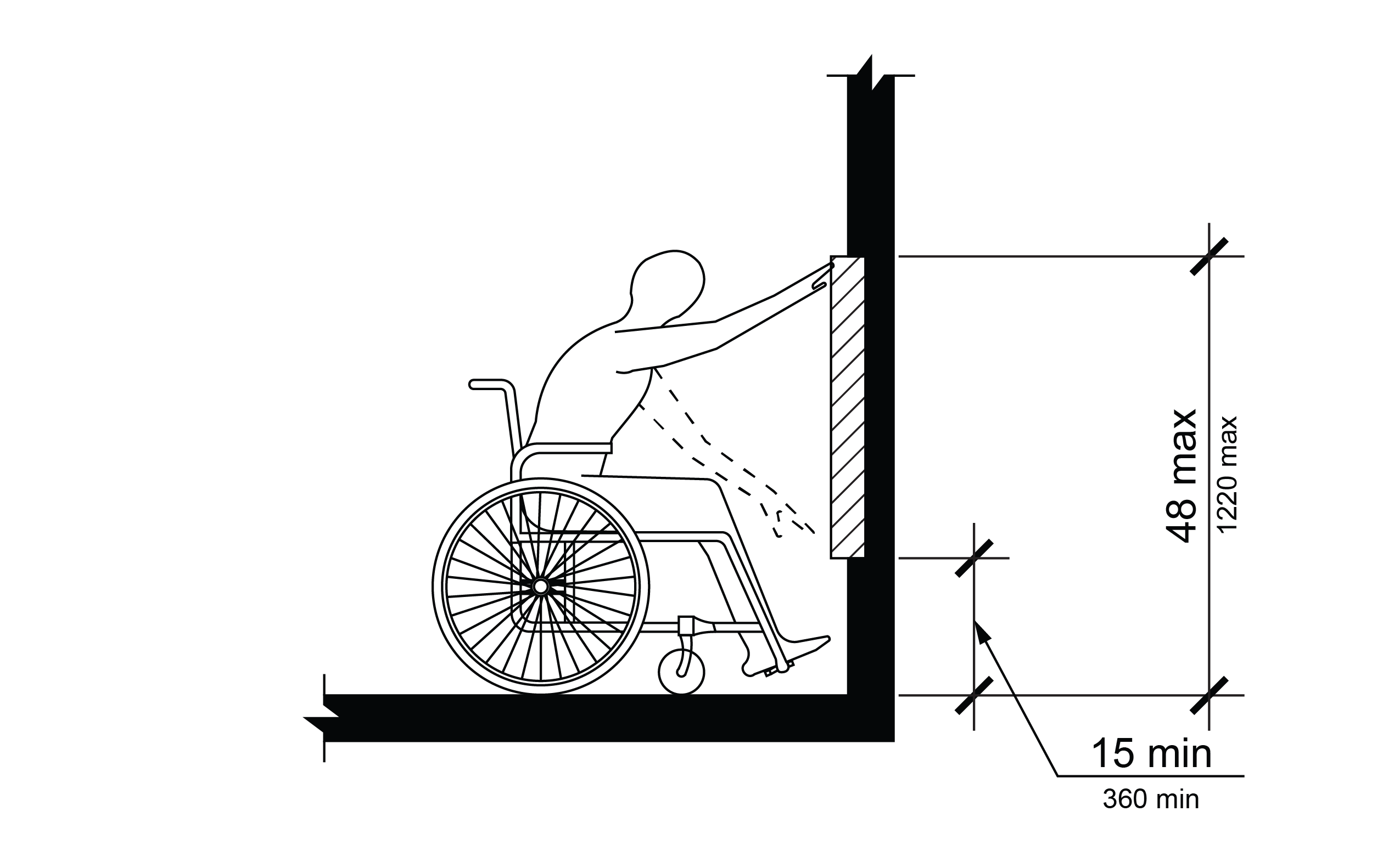
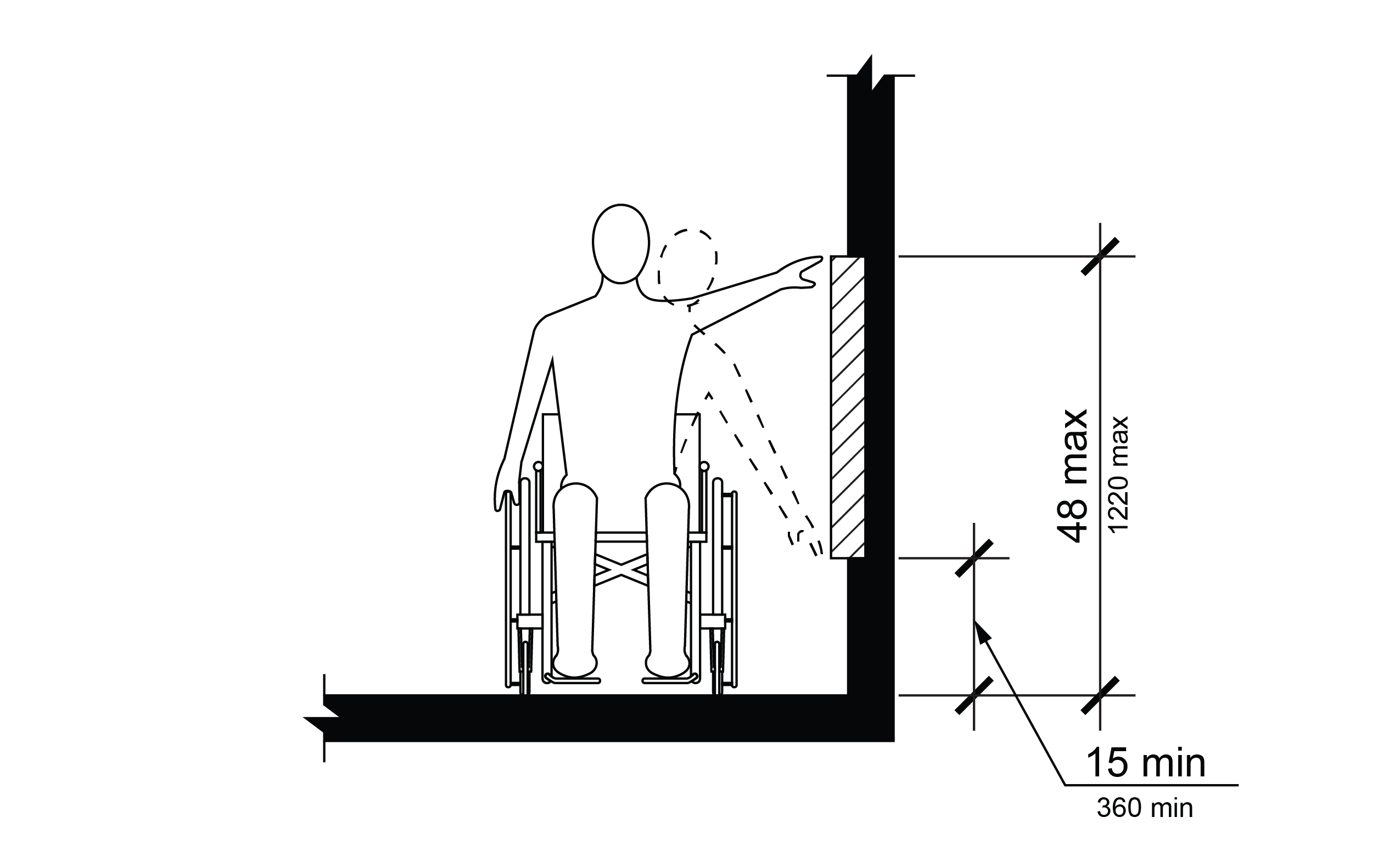
R406.3 Obstructions
Obstructed reach shall comply with R406.3.
R406.3.1 Forward Reach
Where the clear space is configured solely for a forward approach to an element, obstructions shall not be permitted between the clear space and the element for a forward reach.
R406.3.2 Side Reach
Where a clear space is configured for a parallel approach to an element, an obstruction shall be permitted between the clear space and the element where the depth of the obstruction is 10 inches (255 mm) maximum and the height of the obstruction is 34 inches (865 mm) maximum.
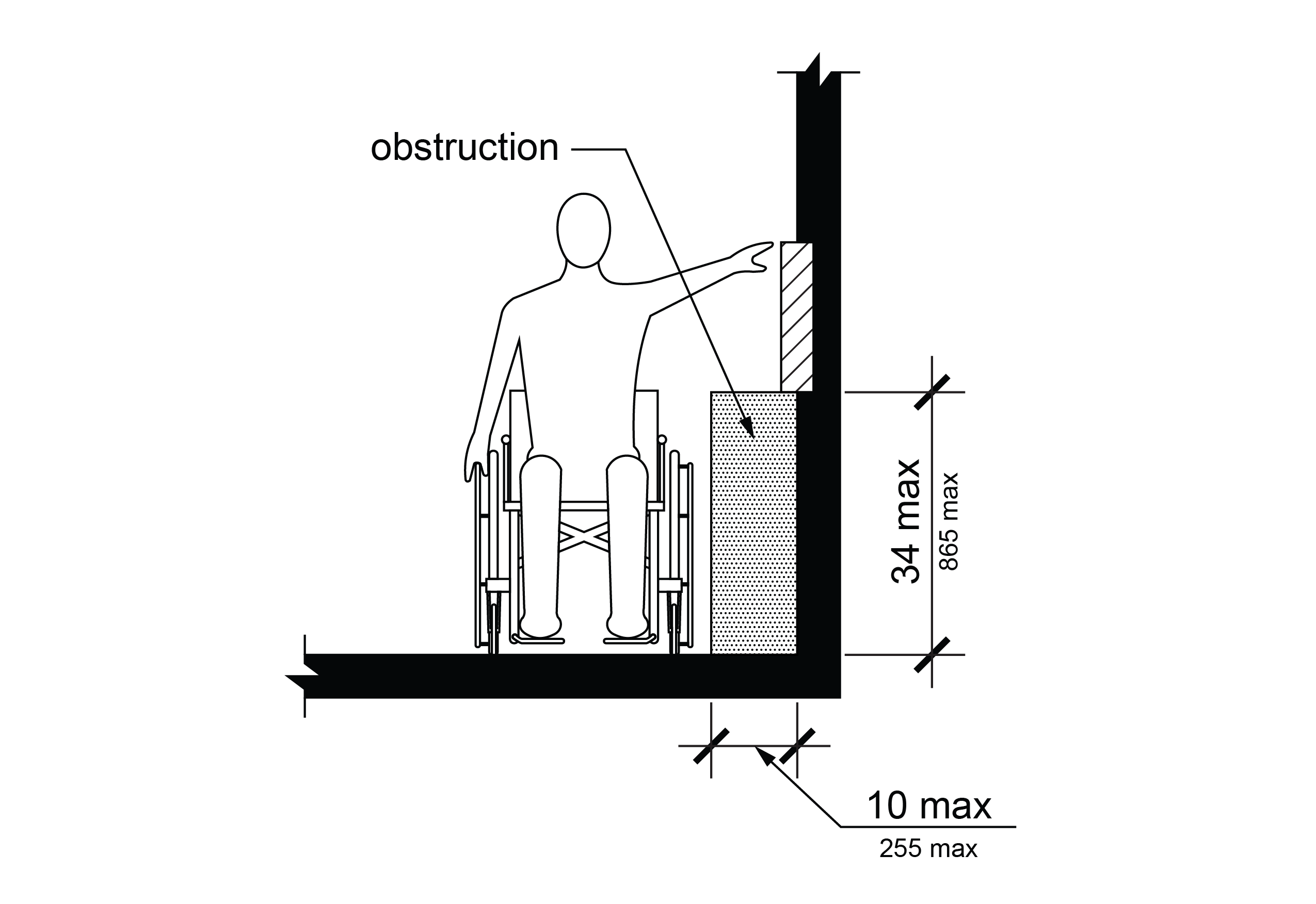
R407 Ramps
R407.1 General
Ramps shall comply with R407. R407 does not apply to curb ramps or pedestrian access routes following the grade established for the adjacent street consistent with the requirements of R302.4.1.
R407.2 Running Slope
The running slope of each ramp run shall be 1:12 (8.3%) maximum.
R407.3 Cross Slope
The cross slope of ramp runs shall be 1:48 (2.1%) maximum.
R407.4 Clear Width
The clear width of a ramp run shall be 48 inches (1220 mm) minimum. Where handrails are provided, the clear width between handrails shall be 48 inches (1220 mm) minimum.
EXCEPTION: Where a ramp only serves a building entrance, the clear width of the ramp run shall be permitted to be 36 inches (915 mm) minimum. Where handrails are provided, the clear width between handrails shall be permitted to be 36 inches (915 mm) minimum.
R407.5 Rise
The rise for any ramp run shall be 30 inches (760 mm) maximum.
R407.6 Landings
Ramps shall have landings at the top and the bottom of each ramp run. Landings shall comply with R407.6.

R407.6.1 Slope
Landing slopes shall be 1:48 (2.1%) maximum parallel and perpendicular to the ramp running slope.
R407.6.2 Width
The landing clear width shall be at least as wide as the widest ramp run leading to the landing.
R407.6.3 Length
The landing clear length shall be 60 inches (1525 mm) long minimum.
R407.6.4 Change in Direction
Ramps that change direction between runs at landings shall have a clear landing 60 inches (1525 mm) minimum by 60 inches (1525 mm) minimum.
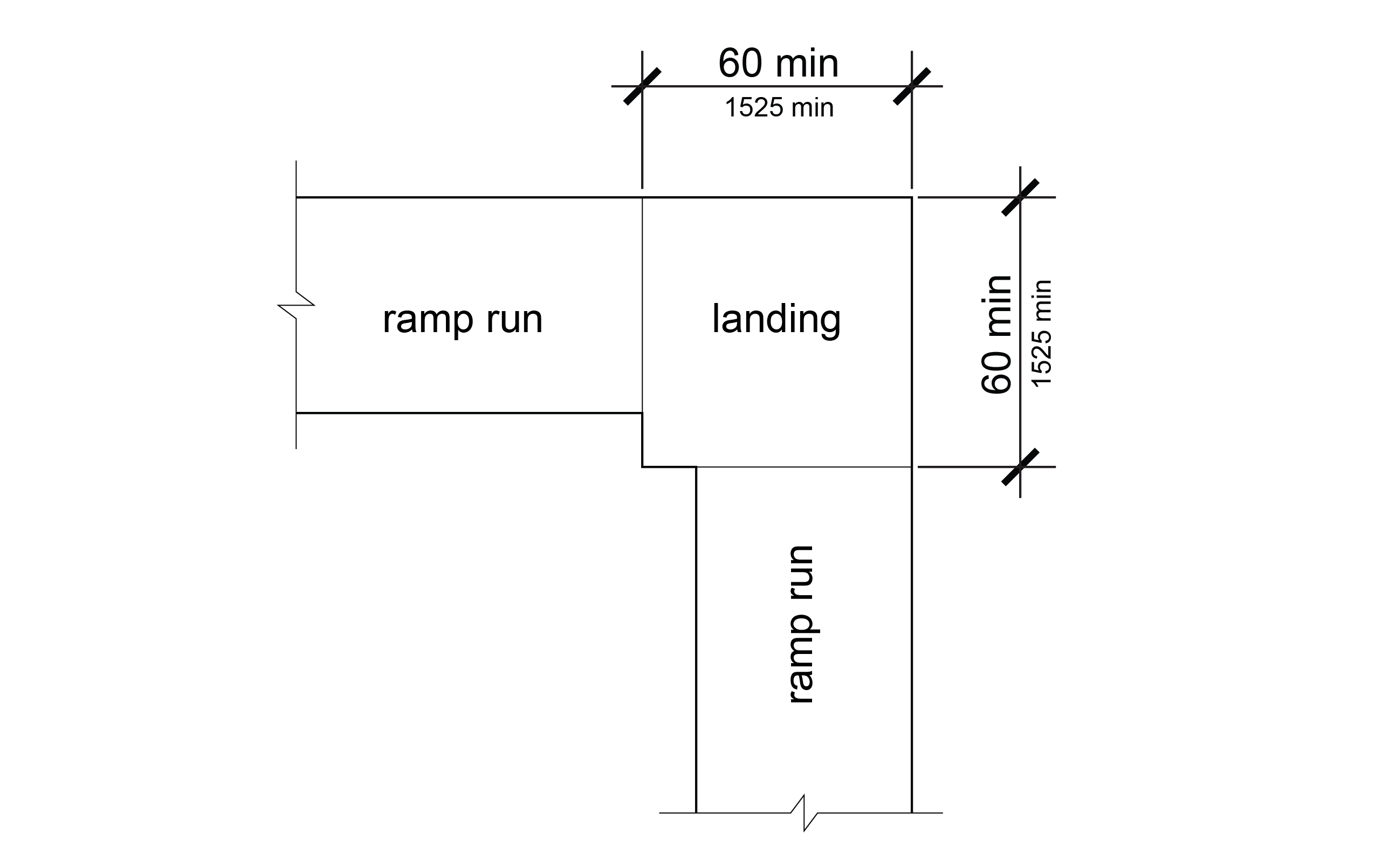
R407.7 Surfaces
Surfaces of ramp runs and landings shall comply with R302.6, except that changes in level are not permitted.
R407.8 Handrails
Ramp runs with a rise greater than 6 inches (150 mm) shall have handrails complying with R409.
R407.9 Edge Protection
Edge protection complying with R407.9.1 or R407.9.2 shall be provided on each side of ramp runs and each side of ramp landings except those serving an adjoining ramp run, stairway, or other pedestrian circulation path.
R407.9.1 Extended Ramp Surface
The surface of the ramp run or landing shall extend 12 inches (305 mm) minimum beyond the inside face of a handrail complying with R409.
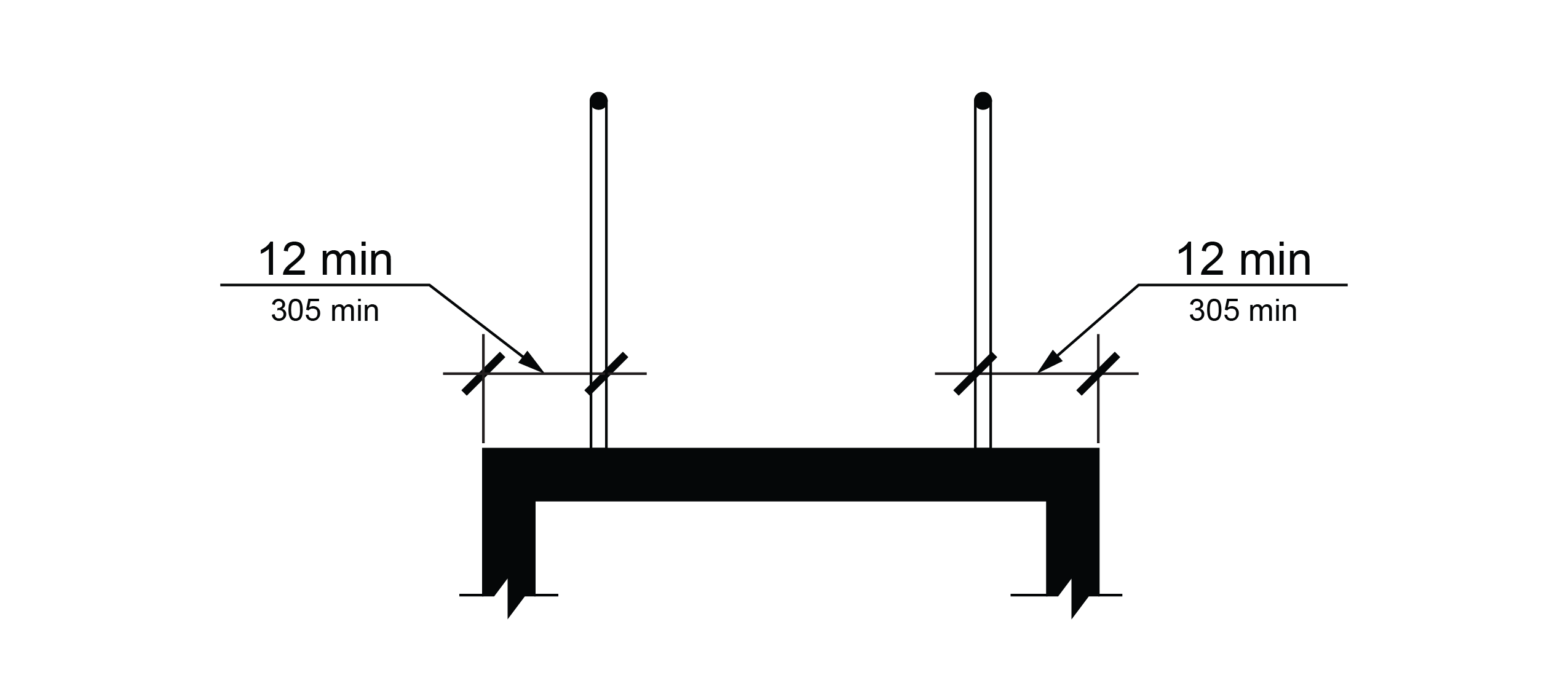
R407.9.2 Curb or Barrier
A curb that is 4 inches (100 mm) high minimum, or a barrier that prevents the passage of a 4-inch (100 mm) diameter sphere, where any portion of the sphere is within 4 inches (100 mm) of the surface of the ramp run or landing, shall be provided.
R408 Stairs
R408.1 General
Stairs shall comply with R408.
R408.2 Treads and Risers
All steps on a flight of stairs shall have uniform riser heights and uniform tread depths. Risers shall be 4 inches (100 mm) high minimum and 7 inches (180 mm) high maximum. Treads shall be 11 inches (280 mm) deep minimum.
R408.3 Open Risers
Open risers are not permitted.
R408.4 Tread Surface
Stair treads shall comply with R302.6, except that changes in level are not permitted.
EXCEPTION: Treads shall be permitted to have a slope not steeper than 1:48 (2.1%).
R408.5 Nosings
The radius of curvature at the leading edge of the tread shall be ½ inch (13 mm) maximum. Nosings that project beyond risers shall have the underside of the leading edge curved or beveled. Risers shall be permitted to slope under the tread at an angle of 30 degrees maximum from vertical. The permitted projection of the nosing shall extend 1½ inches (38 mm) maximum over the tread below.
R408.6 Visual Contrast
The leading edge of each step tread and top landing shall be marked by a stripe. The stripe shall be 1 inch (25 mm) wide minimum and shall contrast visually with the rest of the step tread or circulation path surface either light-on-dark or dark-on-light.
R408.7 Handrails
Stairs shall have handrails complying with R409.
R409 Handrails
R409.1 General
Handrails required at ramps and stairs, and handrails provided on pedestrian circulation paths shall comply with R409. R409 does not apply to curb ramps.
R409.2 Where Required
Handrails shall be provided on both sides of ramps and stairs.
R409.3 Continuity
Handrails shall be continuous within the full length of each ramp run or stair flight. Inside handrails on switchback or dogleg ramps and stairs shall be continuous between ramp runs or stair flights.
R409.4 Height
The top of gripping surfaces of handrails shall be 34 inches (865 mm) minimum and 38 inches (965 mm) maximum vertically above walking surfaces, ramp surfaces, and stair nosings. Handrails shall be at a consistent height above walking surfaces, ramp surfaces, and stair nosings.
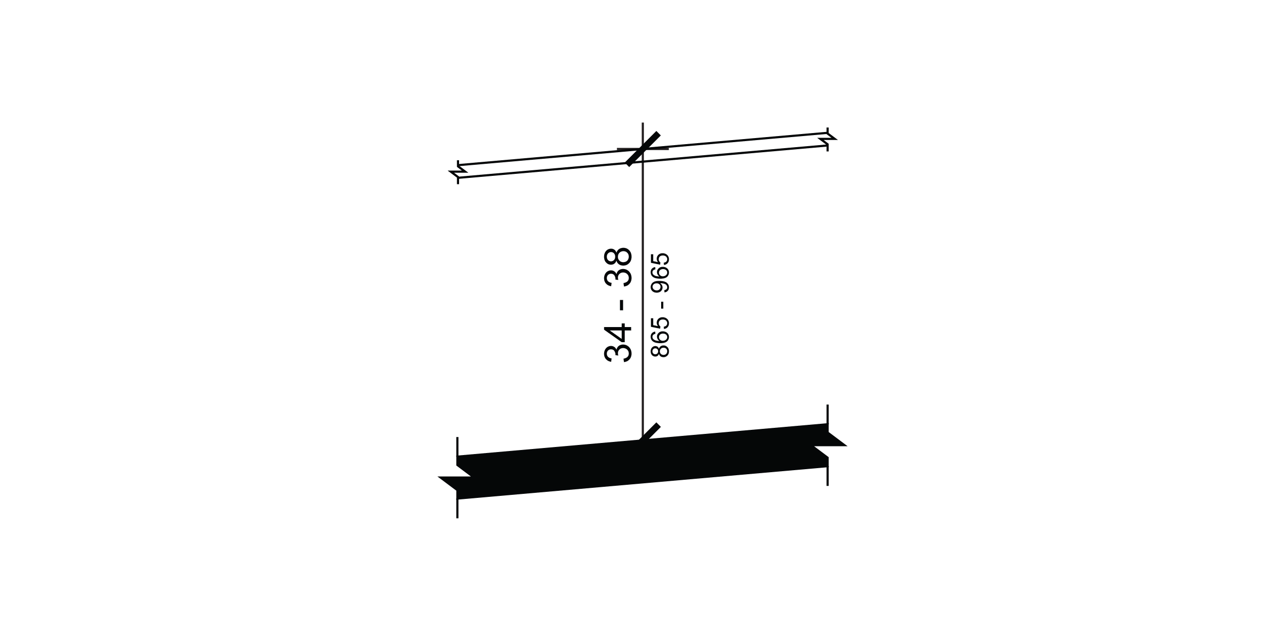
R409.5 Clearance
Clearance between handrail gripping surfaces and adjacent surfaces shall be 1½ inches (38 mm) minimum.
R409.6 Gripping Surface
Handrail gripping surfaces shall be continuous along their length and shall not be obstructed along their tops or sides. The bottoms of handrail gripping surfaces shall not be obstructed for more than 20 percent of their length. Where provided, horizontal projections shall occur 1½ inches (38 mm) minimum below the bottom of the handrail gripping surface.
R409.7 Cross Section
Handrail gripping surfaces shall have a cross section complying with R409.7.1 or R409.7.2. Where expansion joints are necessary for large spans of handrails, the expansion joint cross section is permitted to be smaller than the specified cross section diameters for 1 inch (25 mm) maximum in length.
R409.7.1 Circular Cross Section
Handrail gripping surfaces with a circular cross section shall have an outside diameter of 1¼ inches (32 mm) minimum and 2 inches (51 mm) maximum.
R409.7.2 Non-Circular Cross Section
Handrail gripping surfaces with a non-circular cross section shall have a perimeter dimension of 4 inches (100 mm) minimum and 6¼ inches (160 mm) maximum, and a cross-section dimension of 2¼ inches (57 mm) maximum.
R409.8 Surfaces
Handrail gripping surfaces and any surfaces adjacent to them shall be free of sharp or abrasive elements and shall have rounded edges.
R409.9 Fittings
Handrails shall not rotate within their fittings. Where expansion joints are necessary for large spans of handrails, the expansion joint is permitted to rotate in its fitting.
R409.10 Handrail Extensions
Handrail gripping surfaces shall extend beyond and in the same direction of ramp runs and stair flights in accordance with R409.10. Handrail extensions shall not extend into the roadway or pedestrian circulation path. In alterations, if handrail extensions complying with R409.10 would reduce the clear width of a pedestrian access route, they shall extend as far as possible without reducing the clear width of the pedestrian access route.
EXCEPTION: Extensions shall not be required for continuous handrails at the inside turn of switchback or dogleg ramps and stairs.
R409.10.1 Top and Bottom Extension at Ramps
Ramp handrails shall extend horizontally above the landing for 12 inches (305 mm) minimum beyond the top and bottom of ramp runs. Extensions shall return to a wall, guard, or the landing surface, or shall be continuous to the handrail of an adjacent ramp run.
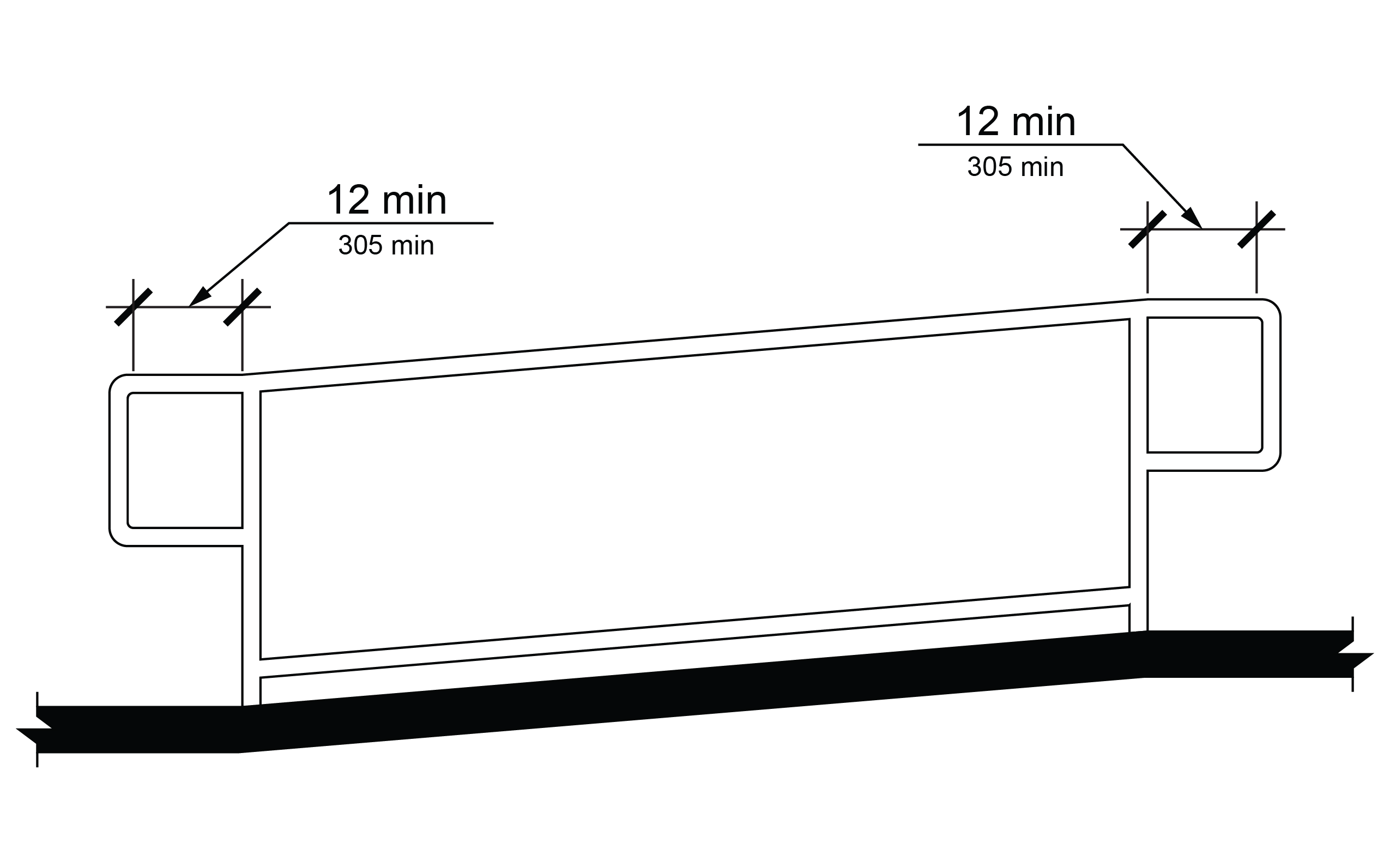
R409.10.2 Top Extension at Stairs
At the top of a stair flight, handrails shall extend horizontally above the landing for 12 inches (305 mm) minimum beginning directly above the first riser nosing. Extensions shall return to a wall, guard, or the landing surface, or shall be continuous to the handrail of an adjacent stair flight.
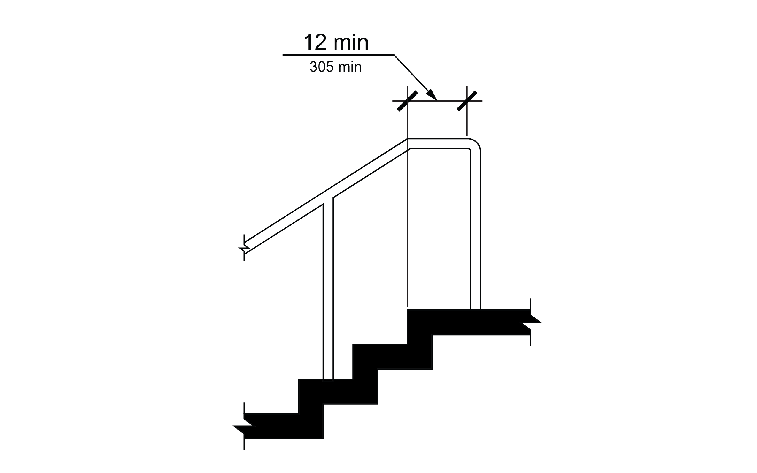
R409.10.3 Bottom Extension at Stairs
At the bottom of a stair flight, handrails shall extend at the slope of the stair flight for a horizontal distance at least equal to one tread depth beyond the last riser nosing. Extensions shall return to a wall, guard, or the landing surface, or shall be continuous to the handrail of an adjacent stair flight.
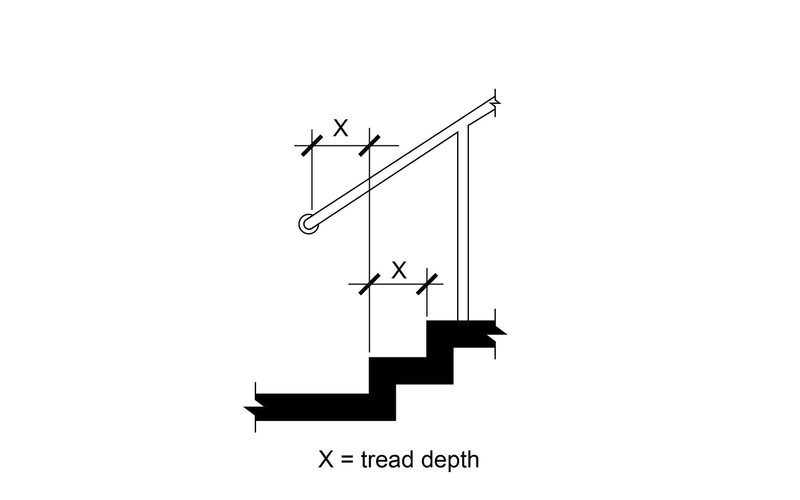
R410 Visual Characters on Signs
R410.1 General
Visual characters on signs shall comply with R410.
R410.2 Finish and Contrast
Characters and their background shall have a non-glare finish. Characters shall contrast with their background with either light characters on a dark background or dark characters on a light background.
R410.3 Case
Characters shall be uppercase or lowercase or a combination of both.
R410.4 Style
Characters shall be conventional in form. Characters shall not be italic, oblique, script, highly decorative, or of other unusual forms.
R410.5 Character Proportions
Characters shall be selected from fontsmwhere the width of the uppercase letter “O” is 55 percent minimum and 110 percent maximum of the height of the uppercase letter “I”.
R410.6 Character Height
Minimum character height shall comply with Table R410.6. Viewing distance shall be measured as the horizontal distance between the character and an obstruction preventing further approach towards the sign. Character height shall be based on the uppercase letter “I”.
R410.6 Visual Character Height
Table R410.6 Visual Character Height
| Height to Finish Surface from Baseline of Character | Horizontal Viewing Distance | Minimum Character Height |
|---|---|---|
| 40 inches (1015 mm) to less than or equal to 70 inches (1780 mm) | Less than 72 inches (1830 mm) | 5/8 inch (16 mm) |
| 40 inches (1015 mm) to less than or equal to 70 inches (1780 mm) | 72 inches (1830 mm) and greater | 5/8 inch (16 mm), plus 1/8 inch (3.2 mm) per foot (305 mm) of viewing distance above 72 inches (1830 mm) |
| Greater than 70 inches (1780 mm) to less than or equal to 120 inches (3050 mm) | Less than 180 inches (4570 mm) | 2 inches (51 mm) |
| Greater than 70 inches (1780 mm) to less than or equal to 120 inches (3050 mm) | 180 inches (4570 mm) and greater | 2 inches (51 mm), plus 1/8 inch (3.2 mm) per foot (305 mm) of viewing distance above 180 inches (4570 mm) |
| Greater than 120 inches (3050 mm) | Less than 21 feet (6400 mm) | 3 inches (75 mm) |
| Greater than 120 inches (3050 mm) | 21 feet (6400 mm) and greater | 3 inches (75 mm), plus 1/8 inch (3.2 mm) per foot (305 mm) of viewing distance above 21 feet (6400 mm) |
R410.7 Stroke Thickness
Stroke thickness of the uppercase letter “I” shall be 10 percent minimum and 30 percent maximum of the height of the character.
R410.8 Character Spacing
Character spacing shall be measured between the two closest points of adjacent characters, excluding word spaces. Spacing between individual characters shall be 10 percent minimum and 35 percent maximum of character height.
R410.9 Line Spacing
Spacing between the baselines of separate lines of characters within a message shall be 135 percent minimum and 170 percent maximum of the character height.
R410.10 Height from Ground Surface
Visual characters shall be 40 inches (1015 mm) minimum above the ground surface.
R411 International Symbol of Accessibility
R411.1 General
The International Symbol of Accessibility shall comply with R411 and Figure R411.
R411.2 Finish and Contrast
The symbol and its background shall have a non-glare finish. The symbol shall contrast with its background with either a light symbol on a dark background or a dark symbol on a light background.
Figure R411 – International Symbol of Accessibility