
701 General
701.1 Scope
The provisions of Chapter 7 shall apply where required by Chapter 2 or where referenced by a requirement in this document.
702 Fire Alarm Systems
702.1 General
Fire alarm systems shall have permanently installed audible and visible alarms complying with NFPA 72 (1999 or 2002 edition) (incorporated by reference, see “Referenced Standards” in Chapter 1), except that the maximum allowable sound level of audible notification appliances complying with section 4-3.2.1 of NFPA 72 (1999 edition) shall have a sound level no more than 110 dB at the minimum hearing distance from the audible appliance. In addition, alarms in guest rooms required to provide communication features shall comply with sections 4-3 and 4-4 of NFPA 72 (1999 edition) or sections 7.4 and 7.5 of NFPA 72 (2002 edition).
EXCEPTION: Fire alarm systems in medical care facilities shall be permitted to be provided in accordance with industry practice.
703 Signs
703.1 General
Signs shall comply with 703. Where both visual and tactile characters are required, either one sign with both visual and tactile characters, or two separate signs, one with visual, and one with tactile characters, shall be provided.
703.2 Raised Characters
Raised characters shall comply with 703.2 and shall be duplicated in braille complying with 703.3. Raised characters shall be installed in accordance with 703.4.
Advisory 703.2 Raised Characters. Signs that are designed to be read by touch should not have sharp or abrasive edges.
703.2.1 Depth
Raised characters shall be 1/32 inch (0.8 mm) minimum above their background.
703.2.2 Case
Characters shall be uppercase.
703.2.3 Style
Characters shall be sans serif. Characters shall not be italic, oblique, script, highly decorative, or of other unusual forms.
703.2.4 Character Proportions
Characters shall be selected from fonts where the width of the uppercase letter “O” is 55 percent minimum and 110 percent maximum of the height of the uppercase letter “I”.
703.2.5 Character Height
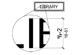
Character height measured vertically from the baseline of the character shall be 5/8 inch (16 mm) minimum and 2 inches (51 mm) maximum based on the height of the uppercase letter “I”.
EXCEPTION: Where separate raised and visual characters with the same information are provided, raised character height shall be permitted to be ½ inch (13 mm) minimum.
View detailed image description
An Enlarged detail shows the character height measured from the baseline of the character is five-eighths to 2 inches (16 to 51 mm) based on the uppercase letter I.
703.2.6 Stroke Thickness
Stroke thickness of the uppercase letter “I” shall be 15 percent maximum of the height of the character.
703.2.7 Character Spacing
Character spacing shall be measured between the two closest points of adjacent raised characters within a message, excluding word spaces. Where characters have rectangular cross sections, spacing between individual raised characters shall be 1/8 inch (3.2 mm) minimum and 4 times the raised character stroke width maximum. Where characters have other cross sections, spacing between individual raised characters shall be 1/16 inch (1.6 mm) minimum and 4 times the raised character stroke width maximum at the base of the cross sections, and 1/8 inch (3.2 mm) minimum and 4 times the raised character stroke width maximum at the top of the cross sections. Characters shall be separated from raised borders and decorative elements 3/8 inch (9.5 mm) minimum.
703.2.8 Line Spacing
Spacing between the baselines of separate lines of raised characters within a message shall be 135 percent minimum and 170 percent maximum of the raised character height.
703.3 Braille
Braille shall be contracted (Grade 2) and shall comply with 703.3 and 703.4.
703.3.1 Dimensions and Capitalization
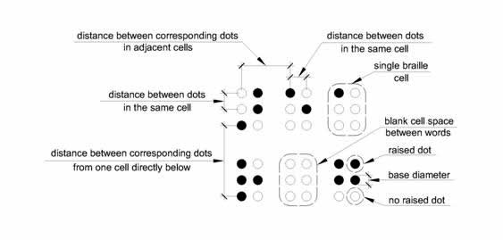
Braille dots shall have a domed or rounded shape and shall comply with Table 703.3.1. The indication of an uppercase letter or letters shall only be used before the first word of sentences, proper nouns and names, individual letters of the alphabet, initials, and acronyms.
| Measurement Range | Minimum in Inches Maximum in Inches |
|---|---|
| ¹ Measured center to center. | |
| Dot base diameter | 0.059 (1.5 mm) to 0.063 (1.6 mm) |
| Distance between two dots in the same cell ¹ |
0.090 (2.3 mm) to 0.100 (2.5 mm) |
| Distance between corresponding dots in adjacent cells ¹ |
0.241 (6.1 mm) to 0.300 (7.6 mm) |
| Dot height | 0.025 (0.6 mm) to 0.037 (0.9 mm) |
| Distance between corresponding dots from one cell directly below ¹ |
0.395 (10 mm) to 0.400 (10.2 mm) |
View detailed image description
Six Braille cells are shown indicating what is meant by dot diameter, distance between dots in the same cell, distance between dots in adjacent cells, distance between corresponding dots from one cell directly below in Table 703.3.1.
703.3.2 Position
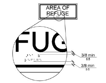
Braille shall be positioned below the corresponding text. If text is multi-lined, braille shall be placed below the entire text. Braille shall be separated 3/8 inch (9.5 mm) minimum from any other tactile characters and 3/8 inch (9.5 mm) minimum from raised borders and decorative elements.
EXCEPTION: Braille provided on elevator car controls shall be separated 3/16 inch (4.8 mm) minimum and shall be located either directly below or adjacent to the corresponding raised characters or symbols.
View detailed image description
An enlarged detail shows Braille dots positioned 3/8 inch (9.5 mm) minimum below tactile letters and 3/8 inch (9.5 mm) minimum separation from the sign border.
703.4 Installation Height and Location
Signs with tactile characters shall comply with 703.4.
703.4.1 Height Above Finish Floor or Ground
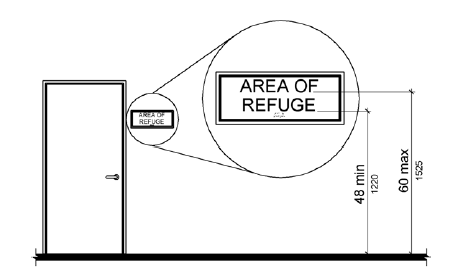
Tactile characters on signs shall be located 48 inches (1220 mm) minimum above the finish floor or ground surface, measured from the baseline of the lowest tactile character and 60 inches (1525 mm) maximum above the finish floor or ground surface, measured from the baseline of the highest tactile character.
EXCEPTION: Tactile characters for elevator car controls shall not be required to comply with 703.4.1.
View detailed image description
A tactile sign is shown mounted with the baseline of the lowest characters 48 inches (1220 mm) minimum and the baseline of the highest characters 60 inches (1525 mm) maximum above the finish floor.
703.4.2 Location
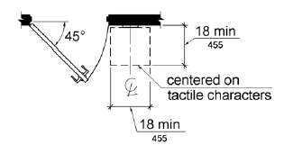
Where a tactile sign is provided at a door, the sign shall be located alongside the door at the latch side. Where a tactile sign is provided at double doors with one active leaf, the sign shall be located on the inactive leaf. Where a tactile sign is provided at double doors with two active leafs, the sign shall be located to the right of the right hand door. Where there is no wall space at the latch side of a single door or at the right side of double doors, signs shall be located on the nearest adjacent wall. Signs containing tactile characters shall be located so that a clear floor space of 18 inches (455 mm) minimum by 18 inches (455 mm) minimum, centered on the tactile characters, is provided beyond the arc of any door swing between the closed position and 45 degree open position.
EXCEPTION: Signs with tactile characters shall be permitted on the push side of doors with closers and without hold-open devices.
View detailed image description
A sign with tactile characters is mounted so that clear floor space 18 by 18 inches (455 by 455 mm) minimum, centered on the tactile characters, is provided beyond the arc of any door swing between the closed position and 45 degree open position.
703.5 Visual Characters
Visual characters shall comply with 703.5.
EXCEPTION: Where visual characters comply with 703.2 and are accompanied by braille complying with 703.3, they shall not be required to comply with 703.5.2 through 703.5.9.
703.5.1 Finish and Contrast
Characters and their background shall have a non-glare finish. Characters shall contrast with their background with either light characters on a dark background or dark characters on a light background.
Advisory 703.5.1 Finish and Contrast. Signs are more legible for persons with low vision when characters contrast as much as possible with their background. Additional factors affecting the ease with which the text can be distinguished from its background include shadows cast by lighting sources, surface glare, and the uniformity of the text and its background colors and textures.
703.5.2 Case
Characters shall be uppercase or lowercase or a combination of both.
703.5.3 Style
Characters shall be conventional in form. Characters shall not be italic, oblique, script, highly decorative, or of other unusual forms.
703.5.4 Character Proportions
Characters shall be selected from fonts where the width of the uppercase letter “O” is 55 percent minimum and 110 percent maximum of the height of the uppercase letter “I”.
703.5.5 Character Height
Minimum character height shall comply with Table 703.5.5. Viewing distance shall be measured as the horizontal distance between the character and an obstruction preventing further approach towards the sign. Character height shall be based on the uppercase letter “I”.
| Height to Finish Floor or Ground from Baseline of Character |
Horizontal Viewing Distance | Minimum Character Height |
|---|---|---|
| 40 inches (1015 mm) to less than or equal to 70 inches (1780 mm) |
less than 72 inches (1830 mm) | 5/8 inch (16 mm) |
| 72 inches (1830 mm) and greater | 5/8 inch (16 mm), plus 1/8 inch (3.2 mm) per foot (305 mm) of viewing distance above 72 inches (1830 mm) |
|
| Greater than 70 inches (1780 mm) to less than or equal to 120 inches (3050 mm) |
less than 180 inches (4570 mm) | 2 inches (51 mm) |
| 180 inches (4570 mm) and greater | 2 inches (51 mm), plus 1/8 inch (3.2 mm) per foot (305 mm) of viewing distance above 180 inches (4570 mm) |
|
| greater than 120 inches (3050 mm) | less than 21 feet (6400 mm) | 3 inches (75 mm) |
| 21 feet (6400 mm) and greater | 3 inches (75 mm), plus 1/8 inch (3.2 mm) per foot (305 mm) of viewing distance above 21 feet (6400 mm) |
703.5.6 Height From Finish Floor or Ground
Visual characters shall be 40 inches (1015 mm) minimum above the finish floor or ground.
EXCEPTION: Visual characters indicating elevator car controls shall not be required to comply with 703.5.6.
703.5.7 Stroke Thickness
Stroke thickness of the uppercase letter “I” shall be 10 percent minimum and 30 percent maximum of the height of the character.
703.5.8 Character Spacing
Character spacing shall be measured between the two closest points of adjacent characters, excluding word spaces. Spacing between individual characters shall be 10 percent minimum and 35 percent maximum of character height.
703.5.9 Line Spacing
Spacing between the baselines of separate lines of characters within a message shall be 135 percent minimum and 170 percent maximum of the character height.
703.6 Pictograms
Pictograms shall comply with 703.6.
703.6.1 Pictogram Field
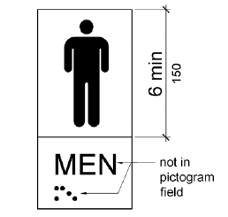
Pictograms shall have a field height of 6 inches (150 mm) minimum. Characters and braille shall not be located in the pictogram field.
View detailed image description
The field height for a men’s room pictogram is shown to be 6 inches (150 mm) minimum. Tactile and Braille characters are located below, outside the pictogram field.
703.6.2 Finish and Contrast
Pictograms and their field shall have a non-glare finish. Pictograms shall contrast with their field with either a light pictogram on a dark field or a dark pictogram on a light field.
Advisory 703.6.2 Finish and Contrast. Signs are more legible for persons with low vision when characters contrast as much as possible with their background. Additional factors affecting the ease with which the text can be distinguished from its background include shadows cast by lighting sources, surface glare, and the uniformity of the text and background colors and textures.
703.6.3 Text Descriptors
Pictograms shall have text descriptors located directly below the pictogram field. Text descriptors shall comply with 703.2, 703.3 and 703.4.
703.7 Symbols of Accessibility
Symbols of accessibility shall comply with 703.7.
703.7.1 Finish and Contrast
Symbols of accessibility and their background shall have a non-glare finish. Symbols of accessibility shall contrast with their background with either a light symbol on a dark background or a dark symbol on a light background.
Advisory 703.7.1 Finish and Contrast. Signs are more legible for persons with low vision when characters contrast as much as possible with their background. Additional factors affecting the ease with which the text can be distinguished from its background include shadows cast by lighting sources, surface glare, and the uniformity of the text and background colors and textures.
703.7.2 Symbols
703.7.2.1 International Symbol of Accessibility
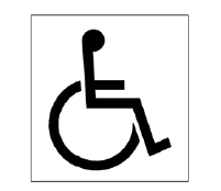
The International Symbol of Accessibility shall comply with Figure 703.7.2.1.
View detailed image description
Pictogram that shows the simplified profile of a person seated in a wheelchair.
703.7.2.2 International Symbol of TTY
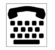
The International Symbol of TTY shall comply with Figure 703.7.2.2.
View detailed image description
Pictogram of a TTY showing the keyboard and space bar typical of most devices and the shape of a telephone handset at the top.
703.7.2.3 Volume Control Telephones
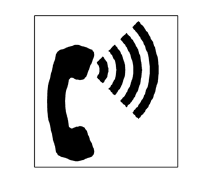
Telephones with a volume control shall be identified by a pictogram of a telephone handset with radiating sound waves on a square field such as shown in Figure 703.7.2.3.
View detailed image description
Pictogram of a telephone handset in profile with radiating sound waves.
703.7.2.4 Assistive Listening Systems
Assistive listening systems shall be identified by the International Symbol of Access for Hearing Loss complying with Figure 703.7.2.4.

View detailed image description
Pictogram with the shape of an ear and a bar diagonally across the shape.
704 Telephones
704.1 General
Public telephones shall comply with 704.
704.2 Wheelchair Accessible Telephones
Wheelchair accessible telephones shall comply with 704.2.
704.2.1 Clear Floor or Ground Space
A clear floor or ground space complying with 305 shall be provided. The clear floor or ground space shall not be obstructed by bases, enclosures, or seats.
Advisory 704.2.1 Clear Floor or Ground Space. Because clear floor and ground space is required to be unobstructed, telephones, enclosures and related telephone book storage cannot encroach on the required clear floor or ground space and must comply with the provisions for protruding objects. (See Section 307).
704.2.1.1 Parallel Approach
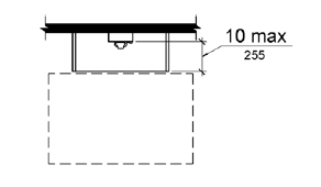
Where a parallel approach is provided, the distance from the edge of the telephone enclosure to the face of the telephone unit shall be 10 inches (255 mm) maximum.
View detailed image description
The maximum distance from the face of the telephone to the edge of the telephone enclosure is 10 inches (255 mm). Clear floor space for a parallel approach is located in front of the enclosure.
704.2.1.2 Forward Approach
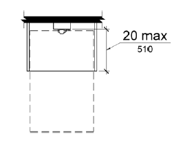
Where a forward approach is provided, the distance from the front edge of a counter within the telephone enclosure to the face of the telephone unit shall be 20 inches (510 mm) maximum.
View detailed image description
The maximum distance from the front edge of a counter within the telephone enclosure to the face of the telephone is 20 inches (510 mm). The telephone enclosure overlaps the clear floor space for a forward approach.
704.2.2 Operable Parts
Operable parts shall comply with 309. Telephones shall have push-button controls where such service is available.
704.2.3 Telephone Directories
Telephone directories, where provided, shall be located in accordance with 309.
704.2.4 Cord Length
The cord from the telephone to the handset shall be 29 inches (735 mm) long minimum.
704.3 Volume Control Telephones
Public telephones required to have volume controls shall be equipped with a receive volume control that provides a gain adjustable up to 20 dB minimum. For incremental volume control, provide at least one intermediate step of 12 dB of gain minimum. An automatic reset shall be provided.
Advisory 704.3 Volume Control Telephones. Amplifiers on pay phones are located in the base or the handset or are built into the telephone. Most are operated by pressing a button or key. If the microphone in the handset is not being used, a mute button that temporarily turns off the microphone can also reduce the amount of background noise which the person hears in the earpiece. If a volume adjustment is provided that allows the user to set the level anywhere from the base volume to the upper requirement of 20 dB, there is no need to specify a lower limit. If a stepped volume control is provided, one of the intermediate levels must provide 12 dB of gain. Consider compatibility issues when matching an amplified handset with a phone or phone system. Amplified handsets that can be switched with pay telephone handsets are available. Portable and in-line amplifiers can be used with some phones but are not practical at most public phones covered by these requirements.
704.4 TTYs
TTYs required at a public pay telephone shall be permanently affixed within, or adjacent to, the telephone enclosure. Where an acoustic coupler is used, the telephone cord shall be sufficiently long to allow connection of the TTY and the telephone receiver.
Advisory 704.4 TTYs. Ensure that sufficient electrical service is available where TTYs are to be installed.
704.4.1 Height
When in use, the touch surface of TTY keypads shall be 34 inches (865 mm) minimum above the finish floor.
EXCEPTION: Where seats are provided, TTYs shall not be required to comply with 704.4.1.
Advisory 704.4.1 Height. A telephone with a TTY installed underneath cannot also be a wheelchair accessible telephone because the required 34 inches (865 mm) minimum keypad height can cause the highest operable part of the telephone, usually the coin slot, to exceed the maximum permitted side and forward reach ranges. (See Section 308).
Advisory 704.4.1 Height Exception. While seats are not required at TTYs, reading and typing at a TTY is more suited to sitting than standing. Facilities that often provide seats at TTY's include, but are not limited to, airports and other passenger terminals or stations, courts, art galleries, and convention centers.
704.5 TTY Shelf
Public pay telephones required to accommodate portable TTYs shall be equipped with a shelf and an electrical outlet within or adjacent to the telephone enclosure. The telephone handset shall be capable of being placed flush on the surface of the shelf. The shelf shall be capable of accommodating a TTY and shall have 6 inches (150 mm) minimum vertical clearance above the area where the TTY is to be placed.
705 Detectable Warnings
705.1 General
Detectable warnings shall consist of a surface of truncated domes and shall comply with 705.
705.1.1 Dome Size
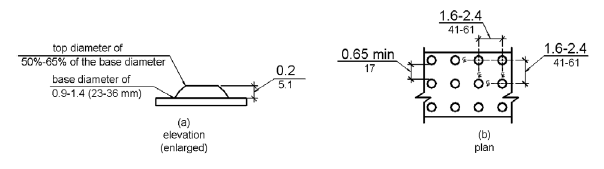
Truncated domes in a detectable warning surface shall have a base diameter of 0.9 inch (23 mm) minimum and 1.4 inches (36 mm) maximum, a top diameter of 50 percent of the base diameter minimum to 65 percent of the base diameter maximum, and a height of 0.2 inch (5.1 mm).
705.1.2 Dome Spacing
Truncated domes in a detectable warning surface shall have a center-to-center spacing of 1.6 inches (41 mm) minimum and 2.4 inches (61 mm) maximum, and a base-to-base spacing of 0.65 inch (17 mm) minimum, measured between the most adjacent domes on a square grid.
705.1.3 Contrast
Detectable warning surfaces shall contrast visually with adjacent walking surfaces either light-on-dark, or dark-on-light.
View detailed image description
Figure (a) is an enlarged elevation drawing of a single dome showing the base diameter as 0.9 to 1.4 inches (23 to 36 mm) and the top surface as having a diameter of 50% to 65% of the base. The dome height is 0.2 inch (5.1 mm).
Figure (b) is a plan view of a detectable warning surface showing the center-to-center dome spacing of 1.6 to 2.4 inches (41 to 61 mm) with a base-to-base separation of 0.65 inch (17 mm) minimum.
705.2 Platform Edges
Detectable warning surfaces at platform boarding edges shall be 24 inches (610 mm) wide and shall extend the full length of the public use areas of the platform.
706 Assistive Listening Systems
706.1 General
Assistive listening systems required in assembly areas shall comply with 706.
Advisory 706.1 General. Assistive listening systems are generally categorized by their mode of transmission. There are hard-wired systems and three types of wireless systems: induction loop, infrared, and FM radio transmission. Each has different advantages and disadvantages that can help determine which system is best for a given application. For example, an FM system may be better than an infrared system in some open-air assemblies since infrared signals are less effective in sunlight. On the other hand, an infrared system is typically a better choice than an FM system where confidential transmission is important because it will be contained within a given space.
The technical standards for assistive listening systems describe minimum performance levels for volume, interference, and distortion. Sound pressure levels (SPL), expressed in decibels, measure output sound volume. Signal-to-noise ratio (SNR or S/N), also expressed in decibels, represents the relationship between the loudness of a desired sound (the signal) and the background noise in a space or piece of equipment. The higher the SNR, the more intelligible the signal. The peak clipping level limits the distortion in signal output produced when high-volume sound waves are manipulated to serve assistive listening devices.
Selecting or specifying an effective assistive listening system for a large or complex venue requires assistance from a professional sound engineer. The Access Board has published technical assistance on assistive listening devices and systems.
706.2 Receiver Jacks
Receivers required for use with an assistive listening system shall include a 1/8 inch (3.2 mm) standard mono jack.
706.3 Receiver Hearing-Aid Compatibility
Receivers required to be hearing-aid compatible shall interface with telecoils in hearing aids through the provision of neckloops.
Advisory 706.3 Receiver Hearing-Aid Compatibility. Neckloops and headsets that can be worn as neckloops are compatible with hearing aids. Receivers that are not compatible include earbuds, which may require removal of hearing aids, earphones, and headsets that must be worn over the ear, which can create disruptive interference in the transmission and can be uncomfortable for people wearing hearing aids.
706.4 Sound Pressure Level
Assistive listening systems shall be capable of providing a sound pressure level of 110 dB minimum and 118 dB maximum with a dynamic range on the volume control of 50 dB.
706.5 Signal-to-Noise Ratio
The signal-to-noise ratio for internally generated noise in assistive listening systems shall be 18 dB minimum.
706.6 Peak Clipping Level
Peak clipping shall not exceed 18 dB of clipping relative to the peaks of speech.
707 Automatic Teller Machines and Fare Machines
Advisory 707 Automatic Teller Machines and Fare Machines. Interactive transaction machines (ITMs), other than ATMs, are not covered by Section 707. However, for entities covered by the ADA, the Department of Justice regulations that implement the ADA provide additional guidance regarding the relationship between these requirements and elements that are not directly addressed by these requirements. Federal procurement law requires that ITMs purchased by the Federal government comply with standards issued by the Access Board under Section 508 of the Rehabilitation Act of 1973, as amended. This law covers a variety of products, including computer hardware and software, websites, phone systems, fax machines, copiers, and similar technologies. For more information on Section 508 consult the Access Board's website at www.access-board.gov.
707.1 General
Automatic teller machines and fare machines shall comply with 707.
Advisory 707.1 General. If farecards have one tactually distinctive corner they can be inserted with greater accuracy. Token collection devices that are designed to accommodate tokens which are perforated can allow a person to distinguish more readily between tokens and common coins. Place accessible gates and fare vending machines in close proximity to other accessible elements when feasible so the facility is easier to use.
707.2 Clear Floor or Ground Space
A clear floor or ground space complying with 305 shall be provided.
EXCEPTION: Clear floor or ground space shall not be required at drive-up only automatic teller machines and fare machines.
707.3 Operable Parts
Operable parts shall comply with 309. Unless a clear or correct key is provided, each operable part shall be able to be differentiated by sound or touch, without activation.
EXCEPTION: Drive-up only automatic teller machines and fare machines shall not be required to comply with 309.2 and 309.3.
707.4 Privacy
Automatic teller machines shall provide the opportunity for the same degree of privacy of input and output available to all individuals.
Advisory 707.4 Privacy. In addition to people who are blind or visually impaired, people with limited reach who use wheelchairs or have short stature, who cannot effectively block the ATM screen with their bodies, may prefer to use speech output. Speech output users can benefit from an option to render the visible screen blank, thereby affording them greater personal security and privacy.
707.5 Speech Output
Machines shall be speech enabled. Operating instructions and orientation, visible transaction prompts, user input verification, error messages, and all displayed information for full use shall be accessible to and independently usable by individuals with vision impairments. Speech shall be delivered through a mechanism that is readily available to all users, including but not limited to, an industry standard connector or a telephone handset. Speech shall be recorded or digitized human, or synthesized.
EXCEPTIONS:
- Audible tones shall be permitted instead of speech for visible output that is not displayed for security purposes, including but not limited to, asterisks representing personal identification numbers.
- Advertisements and other similar information shall not be required to be audible unless they convey information that can be used in the transaction being conducted.
- Where speech synthesis cannot be supported, dynamic alphabetic output shall not be required to be audible.
Advisory 707.5 Speech Output. If an ATM provides additional functions such as dispensing coupons, selling theater tickets, or providing copies of monthly statements, all such functions must be available to customers using speech output. To avoid confusion at the ATM, the method of initiating the speech mode should be easily discoverable and should not require specialized training. For example, if a telephone handset is provided, lifting the handset can initiate the speech mode.
707.5.1 User Control
Speech shall be capable of being repeated or interrupted. Volume control shall be provided for the speech function.
EXCEPTION: Speech output for any single function shall be permitted to be automatically interrupted when a transaction is selected.
707.5.2 Receipts
Where receipts are provided, speech output devices shall provide audible balance inquiry information, error messages, and all other information on the printed receipt necessary to complete or verify the transaction.
EXCEPTIONS:
- Machine location, date and time of transaction, customer account number, and the machine identifier shall not be required to be audible.
- Information on printed receipts that duplicates information available on-screen shall not be required to be presented in the form of an audible receipt.
- Printed copies of bank statements and checks shall not be required to be audible.
707.6 Input
Input devices shall comply with 707.6.
707.6.1 Input Controls
At least one tactilely discernible input control shall be provided for each function. Where provided, key surfaces not on active areas of display screens, shall be raised above surrounding surfaces. Where membrane keys are the only method of input, each shall be tactilely discernable from surrounding surfaces and adjacent keys.
707.6.2 Numeric Keys
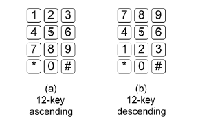
Numeric keys shall be arranged in a 12-key ascending or descending telephone keypad layout. The number five key shall be tactilely distinct from the other keys.
Advisory 707.6.2 Numeric Keys. Telephone keypads and computer keyboards differ in one significant feature, ascending versus descending numerical order. Both types of keypads are acceptable, provided the computer-style keypad is organized similarly to the number pad located at the right on most computer keyboards, and does not resemble the line of numbers located above the computer keys.
View detailed image description
Figure (a) shows a 12-key ascending layout with “1” in the upper left corner, such as a telephone. Figure (b) shows a descending layout with “7” in the upper left corner, such as a computer numeric keypad.
707.6.3 Function Keys
Function keys shall comply with 707.6.3.
707.6.3.1 Contrast
Function keys shall contrast visually from background surfaces. Characters and symbols on key surfaces shall contrast visually from key surfaces. Visual contrast shall be either light-on-dark or dark-on-light.
EXCEPTION: Tactile symbols required by 707.6.3.2 shall not be required to comply with 707.6.3.1.
707.6.3.2 Tactile Symbols
Function key surfaces shall have tactile symbols as follows: Enter or Proceed key: raised circle; Clear or Correct key: raised left arrow; Cancel key: raised letter ex; Add Value key: raised plus sign; Decrease Value key: raised minus sign.
707.7 Display Screen
The display screen shall comply with 707.7.
EXCEPTION: Drive-up only automatic teller machines and fare machines shall not be required to comply with 707.7.1.
707.7.1 Visibility
The display screen shall be visible from a point located 40 inches (1015 mm) above the center of the clear floor space in front of the machine.
707.7.2 Characters
Characters displayed on the screen shall be in a sans serif font. Characters shall be 3/16 inch (4.8 mm) high minimum based on the uppercase letter “I”. Characters shall contrast with their background with either light characters on a dark background or dark characters on a light background.
707.8 Braille Instructions
Braille instructions for initiating the speech mode shall be provided. Braille shall comply with 703.3.
708 Two-Way Communication Systems
708.1 General
Two-way communication systems shall comply with 708.
Advisory 708.1 General. Devices that do not require handsets are easier to use by people who have a limited reach.
708.2 Audible and Visual Indicators
The system shall provide both audible and visual signals.
Advisory 708.2 Audible and Visual Indicators. A light can be used to indicate visually that assistance is on the way. Signs indicating the meaning of visual signals should be provided.
708.3 Handsets
Handset cords, if provided, shall be 29 inches (735 mm) long minimum.
708.4 Residential Dwelling Unit Communication Systems
Communications systems between a residential dwelling unit and a site, building, or floor entrance shall comply with 708.4.
708.4.1 Common Use or Public Use System Interface
The common use or public use system interface shall include the capability of supporting voice and TTY communication with the residential dwelling unit interface.
708.4.2 Residential Dwelling Unit Interface
The residential dwelling unit system interface shall include a telephone jack capable of supporting voice and TTY communication with the common use or public use system interface.