
301 General
301.1 Scope
The provisions of Chapter 3 shall apply where required by Chapter 2 or where referenced by a requirement in this document.
302 Floor or Ground Surfaces
302.1 General
Floor and ground surfaces shall be stable, firm, and slip resistant and shall comply with 302.
EXCEPTIONS:
- Within animal containment areas, floor and ground surfaces shall not be required to be stable, firm, and slip resistant.
- Areas of sport activity shall not be required to comply with 302.
Advisory 302.1 General. A stable surface is one that remains unchanged by contaminants or applied force, so that when the contaminant or force is removed, the surface returns to its original condition. A firm surface resists deformation by either indentations or particles moving on its surface. A slip-resistant surface provides sufficient frictional counterforce to the forces exerted in walking to permit safe ambulation.
302.2 Carpet
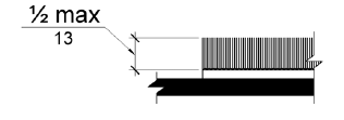
Carpet or carpet tile shall be securely attached and shall have a firm cushion, pad, or backing or no cushion or pad. Carpet or carpet tile shall have a level loop, textured loop, level cut pile, or level cut/uncut pile texture. Pile height shall be ½ inch (13 mm) maximum. Exposed edges of carpet shall be fastened to floor surfaces and shall have trim on the entire length of the exposed edge. Carpet edge trim shall comply with 303.
Advisory 302.2 Carpet. Carpets and permanently affixed mats can significantly increase the amount of force (roll resistance) needed to propel a wheelchair over a surface. The firmer the carpeting and backing, the lower the roll resistance. A pile thickness up to ½ inch (13 mm) (measured to the backing, cushion, or pad) is allowed, although a lower pile provides easier wheelchair maneuvering. If a backing, cushion or pad is used, it must be firm. Preferably, carpet pad should not be used because the soft padding increases roll resistance.
View detailed image description
Carpet is shown in cross section with a pile height of ½ inch (13 mm) maximum, measured from the backing.
302.3 Openings
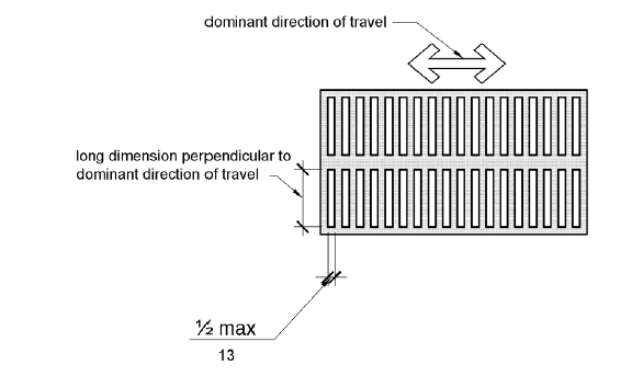
Openings in floor or ground surfaces shall not allow passage of a sphere more than ½ inch (13 mm) diameter except as allowed in 407.4.3, 409.4.3, 410.4, 810.5.3 and 810.10. Elongated openings shall be placed so that the long dimension is perpendicular to the dominant direction of travel.
View detailed image description
Elongated openings, such as in a grating, are shown in plan view with openings ½ inch (13 mm) maximum in one dimension. The other dimension is longer (unspecified) and is perpendicular to the dominant direction of travel.
303 Changes in Level
303.1 General
Where changes in level are permitted in floor or ground surfaces, they shall comply with 303.
EXCEPTIONS:
- Animal containment areas shall not be required to comply with 303.
- Areas of sport activity shall not be required to comply with 303.
303.2 Vertical
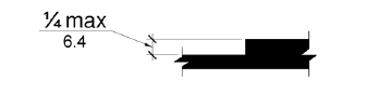
Changes in level of ¼ inch (6.4 mm) high maximum shall be permitted to be vertical.
View detailed image description
Elevation drawing of a change in level between the surfaces of two parallel planes with a vertical edge that is ¼ inch (6.4 mm) high maximum.
303.3 Beveled
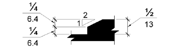
Changes in level between ¼ inch (6.4 mm) high minimum and ½ inch (13 mm) high maximum shall be beveled with a slope not steeper than 1:2.
Advisory 303.3 Beveled. A change in level of ½ inch (13 mm) is permitted to be ¼ inch (6.4 mm) vertical plus ¼ inch (6.4 mm) beveled. However, in no case may the combined change in level exceed ½ inch (13 mm). Changes in level exceeding ½ inch (13 mm) must comply with 405 (Ramps) or 406 (Curb Ramps).
View detailed image description
Elevation drawing of a change in level ¼ to ½ inches (6.4 - 13 mm) high that is beveled with a slope of 1:2.
303.4 Ramps
Changes in level greater than ½ inch (13 mm) high shall be ramped, and shall comply with 405 or 406.
304 Turning Space
304.1 General
Turning space shall comply with 304.
304.2 Floor or Ground Surfaces
Floor or ground surfaces of a turning space shall comply with 302. Changes in level are not permitted.
EXCEPTION: Slopes not steeper than 1:48 shall be permitted.
Advisory 304.2 Floor or Ground Surface Exception. As used in this section, the phrase “changes in level” refers to surfaces with slopes and to surfaces with abrupt rise exceeding that permitted in Section 303.3. Such changes in level are prohibited in required clear floor and ground spaces, turning spaces, and in similar spaces where people using wheelchairs and other mobility devices must park their mobility aids such as in wheelchair spaces, or maneuver to use elements such as at doors, fixtures, and telephones. The exception permits slopes not steeper than 1:48.
304.3 Size
Turning space shall comply with 304.3.1 or 304.3.2.
304.3.1 Circular Space
The turning space shall be a space of 60 inches (1525 mm) diameter minimum. The space shall be permitted to include knee and toe clearance complying with 306.
304.3.2 T-Shaped Space
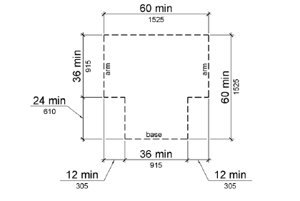
The turning space shall be a T-shaped space within a 60 inch (1525 mm) square minimum with arms and base 36 inches (915 mm) wide minimum. Each arm of the T shall be clear of obstructions 12 inches (305 mm) minimum in each direction and the base shall be clear of obstructions 24 inches (610 mm) minimum. The space shall be permitted to include knee and toe clearance complying with 306 only at the end of either the base or one arm.
View detailed image description
The T shape space is 36 inches (915 mm) wide at the top and stem within a 60 inch by 60 inch (1525 mm by 1525 mm) square.
304.4 Door Swing
Doors shall be permitted to swing into turning spaces.
305 Clear Floor or Ground Space
305.1 General
Clear floor or ground space shall comply with 305.
305.2 Floor or Ground Surfaces
Floor or ground surfaces of a clear floor or ground space shall comply with 302. Changes in level are not permitted.
EXCEPTION: Slopes not steeper than 1:48 shall be permitted.
305.3 Size
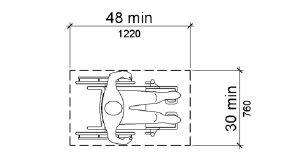
The clear floor or ground space shall be 30 inches (760 mm) minimum by 48 inches (1220 mm) minimum.
View detailed image description
Clear floor or ground space is 30 inches by 48 inches (760 mm by 1220 mm) minimum.
305.4 Knee and Toe Clearance
Unless otherwise specified, clear floor or ground space shall be permitted to include knee and toe clearance complying with 306.
305.5 Position
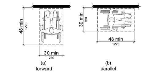
Unless otherwise specified, clear floor or ground space shall be positioned for either forward or parallel approach to an element.
View detailed image description
For a forward approach to an element, a clear floor or ground space, 30 inches by 48 inches (760 mm by 1220 mm) minimum, is shown with the shorter dimension parallel to the wall or element.
For a parallel approach to an element, a clear floor or ground space, 30 inches by 48 inches (760 mm by 1220 mm) minimum, is shown with the longer dimension parallel to the wall or element.
305.6 Approach
One full unobstructed side of the clear floor or ground space shall adjoin an accessible route or adjoin another clear floor or ground space.
305.7 Maneuvering Clearance
Where a clear floor or ground space is located in an alcove or otherwise confined on all or part of three sides, additional maneuvering clearance shall be provided in accordance with 305.7.1 and 305.7.2.
305.7.1 Forward Approach
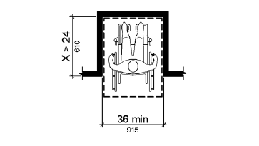
Alcoves shall be 36 inches (915 mm) wide minimum where the depth exceeds 24 inches (610 mm).
View detailed image description
For a forward approach, if the depth of the alcove is greater than 24 inches (610 mm), the clear floor or ground space within the alcove must be 36 inches (915 mm) wide minimum.
305.7.2 Parallel Approach
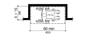
Alcoves shall be 60 inches (1525 mm) wide minimum where the depth exceeds 15 inches (380 mm).
View detailed image description
For a parallel approach, if the depth of the alcove is greater than 15 inches (380 mm), then the length of the clear floor or ground space within the alcove must be 60 inches (1525 mm) minimum.
306 Knee and Toe Clearance
306.1 General
Where space beneath an element is included as part of clear floor or ground space or turning space, the space shall comply with 306. Additional space shall not be prohibited beneath an element but shall not be considered as part of the clear floor or ground space or turning space.
Advisory 306.1 General. Clearances are measured in relation to the usable clear floor space, not necessarily to the vertical support for an element. When determining clearance under an object for required turning or maneuvering space, care should be taken to ensure the space is clear of any obstructions.
306.2 Toe Clearance
306.2.1 General
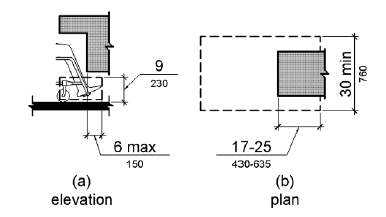
Space under an element between the finish floor or ground and 9 inches (230 mm) above the finish floor or ground shall be considered toe clearance and shall comply with 306.2.
306.2.2 Maximum Depth
Toe clearance shall extend 25 inches (635 mm) maximum under an element.
306.2.3 Minimum Required Depth
Where toe clearance is required at an element as part of a clear floor space, the toe clearance shall extend 17 inches (430 mm) minimum under the element.
306.2.4 Additional Clearance
Space extending greater than 6 inches (150 mm) beyond the available knee clearance at 9 inches (230 mm) above the finish floor or ground shall not be considered toe clearance.
306.2.5 Width
Toe clearance shall be 30 inches (760 mm) wide minimum.
View detailed image description
Figure 306.2(a) Toe Clearance: Elevation. Toes of a person in a wheelchair are shown extending for a maximum depth of 6 inches (150 mm) under an object that is 9 inches (230 mm) high minimum.
Figure 306.2(b) Toe Clearance: Plan. Toe clearance at an element, as part of clear floor space, shall extend 17 to 25 inches (430 to 635 mm) under the element. The clear floor space is 30 inches (760 mm) wide minimum.
306.3 Knee Clearance
306.3.1 General
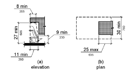
Space under an element between 9 inches (230 mm) and 27 inches (685 mm) above the finish floor or ground shall be considered knee clearance and shall comply with 306.3.
306.3.2 Maximum Depth
Knee clearance shall extend 25 inches (635 mm) maximum under an element at 9 inches (230 mm) above the finish floor or ground.
306.3.3 Minimum Required Depth
Where knee clearance is required under an element as part of a clear floor space, the knee clearance shall be 11 inches (280 mm) deep minimum at 9 inches (230 mm) above the finish floor or ground, and 8 inches (205 mm) deep minimum at 27 inches (685 mm) above the finish floor or ground.
306.3.4 Clearance Reduction
Between 9 inches (230 mm) and 27 inches (685 mm) above the finish floor or ground, the knee clearance shall be permitted to reduce at a rate of 1 inch (25 mm) in depth for each 6 inches (150 mm) in height.
306.3.5 Width
Knee clearance shall be 30 inches (760 mm) wide minimum.
View detailed image description
Figure 306.3(a) Knee Clearance: Elevation. Knee clearance is 27 inches (685 mm) high minimum above the floor or ground for a minimum depth of 8 inches (205 mm), measured from the leading edge of the element. The vertical clearance decreases beyond this depth to a height of 9 inches (230 mm) minimum at depth of 11 inches (280 mm) minimum measured from the leading edge of the element.
Figure 306.3(b) Knee Clearance: Plan. Combined knee and toe clearance can extend 25 inches (635 mm) maximum under an element.
307 Protruding Objects
307.1 General
Protruding objects shall comply with 307.
307.2 Protrusion Limits
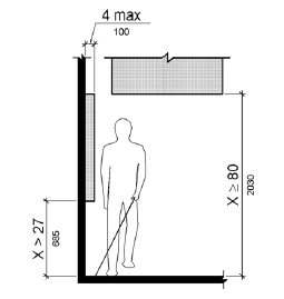
Objects with leading edges more than 27 inches (685 mm) and not more than 80 inches (2030 mm) above the finish floor or ground shall protrude 4 inches (100 mm) maximum horizontally into the circulation path.
EXCEPTION: Handrails shall be permitted to protrude 4½ inches (115 mm) maximum.
Advisory 307.2 Protrusion Limits. When a cane is used and the element is in the detectable range, it gives a person sufficient time to detect the element with the cane before there is body contact. Elements located on circulation paths, including operable elements, must comply with requirements for protruding objects. For example, awnings and their supporting structures cannot reduce the minimum required vertical clearance. Similarly, casement windows, when open, cannot encroach more than 4 inches (100 mm) into circulation paths above 27 inches (685 mm).
View detailed image description
A frontal view shows a person using a cane walking along a wall. A wall-mounted object more than 27 inches (685 mm) from the floor protrudes no more than 4 inches (100 mm) from the wall surface. An object overhead provides vertical clearance that is greater than 80 inches (2030 mm).
307.3 Post-Mounted Objects
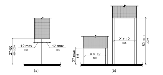
Free-standing objects mounted on posts or pylons shall overhang circulation paths 12 inches (305 mm) maximum when located 27 inches (685 mm) minimum and 80 inches (2030 mm) maximum above the finish floor or ground. Where a sign or other obstruction is mounted between posts or pylons and the clear distance between the posts or pylons is greater than 12 inches (305 mm), the lowest edge of such sign or obstruction shall be 27 inches (685 mm) maximum or 80 inches (2030 mm) minimum above the finish floor or ground.
EXCEPTION: The sloping portions of handrails serving stairs and ramps shall not be required to comply with 307.3.
View detailed image description
Elevation drawing (a) shows an object mounted more than 27 inches (685 mm) high on a post. The object protrudes 12 inches (305 mm) maximum from the post on both sides.
Elevation (b) shows signs or other obstructions mounted between posts or pylons. One object has its lowest edge mounted 27 inches (685 mm) high maximum between posts that are more than 12 inches apart. Another object is mounted with its lowest edge 80 inches (2030 mm) high minimum between posts that are more than 12 inches apart.
307.4 Vertical Clearance
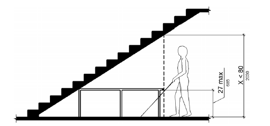
Vertical clearance shall be 80 inches (2030 mm) high minimum. Guardrails or other barriers shall be provided where the vertical clearance is less than 80 inches (2030 mm) high. The leading edge of such guardrail or barrier shall be located 27 inches (685 mm) maximum above the finish floor or ground.
EXCEPTION: Door closers and door stops shall be permitted to be 78 inches (1980 mm) minimum above the finish floor or ground.
View detailed image description
A person using a long cane is shown approaching the sloped underside of a staircase. A portion of the area below the stairs in front of the person has a vertical clearance less than 80 inches (2030 mm). A railing 27 inches (685 mm) high maximum separates this space from the areas where a vertical clearance at or above 80 inches (2030 mm) is maintained.
307.5 Required Clear Width
Protruding objects shall not reduce the clear width required for accessible routes.
308 Reach Ranges
308.1 General
Reach ranges shall comply with 308.
Advisory 308.1 General. The following table provides guidance on reach ranges for children according to age where building elements such as coat hooks, lockers, or operable parts are designed for use primarily by children. These dimensions apply to either forward or side reaches. Accessible elements and operable parts designed for adult use or children over age 12 can be located outside these ranges but must be within the adult reach ranges required by 308.
| Forward or Side Reach | Ages 3 and 4 | Ages 5 through 8 | Ages 9 through 12 |
|---|---|---|---|
| High (maximum) | 36 in (915 mm) | 40 in (1015 mm) | 44 in (1120 mm) |
| Low (minimum) | 20 in (510 mm) | 18 in (455 mm) | 16 in (405 mm) |
308.2 Forward Reach
308.2.1 Unobstructed
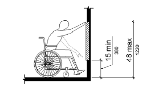
Where a forward reach is unobstructed, the high forward reach shall be 48 inches (1220 mm) maximum and the low forward reach shall be 15 inches (380 mm) minimum above the finish floor or ground.
View detailed image description
A side view is shown of a person using a wheelchair reaching toward a wall. The lowest vertical reach point is 15 inches (380 mm) minimum and the highest is 48 inches (1220 mm) maximum.
308.2.2 Obstructed High Reach
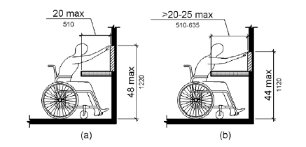
Where a high forward reach is over an obstruction, the clear floor space shall extend beneath the element for a distance not less than the required reach depth over the obstruction. The high forward reach shall be 48 inches (1220 mm) maximum where the reach depth is 20 inches (510 mm) maximum. Where the reach depth exceeds 20 inches (510 mm), the high forward reach shall be 44 inches (1120 mm) maximum and the reach depth shall be 25 inches (635 mm) maximum.
View detailed image description
Figure (a) shows a person seated in a wheelchair reaching a point on a wall above a protrusion, such as a wall-mounted counter, which is 20 inches (510 mm) deep maximum. The maximum reach height is 48 inches (1220 mm).
In figure (b), the obstruction is more than 20 inches (510 mm) deep, with 25 inches (635 mm) the maximum depth. The maximum reach height is 44 inches (1120 mm).
308.3 Side Reach
308.3.1 Unobstructed
Where a clear floor or ground space allows a parallel approach to an element and the side reach is unobstructed, the high side reach shall be 48 inches (1220 mm) maximum and the low side reach shall be 15 inches (380 mm) minimum above the finish floor or ground.
EXCEPTIONS:
- An obstruction shall be permitted between the clear floor or ground space and the element where the depth of the obstruction is 10 inches (255 mm) maximum.
- Operable parts of fuel dispensers shall be permitted to be 54 inches (1370 mm) maximum measured from the surface of the vehicular way where fuel dispensers are installed on existing curbs.
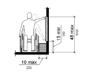
View detailed image description
The drawing shows a frontal view of a person using a wheelchair making a side reach to a wall. The depth of reach is 10 inches (255 mm) maximum. The vertical reach range is 15 inches (380 mm) minimum to 48 inches (1220 mm) maximum.
308.3.2 Obstructed High Reach
Where a clear floor or ground space allows a parallel approach to an element and the high side reach is over an obstruction, the height of the obstruction shall be 34 inches (865 mm) maximum and the depth of the obstruction shall be 24 inches (610 mm) maximum. The high side reach shall be 48 inches (1220 mm) maximum for a reach depth of 10 inches (255 mm) maximum. Where the reach depth exceeds 10 inches (255 mm), the high side reach shall be 46 inches (1170 mm) maximum for a reach depth of 24 inches (610 mm) maximum.
EXCEPTIONS:
- The top of washing machines and clothes dryers shall be permitted to be 36 inches (915 mm) maximum above the finish floor.
- Operable parts of fuel dispensers shall be permitted to be 54 inches (1370 mm) maximum measured from the surface of the vehicular way where fuel dispensers are installed on existing curbs.

View detailed image description
In figure (a), a person seated in a wheelchair is shown reaching to the side over an obstruction 10 inches (510 mm) deep maximum and 34 inches (865 mm) high maximum. The maximum reach height is 48 inches (1220 mm).
In figure (b) the obstruction depth is 10 inches to 24 inches maximum (255 to 610 mm) and 34 inches (865 mm) high maximum. The maximum reach height is 46 inches (1170 mm).
309 Operable Parts
309.1 General
Operable parts shall comply with 309.
309.2 Clear Floor Space
A clear floor or ground space complying with 305 shall be provided.
309.3 Height
Operable parts shall be placed within one or more of the reach ranges specified in 308.
309.4 Operation
Operable parts shall be operable with one hand and shall not require tight grasping, pinching, or twisting of the wrist. The force required to activate operable parts shall be 5 pounds (22.2 N) maximum.
EXCEPTION: Gas pump nozzles shall not be required to provide operable parts that have an activating force of 5 pounds (22.2 N) maximum.