
601 General
601.1 Scope. The provisions of Chapter 6 shall apply where required by Chapter 2 or where referenced by a requirement in this document.
602 Drinking Fountains
602.1 General. Drinking fountains shall comply with 307 and 602.
602.2 Clear Floor Space. Units shall have a clear floor or ground space complying with 305 positioned for a forward approach and centered on the unit. Knee and toe clearance complying with 306 shall be provided.
EXCEPTION: A parallel approach complying with 305 shall be permitted at units for children's use where the spout is 30 inches (760 mm) maximum above the finish floor or ground and is 3 1/2 inches (90 mm) maximum from the front edge of the unit, including bumpers.
602.3 Operable Parts. Operable parts shall comply with 309.
602.4 Spout Height. Spout outlets shall be 36 inches (915 mm) maximum above the finish floor or ground.
602.5 Spout Location. The spout shall be located 15 inches (380 mm) minimum from the vertical support and 5 inches (125 mm) maximum from the front edge of the unit, including bumpers.
602.6 Water Flow. The spout shall provide a flow of water 4 inches (100 mm) high minimum and shall be located 5 inches (125 mm) maximum from the front of the unit. The angle of the water stream shall be measured horizontally relative to the front face of the unit. Where spouts are located less than 3 inches (75 mm) of the front of the unit, the angle of the water stream shall be 30 degrees maximum. Where spouts are located between 3 inches (75 mm) and 5 inches (125 mm) maximum from the front of the unit, the angle of the water stream shall be 15 degrees maximum.
Advisory 602.6 Water Flow. The purpose of requiring the drinking fountain spout to produce a flow of water 4 inches (100 mm) high minimum is so that a cup can be inserted under the flow of water to provide a drink of water for an individual who, because of a disability, would otherwise be incapable of using the drinking fountain.
602.7 Drinking Fountains for Standing Persons. Spout outlets of drinking fountains for standing persons shall be 38 inches (965 mm) minimum and 43 inches (1090 mm) maximum above the finish floor or ground.
603 Toilet and Bathing Rooms
603.1 General. Toilet and bathing rooms shall comply with 603.
603.2 Clearances. Clearances shall comply with 603.2.
603.2.1 Turning Space. Turning space complying with 304 shall be provided within the room.
603.2.2 Overlap. Required clear floor spaces, clearance at fixtures, and turning space shall be permitted to overlap.
603.2.3 Door Swing. Doors shall not swing into the clear floor space or clearance required for any fixture. Doors shall be permitted to swing into the required turning space.
EXCEPTIONS: 1. Doors to a toilet room or bathing room for a single occupant accessed only through a private office and not for common use or public use shall be permitted to swing into the clear floor space or clearance provided the swing of the door can be reversed to comply with 603.2.3.
2. Where the toilet room or bathing room is for individual use and a clear floor space complying with 305.3 is provided within the room beyond the arc of the door swing, doors shall be permitted to swing into the clear floor space or clearance required for any fixture.
Advisory 603.2.3 Door Swing Exception 1. At the time the door is installed, and if the door swing is reversed in the future, the door must meet all the requirements specified in 404. Additionally, the door swing cannot reduce the required width of an accessible route. Also, avoid violating other building or life safety codes when the door swing is reversed.
603.3 Mirrors. Mirrors located above lavatories or countertops shall be installed with the bottom edge of the reflecting surface 40 inches (1015 mm) maximum above the finish floor or ground. Mirrors not located above lavatories or countertops shall be installed with the bottom edge of the reflecting surface 35 inches (890 mm) maximum above the finish floor or ground.
Advisory 603.3 Mirrors. A single full-length mirror can accommodate a greater number of people, including children. In order for mirrors to be usable by people who are ambulatory and people who use wheelchairs, the top edge of mirrors should be 74 inches (1880 mm) minimum from the floor or ground.
603.4 Coat Hooks and Shelves. Coat hooks shall be located within one of the reach ranges specified in 308. Shelves shall be located 40 inches (1015 mm) minimum and 48 inches (1220 mm) maximum above the finish floor.
604 Water Closets and Toilet Compartments
604.1 General. Water closets and toilet compartments shall comply with 604.2 through 604.8.
EXCEPTION: Water closets and toilet compartments for children's use shall be permitted to comply with 604.9.
604.2 Location. The water closet shall be positioned with a wall or partition to the rear and to one side. The centerline of the water closet shall be 16 inches (405 mm) minimum to 18 inches (455 mm) maximum from the side wall or partition, except that the water closet shall be 17 inches (430 mm) minimum and 19 inches (485 mm) maximum from the side wall or partition in the ambulatory accessible toilet compartment specified in 604.8.2. Water closets shall be arranged for a left-hand or right-hand approach.
604.3 Clearance. Clearances around water closets and in toilet compartments shall comply with 604.3.
604.3.1 Size. Clearance around a water closet shall be 60 inches (1525 mm) minimum measured perpendicular from the side wall and 56 inches (1420 mm) minimum measured perpendicular from the rear wall.
604.3.2 Overlap. The required clearance around the water closet shall be permitted to overlap the water closet, associated grab bars, dispensers, sanitary napkin disposal units, coat hooks, shelves, accessible routes, clear floor space and clearances required at other fixtures, and the turning space. No other fixtures or obstructions shall be located within the required water closet clearance.
EXCEPTION: In residential dwelling units, a lavatory complying with 606 shall be permitted on the rear wall 18 inches (455 mm) minimum from the water closet centerline where the clearance at the water closet is 66 inches (1675 mm) minimum measured perpendicular from the rear wall.
Advisory 604.3.2 Overlap. When the door to the toilet room is placed directly in front of the water closet, the water closet cannot overlap the required maneuvering clearance for the door inside the room.
604.4 Seats. The seat height of a water closet above the finish floor shall be 17 inches (430 mm) minimum and 19 inches (485 mm) maximum measured to the top of the seat. Seats shall not be sprung to return to a lifted position.
EXCEPTIONS: 1. A water closet in a toilet room for a single occupant accessed only through a private office and not for common use or public use shall not be required to comply with 604.4.
2. In residential dwelling units, the height of water closets shall be permitted to be 15 inches (380 mm) minimum and 19 inches (485 mm) maximum above the finish floor measured to the top of the seat.
604.5 Grab Bars. Grab bars for water closets shall comply with 609. Grab bars shall be provided on the side wall closest to the water closet and on the rear wall.
EXCEPTIONS: 1. Grab bars shall not be required to be installed in a toilet room for a single occupant accessed only through a private office and not for common use or public use provided that reinforcement has been installed in walls and located so as to permit the installation of grab bars complying with 604.5.
2. In residential dwelling units, other than emergency transportable housing units required to provide mobility features complying with 809.2, grab bars shall not be required to be installed in toilet or bathrooms provided that reinforcement has been installed in walls and located so as to permit the installation of grab bars complying with 604.5.
3. In detention or correction facilities, grab bars shall not be required to be installed in housing or holding cells that are specially designed without protrusions for purposes of suicide prevention.
Advisory 604.5 Grab Bars Exception 2. Reinforcement must be sufficient to permit the installation of rear and side wall grab bars that fully meet all accessibility requirements including, but not limited to, required length, installation height, and structural strength.
604.5.1 Side Wall. The side wall grab bar shall be 42 inches (1065 mm) long minimum, located 12 inches (305 mm) maximum from the rear wall and extending 54 inches (1370 mm) minimum from the rear wall.
604.5.2 Rear Wall. The rear wall grab bar shall be 36 inches (915 mm) long minimum and extend from the centerline of the water closet 12 inches (305 mm) minimum on one side and 24 inches (610 mm) minimum on the other side.
EXCEPTIONS: 1. The rear grab bar shall be permitted to be 24 inches (610 mm) long minimum, centered on the water closet, where wall space does not permit a length of 36 inches (915 mm) minimum due to the location of a recessed fixture adjacent to the water closet.
2. Where an administrative authority requires flush controls for flush valves to be located in a position that conflicts with the location of the rear grab bar, then the rear grab bar shall be permitted to be split or shifted to the open side of the toilet area.
604.6 Flush Controls. Flush controls shall be hand operated or automatic. Hand operated flush controls shall comply with 309. Flush controls shall be located on the open side of the water closet except in ambulatory accessible compartments complying with 604.8.2.
Advisory 604.6 Flush Controls. If plumbing valves are located directly behind the toilet seat, flush valves and related plumbing can cause injury or imbalance when a person leans back against them. To prevent causing injury or imbalance, the plumbing can be located behind walls or to the side of the toilet; or if approved by the local authority having jurisdiction, provide a toilet seat lid.
604.7 Dispensers. Toilet paper dispensers shall comply with 309.4 and shall be 7 inches (180 mm) minimum and 9 inches (230 mm) maximum in front of the water closet measured to the centerline of the dispenser. The outlet of the dispenser shall be 15 inches (380 mm) minimum and 48 inches (1220 mm) maximum above the finish floor and shall not be located behind grab bars. Dispensers shall not be of a type that controls delivery or that does not allow continuous paper flow.
Advisory 604.7 Dispensers. If toilet paper dispensers are installed above the side wall grab bar, the outlet of the toilet paper dispenser must be 48 inches (1220 mm) maximum above the finish floor and the top of the gripping surface of the grab bar must be 33 inches (840 mm) minimum and 36 inches (915 mm) maximum above the finish floor.
604.8 Toilet Compartments. Wheelchair accessible toilet compartments shall meet the requirements of 604.8.1 and 604.8.3. Compartments containing more than one plumbing fixture shall comply with 603. Ambulatory accessible compartments shall comply with 604.8.2 and 604.8.3.
604.8.1 Wheelchair Accessible Compartments. Wheelchair accessible compartments shall comply with 604.8.1.
604.8.1.1 Size. Wheelchair accessible compartments shall be 60 inches (1525 mm) wide minimum measured perpendicular to the side wall, and 56 inches (1420 mm) deep minimum for wall hung water closets and 59 inches (1500 mm) deep minimum for floor mounted water closets measured perpendicular to the rear wall. Wheelchair accessible compartments for children's use shall be 60 inches (1525 mm) wide minimum measured perpendicular to the side wall, and 59 inches (1500 mm) deep minimum for wall hung and floor mounted water closets measured perpendicular to the rear wall.
Advisory 604.8.1.1 Size. The minimum space required in toilet compartments is provided so that a person using a wheelchair can maneuver into position at the water closet. This space cannot be obstructed by baby changing tables or other fixtures or conveniences, except as specified at 604.3.2 (Overlap). If toilet compartments are to be used to house fixtures other than those associated with the water closet, they must be designed to exceed the minimum space requirements. Convenience fixtures such as baby changing tables must also be accessible to people with disabilities as well as to other users. Toilet compartments that are designed to meet, and not exceed, the minimum space requirements may not provide adequate space for maneuvering into position at a baby changing table.
604.8.1.2 Doors. Toilet compartment doors, including door hardware, shall comply with 404 except that if the approach is to the latch side of the compartment door, clearance between the door side of the compartment and any obstruction shall be 42 inches (1065 mm) minimum. Doors shall be located in the front partition or in the side wall or partition farthest from the water closet. Where located in the front partition, the door opening shall be 4 inches (100 mm) maximum from the side wall or partition farthest from the water closet. Where located in the side wall or partition, the door opening shall be 4 inches (100 mm) maximum from the front partition. The door shall be self-closing. A door pull complying with 404.2.7 shall be placed on both sides of the door near the latch. Toilet compartment doors shall not swing into the minimum required compartment area.
604.8.1.3 Approach. Compartments shall be arranged for left-hand or right-hand approach to the water closet.
604.8.1.4 Toe Clearance. The front partition and at least one side partition shall provide a toe clearance of 9 inches (230 mm) minimum above the finish floor and 6 inches (150 mm) deep minimum beyond the compartment-side face of the partition, exclusive of partition support members. Compartments for children's use shall provide a toe clearance of 12 inches (305 mm) minimum above the finish floor.
EXCEPTION: Toe clearance at the front partition is not required in a compartment greater than 62 inches (1575 mm) deep with a wall-hung water closet or 65 inches (1650 mm) deep with a floor-mounted water closet. Toe clearance at the side partition is not required in a compartment greater than 66 inches (1675 mm) wide. Toe clearance at the front partition is not required in a compartment for children's use that is greater than 65 inches (1650 mm) deep.
604.8.1.5 Grab Bars. Grab bars shall comply with 609. A side-wall grab bar complying with 604.5.1 shall be provided and shall be located on the wall closest to the water closet. In addition, a rear-wall grab bar complying with 604.5.2 shall be provided.
604.8.2 Ambulatory Accessible Compartments. Ambulatory accessible compartments shall comply with 604.8.2.
604.8.2.1 Size. Ambulatory accessible compartments shall have a depth of 60 inches (1525 mm) minimum and a width of 35 inches (890 mm) minimum and 37 inches (940 mm) maximum.
604.8.2.2 Doors. Toilet compartment doors, including door hardware, shall comply with 404, except that if the approach is to the latch side of the compartment door, clearance between the door side of the compartment and any obstruction shall be 42 inches (1065 mm) minimum. The door shall be self-closing. A door pull complying with 404.2.7 shall be placed on both sides of the door near the latch. Toilet compartment doors shall not swing into the minimum required compartment area.
604.8.2.3 Grab Bars. Grab bars shall comply with 609. A side-wall grab bar complying with 604.5.1 shall be provided on both sides of the compartment.
604.8.3 Coat Hooks and Shelves. Coat hooks shall be located within one of the reach ranges specified in 308. Shelves shall be located 40 inches (1015 mm) minimum and 48 inches (1220 mm) maximum above the finish floor.
604.9 Water Closets and Toilet Compartments for Children's Use. Water closets and toilet compartments for children's use shall comply with 604.9.
Advisory 604.9 Water Closets and Toilet Compartments for Children's Use. The requirements in 604.9 are to be followed where the exception for children's water closets in 604.1 is used. The following table provides additional guidance in applying the specifications for water closets for children according to the age group served and reflects the differences in the size, stature, and reach ranges of children ages 3 through 12. The specifications chosen should correspond to the age of the primary user group. The specifications of one age group should be applied consistently in the installation of a water closet and related elements.
| Ages 3 and 4 | Ages 5 through 8 | Ages 9 through 12 | |
|---|---|---|---|
| Water Closet Centerline | 12 inches (305 mm) |
12 to 15 inches (305 to 380 mm) |
15 to 18 inches (380 to 455 mm) |
| Toilet Seat Height | 11 to 12 inches (280 to 305 mm) |
12 to 15 inches (305 to 380 mm) |
15 to 17 inches (380 to 430 mm) |
| Grab Bar Height | 18 to 20 inches (455 to 510 mm) |
20 to 25 inches (510 to 635 mm) |
25 to 27 inches (635 to 685 mm) |
| Dispenser Height | 14 inches (355 mm) |
14 to 17 inches (355 to 430 mm) |
17 to 19 inches (430 to 485 mm) |
604.9.1 Location. The water closet shall be located with a wall or partition to the rear and to one side. The centerline of the water closet shall be 12 inches (305 mm) minimum and 18 inches (455 mm) maximum from the side wall or partition, except that the water closet shall be 17 inches (430 mm) minimum and 19 inches (485 mm) maximum from the side wall or partition in the ambulatory accessible toilet compartment specified in 604.8.2. Compartments shall be arranged for left-hand or right-hand approach to the water closet.
604.9.2 Clearance. Clearance around a water closet shall comply with 604.3.
604.9.3 Height. The height of water closets shall be 11 inches (280 mm) minimum and 17 inches (430 mm) maximum measured to the top of the seat. Seats shall not be sprung to return to a lifted position.
604.9.4 Grab Bars. Grab bars for water closets shall comply with 604.5.
604.9.5 Flush Controls. Flush controls shall be hand operated or automatic. Hand operated flush controls shall comply with 309.2 and 309.4 and shall be installed 36 inches (915 mm) maximum above the finish floor. Flush controls shall be located on the open side of the water closet except in ambulatory accessible compartments complying with 604.8.2.
604.9.6 Dispensers. Toilet paper dispensers shall comply with 309.4 and shall be 7 inches (180 mm) minimum and 9 inches (230 mm) maximum in front of the water closet measured to the centerline of the dispenser. The outlet of the dispenser shall be 14 inches (355 mm) minimum and 19 inches (485 mm) maximum above the finish floor. There shall be a clearance of 1 1/2 inches (38 mm) minimum below the grab bar. Dispensers shall not be of a type that controls delivery or that does not allow continuous paper flow.
604.9.7 Toilet Compartments. Toilet compartments shall comply with 604.8.
605 Urinals
605.1 General. Urinals shall comply with 605.
Advisory 605.1 General. Stall-type urinals provide greater accessibility for a broader range of persons, including people of short stature.
605.2 Height and Depth. Urinals shall be the stall-type or the wall-hung type with the rim 17 inches (430 mm) maximum above the finish floor or ground. Urinals shall be 13 1/2 inches (345 mm) deep minimum measured from the outer face of the urinal rim to the back of the fixture.
605.3 Clear Floor Space. A clear floor or ground space complying with 305 positioned for forward approach shall be provided.
605.4 Flush Controls. Flush controls shall be hand operated or automatic. Hand operated flush controls shall comply with 309.
606 Lavatories and Sinks
606.1 General. Lavatories and sinks shall comply with 606.
Advisory 606.1 General. If soap and towel dispensers are provided, they must be located within the reach ranges specified in 308. Locate soap and towel dispensers so that they are conveniently usable by a person at the accessible lavatory.
606.2 Clear Floor Space. A clear floor space complying with 305, positioned for a forward approach, and knee and toe clearance complying with 306 shall be provided.
EXCEPTIONS: 1. A parallel approach complying with 305 shall be permitted to a kitchen sink in a space where a cook top or conventional range is not provided and to wet bars.
2. A lavatory in a toilet room or bathing facility for a single occupant accessed only through a private office and not for common use or public use shall not be required to provide knee and toe clearance complying with 306.
3. In residential dwelling units, other than emergency transportable housing units required to provide mobility features complying with 809.2, cabinetry shall be permitted under lavatories and kitchen sinks provided that all of the following conditions are met:
- the cabinetry can be removed without removal or replacement of the fixture;
- the finish floor extends under the cabinetry; and
- the walls behind and surrounding the cabinetry are finished.
4. A knee clearance of 24 inches (610 mm) minimum above the finish floor or ground shall be permitted at lavatories and sinks used primarily by children 6 through 12 years where the rim or counter surface is 31 inches (785 mm) maximum above the finish floor or ground.
5. A parallel approach complying with 305 shall be permitted to lavatories and sinks used primarily by children 5 years and younger.
6. The dip of the overflow shall not be considered in determining knee and toe clearances.
7. No more than one bowl of a multi-bowl sink shall be required to provide knee and toe clearance complying with 306.
606.3 Height. Lavatories and sinks shall be installed with the front of the higher of the rim or counter surface 34 inches (865 mm) maximum above the finish floor or ground.
EXCEPTIONS: 1. A lavatory in a toilet or bathing facility for a single occupant accessed only through a private office and not for common use or public use shall not be required to comply with 606.3.
2. In residential dwelling unit kitchens, sinks that are adjustable to variable heights, 29 inches (735 mm) minimum and 36 inches (915 mm) maximum, shall be permitted where rough-in plumbing permits connections of supply and drain pipes for sinks mounted at the height of 29 inches (735 mm).
606.4 Faucets and Water Spray Units. Controls for faucets shall comply with 309. Hand-operated metering faucets shall remain open for 10 seconds minimum. A water spray unit shall be provided at the kitchen sink in emergency transportable housing units required to provide mobility features complying with 809.2.
606.5 Exposed Pipes and Surfaces. Water supply and drain pipes under lavatories and sinks shall be insulated or otherwise configured to protect against contact. There shall be no sharp or abrasive surfaces under lavatories and sinks.
607 Bathtubs
607.1 General. Bathtubs shall comply with 607.
607.2 Clearance. Clearance in front of bathtubs shall extend the length of the bathtub and shall be 30 inches (760 mm) wide minimum. A lavatory complying with 606 shall be permitted at the control end of the clearance. Where a permanent seat is provided at the head end of the bathtub, the clearance shall extend 12 inches (305 mm) minimum beyond the wall at the head end of the bathtub.
607.3 Seat. A permanent seat at the head end of the bathtub or a removable in-tub seat shall be provided. Seats shall comply with 610.
607.4 Grab Bars. Grab bars for bathtubs shall comply with 609 and shall be provided in accordance with 607.4.1 or 607.4.2.
EXCEPTIONS: 1. Grab bars shall not be required to be installed in a bathtub located in a bathing facility for a single occupant accessed only through a private office and not for common use or public use provided that reinforcement has been installed in walls and located so as to permit the installation of grab bars complying with 607.4.
2. In residential dwelling units, other than emergency transportable housing units required to provide mobility features complying with 809.2, grab bars shall not be required to be installed in bathtubs located in bathing facilities provided that reinforcement has been installed in walls and located so as to permit the installation of grab bars complying with 607.4.
607.4.1 Bathtubs With Permanent Seats. For bathtubs with permanent seats, grab bars shall be provided in accordance with 607.4.1.
607.4.1.1 Back Wall. Two grab bars shall be installed on the back wall, one located in accordance with 609.4 and the other located 8 inches (205 mm) minimum and 10 inches (255 mm) maximum above the rim of the bathtub. Each grab bar shall be installed 15 inches (380 mm) maximum from the head end wall and 12 inches (305 mm) maximum from the control end wall.
607.4.1.2 Control End Wall. A grab bar 24 inches (610 mm) long minimum shall be installed on the control end wall at the front edge of the bathtub.
607.4.2 Bathtubs Without Permanent Seats. For bathtubs without permanent seats, grab bars shall comply with 607.4.2.
607.4.2.1 Back Wall. Two grab bars shall be installed on the back wall, one located in accordance with 609.4 and other located 8 inches (205 mm) minimum and 10 inches (255 mm) maximum above the rim of the bathtub. Each grab bar shall be 24 inches (610 mm) long minimum and shall be installed 24 inches (610 mm) maximum from the head end wall and 12 inches (305 mm) maximum from the control end wall.
607.4.2.2 Control End Wall. A grab bar 24 inches (610 mm) long minimum shall be installed on the control end wall at the front edge of the bathtub.
607.4.2.3 Head End Wall. A grab bar 12 inches (305 mm) long minimum shall be installed on the head end wall at the front edge of the bathtub.
607.5 Controls. Controls, other than drain stoppers, shall be located on an end wall. Controls shall be between the bathtub rim and grab bar, and between the open side of the bathtub and the centerline of the width of the bathtub. Controls shall comply with 309.4.
607.6 Shower Spray Unit and Water. A shower spray unit with a hose 59 inches (1500 mm) long minimum that can be used both as a fixed-position shower head and as a hand-held shower shall be provided. The shower spray unit shall have an on/off control with a non-positive shut-off. If an adjustable-height shower head on a vertical bar is used, the bar shall be installed so as not to obstruct the use of grab bars. Bathtub shower spray units shall deliver water that is 120°F (49°C) maximum.
Advisory 607.6 Shower Spray Unit and Water. Ensure that hand-held shower spray units are capable of delivering water pressure substantially equivalent to fixed shower heads.
607.7 Bathtub Enclosures. Enclosures for bathtubs shall not obstruct controls, faucets, shower and spray units or obstruct transfer from wheelchairs onto bathtub seats or into bathtubs. Enclosures on bathtubs shall not have tracks installed on the rim of the open face of the bathtub.
608 Shower Compartments
608.1 General. Shower compartments shall comply with 608.
Advisory 608.1 General. Shower stalls that are 60 inches (1525 mm) wide and have no curb may increase the usability of a bathroom because the shower area provides additional maneuvering space.
608.2 Size and Clearances for Shower Compartments. Shower compartments shall have sizes and clearances complying with 608.2.
608.2.1 Transfer Type Shower Compartments. Transfer type shower compartments shall be 36 inches (915 mm) by 36 inches (915 mm) clear inside dimensions measured at the center points of opposing sides and shall have a 36 inch (915 mm) wide minimum entry on the face of the shower compartment. Clearance of 36 inches (915 mm) wide minimum by 48 inches (1220 mm) long minimum measured from the control wall shall be provided.
608.2.2 Standard Roll-In Type Shower Compartments. Standard roll-in type shower compartments shall be 30 inches (760 mm) wide minimum by 60 inches (1525 mm) deep minimum clear inside dimensions measured at center points of opposing sides and shall have a 60 inches (1525 mm) wide minimum entry on the face of the shower compartment.
608.2.2.1 Clearance. A 30 inch (760 mm) wide minimum by 60 inch (1525 mm) long minimum clearance shall be provided adjacent to the open face of the shower compartment.
EXCEPTION: A lavatory complying with 606 shall be permitted on one 30 inch (760 mm) wide minimum side of the clearance provided that it is not on the side of the clearance adjacent to the controls or, where provided, not on the side of the clearance adjacent to the shower seat.
608.2.3 Alternate Roll-In Type Shower Compartments. Alternate roll-in type shower compartments shall be 36 inches (915 mm) wide and 60 inches (1525 mm) deep minimum clear inside dimensions measured at center points of opposing sides. A 36 inch (915 mm) wide minimum entry shall be provided at one end of the long side of the compartment.
608.3 Grab Bars. Grab bars shall comply with 609 and shall be provided in accordance with 608.3. Where multiple grab bars are used, required horizontal grab bars shall be installed at the same height above the finish floor.
EXCEPTIONS: 1. Grab bars shall not be required to be installed in a shower located in a bathing facility for a single occupant accessed only through a private office, and not for common use or public use provided that reinforcement has been installed in walls and located so as to permit the installation of grab bars complying with 608.3.
2. In residential dwelling units, other than emergency transportable housing units required to provide mobility features complying with 809.2, grab bars shall not be required to be installed in showers located in bathing facilities provided that reinforcement has been installed in walls and located so as to permit the installation of grab bars complying with 608.3.
608.3.1 Transfer Type Shower Compartments. In transfer type compartments, grab bars shall be provided across the control wall and back wall to a point 18 inches (455 mm) from the control wall.
608.3.2 Standard Roll-In Type Shower Compartments. Where a seat is provided in standard roll-in type shower compartments, grab bars shall be provided on the back wall and the side wall opposite the seat. Grab bars shall not be provided above the seat. Where a seat is not provided in standard roll-in type shower compartments, grab bars shall be provided on three walls. Grab bars shall be installed 6 inches (150 mm) maximum from adjacent walls.
608.3.3 Alternate Roll-In Type Shower Compartments. In alternate roll-in type shower compartments, grab bars shall be provided on the back wall and the side wall farthest from the compartment entry. Grab bars shall not be provided above the seat. Grab bars shall be installed 6 inches (150 mm) maximum from adjacent walls.
608.4 Seats. A folding or non-folding seat shall be provided in transfer type shower compartments. A folding seat shall be provided in roll-in type showers required in transient lodging guest rooms with mobility features complying with 806.2 and in roll-in type showers provided in emergency transportable housing units required to provide mobility features complying with 809.2. Seats shall comply with 610.
EXCEPTION: In residential dwelling units, other than emergency transportable housing units, seats shall not be required in transfer type shower compartments provided that reinforcement has been installed in walls so as to permit the installation of seats complying with 608.4.
608.5 Controls. Controls, faucets, and shower spray units shall comply with 309.4.
608.5.1 Transfer Type Shower Compartments. In transfer type shower compartments, the controls, faucets, and shower spray unit shall be installed on the side wall opposite the seat 38 inches (965 mm) minimum and 48 inches (1220 mm) maximum above the shower floor and shall be located on the control wall 15 inches (380 mm) maximum from the centerline of the seat toward the shower opening.
608.5.2 Standard Roll-In Type Shower Compartments. In standard roll-in type shower compartments, the controls, faucets, and shower spray unit shall be located above the grab bar, but no higher than 48 inches (1220 mm) above the shower floor. Where a seat is provided, the controls, faucets, and shower spray unit shall be installed on the back wall adjacent to the seat wall and shall be located 27 inches (685 mm) maximum from the seat wall.
Advisory 608.5.2 Standard Roll-In Type Shower Compartments. In standard roll-in type showers without seats, the shower head and operable parts can be located on any of the three walls of the shower without adversely affecting accessibility.
608.5.3 Alternate Roll-In Type Shower Compartments. In alternate roll-in type shower compartments, the controls, faucets, and shower spray unit shall be located above the grab bar, but no higher than 48 inches (1220 mm) above the shower floor. Where a seat is provided, the controls, faucets, and shower spray unit shall be located on the side wall adjacent to the seat 27 inches (685 mm) maximum from the side wall behind the seat or shall be located on the back wall opposite the seat 15 inches (380 mm) maximum, left or right, of the centerline of the seat. Where a seat is not provided, the controls, faucets, and shower spray unit shall be installed on the side wall farthest from the compartment entry.
608.6 Shower Spray Unit and Water. A shower spray unit with a hose 59 inches (1500 mm) long minimum that can be used both as a fixed-position shower head and as a hand-held shower shall be provided. The shower spray unit shall have an on/off control with a non-positive shut-off. If an adjustable-height shower head on a vertical bar is used, the bar shall be installed so as not to obstruct the use of grab bars. Shower spray units shall deliver water that is 120°F (49°C) maximum.
EXCEPTION: A fixed shower head located at 48 inches (1220 mm) maximum above the shower finish floor shall be permitted instead of a hand-held spray unit in facilities that are not medical care facilities, long-term care facilities, transient lodging guest rooms, or residential dwelling units.
Advisory 608.6 Shower Spray Unit and Water. Ensure that hand-held shower spray units are capable of delivering water pressure substantially equivalent to fixed shower heads.
608.7 Thresholds. Thresholds in roll-in type shower compartments shall be 1/2 inch (13 mm) high maximum in accordance with 303. In transfer type shower compartments, thresholds 1/2 inch (13 mm) high maximum shall be beveled, rounded, or vertical.
EXCEPTION: A threshold 2 inches (51 mm) high maximum shall be permitted in transfer type shower compartments in existing facilities where provision of a 1/2 inch (13 mm) high threshold would disturb the structural reinforcement of the floor slab.
608.8 Shower Enclosures. Enclosures for shower compartments shall not obstruct controls, faucets, and shower spray units or obstruct transfer from wheelchairs onto shower seats.
609 Grab Bars
609.1 General. Grab bars in toilet facilities and bathing facilities shall comply with 609.
609.2 Cross Section. Grab bars shall have a cross section complying with 609.2.1 or 609.2.2.
609.2.1 Circular Cross Section. Grab bars with circular cross sections shall have an outside diameter of 1 1/4 inches (32 mm) minimum and 2 inches (51 mm) maximum.
609.2.2 Non-Circular Cross Section. Grab bars with non-circular cross sections shall have a cross-section dimension of 2 inches (51 mm) maximum and a perimeter dimension of 4 inches (100 mm) minimum and 4.8 inches (120 mm) maximum.
609.3 Spacing. The space between the wall and the grab bar shall be 1 1/2 inches (38 mm). The space between the grab bar and projecting objects below and at the ends shall be 1 1/2 inches (38 mm) minimum. The space between the grab bar and projecting objects above shall be 12 inches (305 mm) minimum.
EXCEPTION: The space between the grab bars and shower controls, shower fittings, and other grab bars above shall be permitted to be 1 1/2 inches (38 mm) minimum.
609.4 Position of Grab Bars. Grab bars shall be installed in a horizontal position, 33 inches (840 mm) minimum and 36 inches (915 mm) maximum above the finish floor measured to the top of the gripping surface, except that at water closets for children's use complying with 604.9, grab bars shall be installed in a horizontal position 18 inches (455 mm) minimum and 27 inches (685 mm) maximum above the finish floor measured to the top of the gripping surface. The height of the lower grab bar on the back wall of a bathtub shall comply with 607.4.1.1 or 607.4.2.1.
609.5 Surface Hazards. Grab bars and any wall or other surfaces adjacent to grab bars shall be free of sharp or abrasive elements and shall have rounded edges.
609.6 Fittings. Grab bars shall not rotate within their fittings.
609.7 Installation. Grab bars shall be installed in any manner that provides a gripping surface at the specified locations and that does not obstruct the required clear floor space.
609.8 Structural Strength. Allowable stresses shall not be exceeded for materials used when a vertical or horizontal force of 250 pounds (1112 N) is applied at any point on the grab bar, fastener, mounting device, or supporting structure.
610 Seats
610.1 General. Seats in bathtubs and shower compartments shall comply with 610.
610.2 Bathtub Seats. The top of bathtub seats shall be 17 inches (430 mm) minimum and 19 inches (485 mm) maximum above the bathroom finish floor. The depth of a removable in-tub seat shall be 15 inches (380 mm) minimum and 16 inches (405 mm) maximum. The seat shall be capable of secure placement. Permanent seats at the head end of the bathtub shall be 15 inches (380 mm) deep minimum and shall extend from the back wall to or beyond the outer edge of the bathtub.
610.3 Shower Compartment Seats. Where a seat is provided in a standard roll-in shower compartment, it shall be a folding type, shall be installed on the side wall adjacent to the controls, and shall extend from the back wall to a point within 3 inches (75 mm) of the compartment entry. Where a seat is provided in an alternate roll-in type shower compartment, it shall be a folding type, shall be installed on the front wall opposite the back wall, and shall extend from the adjacent side wall to a point within 3 inches (75 mm) of the compartment entry. In transfer-type showers, the seat shall extend from the back wall to a point within 3 inches (75 mm) of the compartment entry. The top of the seat shall be 17 inches (430 mm) minimum and 19 inches (485 mm) maximum above the bathroom finish floor. Seats shall comply with 610.3.1 or 610.3.2.
610.3.1 Rectangular Seats. The rear edge of a rectangular seat shall be 2 1/2 inches (64 mm) maximum and the front edge 15 inches (380 mm) minimum and 16 inches (405 mm) maximum from the seat wall. The side edge of the seat shall be 1 1/2 inches (38 mm) maximum from the adjacent wall.
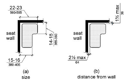
610.3.2 L-Shaped Seats. The rear edge of an L-shaped seat shall be 2 1/2 inches (64 mm) maximum and the front edge 15 inches (380 mm) minimum and 16 inches (405 mm) maximum from the seat wall. The rear edge of the "L" portion of the seat shall be 1 1/2 inches (38 mm) maximum from the wall and the front edge shall be 14 inches (355 mm) minimum and 15 inches (380 mm) maximum from the wall. The end of the "L" shall be 22 inches (560 mm) minimum and 23 inches maximum (585 mm) from the main seat wall.
610.4 Structural Strength. Allowable stresses shall not be exceeded for materials used when a vertical or horizontal force of 250 pounds (1112 N) is applied at any point on the seat, fastener, mounting device, or supporting structure.
611 Washing Machines and Clothes Dryers
611.1 General. Washing machines and clothes dryers shall comply with 611.
611.2 Clear Floor Space. A clear floor or ground space complying with 305 positioned for parallel approach shall be provided. The clear floor or ground space shall be centered on the appliance.
611.3 Operable Parts. Operable parts, including doors, lint screens, and detergent and bleach compartments shall comply with 309.
611.4 Height. Top loading machines shall have the door to the laundry compartment located 36 inches (915 mm) maximum above the finish floor. Front loading machines shall have the bottom of the opening to the laundry compartment located 15 inches (380 mm) minimum and 36 inches (915 mm) maximum above the finish floor.
612 Saunas and Steam Rooms
612.1 General. Saunas and steam rooms shall comply with 612.
612.2 Bench. Where seating is provided in saunas and steam rooms, at least one bench shall comply with 903. Doors shall not swing into the clear floor space required by 903.2.
EXCEPTION: A readily removable bench shall be permitted to obstruct the turning space required by 612.3 and the clear floor or ground space required by 903.2.
612.3 Turning Space. A turning space complying with 304 shall be provided within saunas and steam rooms.

