
Public Rights-of-Way Access Advisory Committee Final Report
Building a True Community
January 2001
Draft prepared by the Committee’s Editorial Subcommittee:
Janet Barlow, Pat Cannon (Board member), Dan Dawson, HolLynn D’Lil, Laurie Kozisek, Gina Hilberry (Illustrations Manager), Elizabeth Hilton, Jerry Markesino (Committee Chair), Charlie Nagel, Mary O’Connor, Debbie Ryan, Ellen Vanderslice, (Editorial Subcommittee Chair), Francine Wai, and Mark WalesAssistance provided by Access Board staff members:
Dennis Cannon, Beth Stewart, Lois Thibault, and Scott Windley
Part I: Introduction
THE PUBLIC RIGHT-OF-WAY
The public right-of-way is an ancient concept, as old as the notion of owning land. The commerce of humankind requires circulation, and since the days of the earliest cities, the public street has served as the venue and vessel for the exchange of ideas, opinions, services and goods. For centuries, public rights-of-way ensured the right to passage of all users, humble or grand, on foot or by any other mode.
However, only within the latter half of the last century has serious thought been given to the right to access for those who, historically, had never been considered at all in the built environment. Within the public right-of-way, efforts to accommodate people with disabilities have been accomplished on a state-by-state basis with guidance from various code-writing organizations, but there has been no single national set of guidelines for accommodating people with disabilities in the public right-of-way.
Public rights-of-way harbor many transportation activities, including walking and rolling, bicycling, transit, freight movement, and automobile travel. They house the hardware, such as traffic signals and street lights, that supports those activities. In many cases they contain public and private utilities. With so many diverse functions to be supported, the streetscape within the public right-of-way is often created over a period of time by a variety of minds and hands.
For the individual user the streetscape must work at an intimate level. Details at the individual scale can appear seamless and coherent if they are done right. As David Sucher notes in his book, City Comforts, “An ordinary, even banal structure, can and will be transformed into a marvel if the designer and builder have thought through the users’ needs and reflect those needs in the details.”
The following report is a recommendation for a new national set of guidelines that define the details necessary to make the streetscapes in public rights-of-way accessible to all users. This report has been prepared by the Public Rights-of-Way Access Advisory Committee (PROWAAC), convened by the U.S. Architectural and Transportation Barriers Compliance Board (the Access Board) to address access to public rights-of-way for people with disabilities.
The members of the PROWAAC represent a broad cross-section of design professionals, transportation industry professionals, implementing agencies, and a diverse range of advocates and users groups. This knowledgeable and representative advisory committee shared a commitment to this fundamental principle: that all users of all abilities have the right to equal access to public rights-of-way.
To that end, the PROWAAC developed a toolbox approach to defining standards which will provide that equal access to public rights-of-way. The goal of the toolbox approach is to aid implementing agencies and the designers who work in the public right-of-way to understand the needs of all users and design accordingly. Accessibility is not an afterthought. The design of a coherent corridor of accessible travel should be the starting point for every project in the public right-of-way. If these recommended standards are implemented, then over time public rights-of-way will achieve consistency and equal access for all users.
The guidelines proposed in this report do not call for a minor adjustment here and there, they ask for a dramatic change from the way public rights-of-way have been designed in the past. However, they do not require dramatic changes to streets that were built in the past. It is important to understand that the recommended standards, if adopted, will apply whenever new streets are created and whenever existing streets are reconstructed or otherwise altered in ways that affect their usability by pedestrians. Implementation of these recommendations will not require jurisdictions to rebuild existing streets solely to meet these standards.
BACKGROUND
The Americans with Disabilities Act (ADA) of 1990 is a civil rights statute that prohibits discrimination against people who have disabilities. Under the ADA, designing and constructing facilities for public use that are not usable by people who have disabilities constitutes discrimination.
The ADA covers a wide range of disability, from physical conditions affecting mobility, stamina, sight, hearing, and speech to conditions such as emotional illness and learning disorders. Such disabilities may or may not be evident to others. The percentage of the US population affected by a condition that constitutes a disability under the ADA is expected to increase over the coming decades, in part due to the growing numbers of the elderly.
The ADA addresses access to the workplace (title I), state and local government services (title II), and places of public accommodation and commercial facilities (title III). It also requires telephone companies to provide telecommunications relay services for people who have hearing or speech impairments (title IV) and miscellaneous instructions to Federal agencies that enforce the law (title V).
Public rights-of-way are covered by the ADA under title II, subpart A. The Department of Justice (DOJ) has rulemaking authority and enforcement responsibility for title II, while the Department of Transportation (DOT) has been designated to implement compliance procedures relating to transportation, including those for highways, streets and traffic management. The Federal Highway Administration (FHWA) Office of Civil Rights oversees the DOT mandate in these areas.
The Access Board is an independent Federal agency responsible for developing accessibility guidelines under the ADA to ensure that new construction and alterations covered by titles II and III of the ADA are readily accessible to and usable by individuals with disabilities. The Access Board initially issued the Americans with Disabilities Act Accessibility Guidelines (ADAAG) in 1991 (36 CFR 1191, Appendix A). ADAAG consists of general sections (ADAAG 1 to 4) that apply to all types of buildings and facilities, and special sections (ADAAG 5 to 12, and 15) that contain additional requirements for certain types of buildings and facilities.
The regulations issued by DOJ and DOT must include accessibility standards for newly constructed and altered facilities covered by title II. The standards must be consistent with the guidelines issued by the Access Board.
Rulemaking History
The Access Board published a Notice of Proposed Rulemaking (NPRM) in December 1992, proposing to add four special application sections to ADAAG applicable to certain types of state and local government buildings and facilities covered by title II of the ADA. One of the proposed sections was 14, Public Rights-of Way. The NPRM also proposed requirements and asked questions regarding the addition of miscellaneous provisions specifically applicable to state and local government facilities.
In June 1994, the Access Board published an interim final rule in the Federal Register that added several sections, including section 14, to ADAAG, along with miscellaneous other provisions. The interim final rule sought comment on the added sections and the miscellaneous provisions.
Many commenters, including public works agencies, transportation departments and traffic consultants, expressed concern that section 14 provisions would require wholesale rebuilding of existing developed rights-of-way. Others were concerned that the section 14 provisions were not reasonable because they did not adequately take into account the way jurisdictions construct and manage facilities in the public right-of-way. In January 1998, the Board published final rules for state and local governments, but decided to reserve section 14, due in large measure to concerns of the transportation community expressed in comments to the Board on the proposed and interim final rules.
The response to both the NPRM and the interim final rule clearly indicated the need for substantial education and outreach regarding the application of guidelines in this area. Rather than finalizing the guidelines for public rights-of-way, the Board embarked upon an ambitious outreach plan to the transportation industry. This outreach included producing a series of videotapes, an accessibility checklist, a synthesis syntheses on accessible pedestrian signals and on detectable warnings installations in the U.S. and abroad, and a design guide on accessible public rights-of-way. In addition, the Board has been actively involved with transportation industry organizations and has closely worked with the Federal Highway Administration on these issues.
In early 1999, the Access Board reviewed its education and outreach program and the impact on state and local government regulatory efforts in this area, and concluded that the development of final requirements for accessibility in the public right-of-way was appropriate. At its May 1999 meeting, the Access Board voted to reinitiate rulemaking on accessible pedestrian facilities in public rights-of-way by convening a Federal advisory committee to develop recommendations for guidelines for public rights-of-way covered by the ADA and the Architectural Barriers Act of 1968.
Establishing an Advisory Committee
The Public Rights-of-Way Access Advisory Committee (PROWAAC) was established in October 1999 as the first step in developing additional ADAAG provisions and special application sections. A notice of intent to form an advisory committee was published in the Federal Register on August 12, 1999. The notice proposed a committee membership and requested applications. Committee members represented the diverse interests of those affected by this rulemaking including persons with disabilities, federal, state, and local public works and transportation agencies, organizations representing design professionals, pedestrian and bicycle organizations, standard-setting organizations, and organizations representing the access needs of individuals with disabilities. The committee worked in a professional and collegial manner to establish this recommendation in a short period of time. The final membership of the committee is listed in Appendix A.
The committee met six times between December 1999 and December 2000 as a full committee. In addition, several subcommittees met physically, by telephone, and by e-mail to gather information or develop recommendations for the full committee. The committee participated in tours and informational presentations as part of their meetings. Committee members sought input from the public on issues related to accessibility of public rights-of-way. The meetings were held in different locations across the country and were attended by more than 100 members of the public. A formal public comment period was held at the end of each day of the full committee meetings. Among the issues that were brought to the attention of the committee were the effects of traffic calming devices, particularly vertical deflection devices such as speed humps, on people who suffer pain; the effects of weed control strategies on people with multiple chemical sensitivities; the need of people with hearing disabilities for accessible communication in the public right-of-way; the need of some blind people for unambiguous information presented in an audible and/or tactile format; and the ability of some blind people to use existing cues to travel independently, without the need for additional information.
The committee began its work by reviewing available information related to providing access for persons with disabilities in public rights-of-way. The committee reviewed the section 14 document included in ADAAG under the Access Board’s interim final rule issued in June 1994, the Board’s Accessible Rights-of-Way Design Guide, the Federal Highway Administration’s Designing Sidewalks and Trails for Access, and other similar information. They also examined and discussed approaches used by states and local governments to meet access responsibilities in the absence of specific ADAAG guidance, and discussed pending design documents such as the American Association of State Highway and Transportation Officials’ (AASHTO) Pedestrian Design Guide.
Basic Principles
The committee’s discussions were guided by basic principles. PROWAAC members believed that accessibility standards for pedestrian facilities in public rights-of-way should:
- Provide for equal opportunity
- Maximize accessibility for all users
- Be reasonable
- Be clear, simple and understandable
- Be enforceable and measurable
- Be constructible and maintainable within today’s technological capabilities
- Address safety for both pedestrians and motor vehicle operators
- Provide guidance for implementing agencies and the public
- Be flexible enough to include future technologies
- Be consistent with ADAAG
- Support independent use by persons with disabilities
The advisory committee explored many approaches and compromised in many areas to reach agreement on recommended accessibility standards for new and altered public rights-of-way covered by the ADA. The standards proposed by the committee and presented in this report include consideration of the latest available information and design and construction practices.
The PROWAAC presents this report to the Access Board at the Transportation Research Board’s (TRB) annual meeting in January, 2001. The report addresses the variety of facilities in the public right-of-way and identifies the features of each facility not adequately addressed by ADAAG. This report presents the recommendations of the PROWAAC for accessibility standards for those features.
What’s next?
The Access Board will consider these recommendations and write a proposed rule, which will be published in a Notice of Proposed Rulemaking (NPRM). Interested parties will then have a chance to comment on the NPRM before the Department of Justice and/or the Department of Transportation considers whether to issue a final rule.
Some agencies may begin to use the recommendations in this report as guidance even before a final rule is adopted. These recommendations represent the best judgment of the committee on a very large number of issues as developed in a relatively short period of time. However, it should be noted that, inevitably, there are some recommendations in this report, as well as some issues for which recommendations were reserved, where the outcome might have been different had there been more time for the committee to discuss and test what is proposed. The period for public comment will allow these recommended standards to be further refined into a final rule that truly embodies the basic principles that guided the committee.
SOME ISSUES CONSIDERED BY THE COMMITTEE
- The need for larger dimensions in the public right-of-way
- What to call the “corridor of accessible travel” in the public right-of-way
- Wayfinding in public rights-of-way for blind persons or those with low vision
- Flexibility of the standards with respect to emerging technologies
- The variety of needs, sometimes competing, of users with diverse disabilities
- Extension of the pedestrian access route into the roadway at crosswalks
- The need for pedestrian access on all urban roadways
- Maintenance of pedestrian access routes and accessible features
- Consistency with other reports
The need for larger dimensions in the public right-of-way
While fully understanding that the standards must require the minimum dimensions necessary for access, rather than setting desirable or preferred dimensions, PROWAAC members considered the possibility that larger dimensions were necessary in public rights-of-way to provide adequate accessibility.
The committee recognized that maneuvering clearances needed in the public right-of-way may be greater than the clearances needed in a building or facility. Travel in the public right-of-way is generally faster and often may take place under circumstances requiring larger mobility aids. Pedestrians, including persons with disabilities, are much more likely to travel side-by-side or in groups in the public right-of-way. The committee recognized that some people who use crutches require as much as 42 inches (1065mm) of usable width to support travel, and people with service animals or sighted guides will use a minimum of 48 inches (1220mm). The committee also considered that at least 60 inches (1525mm) of width are required for a variety of wheelchairs currently in use to turn or pass; and that 72 inches (1830mm) are required for two wheelchair users to travel side-by-side.
What to call the “corridor of accessible travel” in the public right-of-way
PROWAAC members spent considerable time working to identify a term that would represent an analog in the public right-of-way to the term “accessible route,” the basic unit of accessibility for title III entities under ADAAG. This concept was called “continuous passage” in proposed section 14.
The committee discussed the notion of a three-dimensional corridor through which sidewalk travelers could easily move. Designers should understand this as a spatial concept, not just a given expanse of concrete or asphalt. This continuous corridor of accessible travel, threading its way along sidewalks and across driveways and roadways, free of abrupt changes in level, with a clear width of at least sixty inches and a clear height of at least eighty inches, assures access for all sidewalk travelers, from those who use wheelchairs to those who push strollers to those who find their way with a cane.
In searching for the right name for this corridor, the committee took into account the concern that any term very similar to “accessible route,” or incorporating the phrase, might lead to confusion. The committee recognized that a corridor in the public right-of-way will have different requirements than the “accessible route” on a site. Creating a distinct name helps avoid any confusion between the requirements proposed for the public right-of-way and those requirements already in existence that apply to a site.
A further concern was to avoid disrespect to any sidewalk travelers. After much debate, the majority of the committee supported the term pedestrian access route, and that term is used throughout this report. However, some members felt strongly that the word pedestrian, although defined in this report and commonly used among designers to denote all sidewalk travelers, has its roots in the Latin word for feet, and thus is not the best choice to describe those who use wheelchairs for mobility.
Wayfinding in public rights-of-way for blind persons or those with low vision
PROWAAC members recognized there is a significant need for wayfinding for pedestrians who are blind or have low vision. The committee’s recommendations to the Access Board include a number of proposed standards that will, if adopted, provide additional guidance about signs, street crossing controls, pedestrian signals, crossing times and other items. The committee also recognizes that technological changes are occurring rapidly, with the potential to greatly improve access for persons with visual impairments over time. The committee recommends continual review of technology in this area to provide advisory guidance to communities in establishing wayfinding systems.
Flexibility of the standards with respect to emerging technologies
PROWAAC members understood that new technologies are constantly emerging. These recommended standards are intended to be flexible enough to accommodate new technologies, particularly wayfinding technologies, but also new mobility devices, new signal technologies and other technologies that may emerge to increase access and mobility for pedestrians who have disabilities.
The variety of needs, sometimes competing, of users with diverse disabilities
PROWAAC members gave great attention to the needs of all users of public rights-of-way who have disabilities. The committee recognized that efforts to increase access and usability for some pedestrians have caused, or may cause, problems for others with different disabilities. For example, the proliferation of curb ramps in the public rights-of-way has greatly increased access for pedestrians using wheelchairs, scooters and other wheeled mobility aids. However, the curb formerly provided an important cue to blind pedestrians, and where curb ramps are installed that cue has now been lost or diminished. The recommendations for detectable warnings at curb ramps and flush landings are an example of the committee’s desire to address these issues.
Extension of the pedestrian access route into the roadway at crosswalks
PROWAAC members recognized that travel by pedestrians with disabilities in public rights-of-way is not limited to sidewalks, and that crosswalks in the roadway are an integral part of the pedestrian access route. The committee worked to develop reasonable standards for crosswalks in new roadways that will foster access for all users.
The need for pedestrian access on all urban roadways
PROWAAC members conceded that the ADA does not require the construction of sidewalks in public rights-of-way, but only requires that, where provided, such facilities meet the standards for accessibility, and that it is not within the purview of this committee to alter the scope of the law. However, in support of the rights of all users, including those who do not use motor vehicles, to access destinations via public rights-of-way, the committee adopted a resolution to express their support for identifying a mechanism to require that sidewalks be included whenever a road is constructed or reconstructed in a public right-of-way in an urban area. (See Appendix C)
Maintenance of pedestrian access routes and accessible features
PROWAAC members recognized the importance of maintaining pedestrian access routes and features such as crosswalk locators and signals, railings, pavement markings and surfaces intended for use by people with disabilities. The committee also recognizes that state and local governments have a maintenance responsibility under the Department of Justice’s rules barring discrimination on the basis of disability in state and local government services. However, the committee also recognizes that municipalities differ in how things are accomplished. For example, in some communities, adjacent property owners are required to construct sidewalks, to repair and maintain them, and to clear snow or other hazards from sidewalks. Some communities have the ability to establish proactive programs that look for problems and fix them, while others may only respond to citizen complaints.
Attempting to codify how and when state and local governments must identify problems and resolve them is beyond the scope of the committee. Public entities are encouraged to establish procedures that will assure that maintenance activities are undertaken by the responsible individuals and entities in ways that minimize inconveniences to individuals with disabilities, consistent with Department of Justice regulations.
The committee also attempted to provide information for temporary facilities and construction in the pedestrian access route, including options for warnings, signage and barricades, and alternate circulation paths. Examples of construction barricading standards which maintain pedestrian access routes during construction are available from communities such as San Francisco, California.
Consistency with other reports
PROWAAC members attempted to be consistent with the recent recommendations of other Access Board subcommittees, such as the Recreation Access Advisory Committee and the Regulatory Negotiating Committee for Outdoor Developed Areas, regarding elements that are commonly found in parks, recreation areas, and related public rights-of-way. Some examples include benches, tables, trash receptacles, and artwork. The committee also attempted to be consistent with proposed ADAAG and used it as the reference standard to the extent practicable.
The committee identified some potential gray areas, such as whether the guidelines for the public rights-of-way or guidelines for recreation access should be applied in cases of shared use paths or trails within public rights-of-way. The Access Board will need to decide where each set of guidelines applies.
The committee coordinated their efforts with those of national transportation standard-setting organizations like the American Association of State Highway and Transportation Officials (AASHTO) and federal agencies such as the United States Department of Transportation to assure that recommendations are consistent with generally accepted practice among design professionals.
THE STRUCTURE AND FORMAT OF THIS REPORT
The recommendations of the PROWAAC for standards for construction in the public right-of-way are found in Part III of this report. These recommendations are briefly summarized in Part II, Executive Summary of Recommended Standards. Within the recommendations, information is provided in the form of recommended standards followed by a discussion section, as described below. Numbering has been done using a generic “X” to represent the number of the chapters that will eventually be assigned to the public rights-of-way accessibility guidelines. Where cross references to material in these recommendations or in proposed ADAAG are given, the sections are referenced. Terms that are defined in X01.2 are generally italicized the first time they appear in a numbered provision.
Executive Summary
An executive summary is provided that highlights the recommended standards in this report and the list of recommended research. Each summary is a short list of the basic technical provisions of the associated standard. The summaries are provided for convenience; however, readers are strongly advised to consult the complete text of the standard language and its associated discussion section for a full understanding of the recommended requirements.
Recommended Standards
These are recommendations from the PROWAAC to the Access Board on requirements to achieve accessibility in the public right-of-way. Standards are numbered and arranged according to a hierarchy: some standards have many sub-elements; others do not. Each standard or sub-element of a standard includes the following parts:
Scoping Provisions This part describes where the standard applies and which elements must meet the technical provisions.
Technical Provisions
This part describes the specifications to meet the standard. Measurements in the technical provisions are provided in both English and metric units.
A standard or sub-element of a standard may also include the following elements:
Figure(s)
Figures are provided as an aid to understanding the technical provisions. No technical provisions are specified in the figures that are not also specified in the text of the technical provisions.
Advisory Notes
Advisories provide clarification and intent concerning the standards. In some cases, non-mandatory recommendations are included as guidance. With further research or discussion, these recommendations could be forwarded to the proposed rulemaking process.
Discussion
The discussion for each standard offers insight for those who may draft proposed rules, as well as designers and end users, regarding issues that the committee considered and the rationale for their decision whether or not to include a recommended standard. This may be of interest particularly for those standards where full agreement among the committee was not achieved.
The discussion also includes issues that were considered to be “frontier issues,” or issues requiring resolution, along with recommendations for additional action, in the form of further research or in the form of questions for the Access Board to ask in rulemaking.
Frontier issues are defined as those issues identified by PROWAAC members for future study and rulemaking by the Access Board, which could not be addressed due to committee time constraints or need for additional research. Examples of these frontier issues include: final recommendations for applicability of new construction standards to alterations, and detailed definition of alterations; and acceptable surface treatments within and outside the pedestrian access route.
Appendices
Eleven appendices to this report are provided. The first two appendices include information regarding the structure and function of the PROWAAC. The rest of the appendices provide clarification, or voice specific concerns which either reflect the consensus of the committee or minority opinions. Appendix C is a resolution urging those with the power to do so to mandate construction of sidewalks. Appendix D identifies preliminary concepts for applying the new construction standards in this report to alterations of existing work. Appendix E consolidates references within the body of the report regarding research needs, recommended questions, and frontier issues. Appendix F is a list of the acronyms and abbreviations used in this report. Subsequent appendices represent minority reports from individuals or groups represented on the committee who wished to highlight their concerns about specific issues.
Part II: Executive Summary of Recommended Standards
The following is a summary of the recommended standards, scoping, and technical provisions, provided as an easy reference. Readers are strongly advised to consult the complete text of the standard language and its associated discussion section for a full understanding of the recommended requirements.
GENERAL (X01)
- Requirements are applicable to new construction and alterations, as provided for in some provisions.
- Requirements for additions and alterations are consistent with proposed ADAAG Section 202. Concepts of technical “infeasibility”, “compliance to the maximum extent feasible”, “equivalent facilitation”, and “historic preservation” are maintained from current and proposed ADAAG.
NEW CONSTRUCTION: MINIMUM REQUIREMENTS (X02)
Public Sidewalks (X02.1)
Pedestrian access route (X02.1.2)
- Sidewalks shall contain a pedestrian access route and a reduced vibration zone.
Clear Width (X02.1.3)
- The minimum clear width of the pedestrian access route shall be 60 inches (1525mm).
- The clear width of the pedestrian access route may be reduced to 48 inches (1220mm) at driveways and alley crossings, accessible parallel parking locations with constraints, where necessary to make building entrances accessible, and at street fixtures.
- The minimum clear width for the reduced vibration zone shall be 48 inches (1220mm).
Cross Slope (X02.1.4)
- The maximum cross slope on the pedestrian access route shall be 1:48.
Grade (X02.1.5)
- Grades consistent with the adjacent roadway are permitted on pedestrian access routes.
- Grades steeper than the adjacent roadway are only permitted if they are: 1) less than 5 percent; 2) in compliance with proposed ADAAG Section X02.4; or 3) in compliance with proposed ADAAG Section 405.
Surfaces (X02.1.6)
- Surfaces on pedestrian access routes shall comply with proposed ADAAG Section 302 and be as free of joints and as visually uniform as possible.
- Utility covers and grates are not allowed within the 48-inch reduced vibration zone.
- At rail crossings, allow a 2-1/2-inch maximum gap with an exception for a 3-inch gap for freight lines. This allowance expires 4 years after adoption of the final rule.
- Detectable warnings are required where rail lines cross non-vehicular pedestrian facilities.
Changes in Level (X02.1.7)
- Changes in level on pedestrian access routes shall comply with proposed ADAAG Section 303.
Stairs (X02.1.8)
- Stairs within the public right-of-way shall comply with proposed ADAAG Section 504.
- Stairs shall not be a part of the pedestrian access route.
- Visual contrast is required at leading edges.
Elevators and Lifts (X02.1.9)
- Elevators and lifts within the public right-of-way shall comply with proposed ADAAG Section 407 and Section 408 and remain unlocked during operating hours of the facility being served.
Separation (X02.1.10)
- Reserved; vertical and horizontal separation of the sidewalk from the street is encouraged.
Edge Conditions (X02.1.11)
- Reserved; tactile cues and edge protection are encouraged in some circumstances.
Handrails (X02.1.12)
- Handrails provided in the public right-of-way shall comply with proposed ADAAG Section 505.
Parking structure exit warnings (X02.1.13)
- Reserved; provision of driver alerts at exits to parking structures is encouraged and research is recommended.
Protruding Objects (X02.2)
Wall-mounted objects (X02.2.2)
- Wall-mounted objects with a leading edge between 27 inches and 80 inches above ground shall protrude no more than 4 inches, with an exception for handrails.
Post-mounted objects (X02.2.3)
- Post-mounted objects with a leading edge between 27 inches and 80 inches above ground shall protrude no more than 4 inches.
- Where objects or signs are mounted between two posts spaced more than 12 inches apart, a cross bar 15 inches above the ground connecting the two posts is required.
Reduced vertical clearance (X02.2.4)
- Railings or other barriers with a leading edge no more than 27 inches high are required if the vertical clearance is less than 80 inches.
Street Fixtures and Furniture (X02.3)
Requirement for accessible street furniture (X02.3.1)
- Street furniture shall be connected to the pedestrian access route.
- Street furniture intended for use by pedestrians shall comply with proposed ADAAG Section 305, Section 306, Section 308, Section 309, and other applicable sections.
- Clear floor or ground space for street furniture shall not encroach into the pedestrian access route by more than 24 inches.
Drinking fountains and water coolers (X02.3.2)
- A minimum of 2 drinking fountains is required unless the single fountain is a hi-lo type combination.
- Single hi-lo type drinking fountains shall comply with proposed ADAAG Section 602.
- Fifty percent of all drinking fountains in a cluster shall comply with proposed ADAAG Section 602.1 through Section 602.6.
Public telephones (X02.3.3)
- Single installations of public telephones shall comply with proposed ADAAG Section 704.2, Section 704.4 and Section 704.5.
- Where two or more public telephones are clustered together, at least one shall comply.
- All telephones shall provide volume controls in compliance with proposed ADAAG Section 704.3.
Public toilet facilities (X02.3.4)
- Permanent public toilet facilities in the public right-of-way shall comply with proposed ADAAG Section 603 and shall provide 48 inches minimum clearance in front of the water closet.
- Where provided, at least one toilet compartment shall comply with proposed ADAAG Section 604; if six or more compartments, an ambulatory accessible compartment shall also be provided.
- At least one of each of the following shall comply with the following sections: water closets with proposed ADAAG Section 604, urinals with proposed ADAAG Section 605, lavatories with proposed ADAAG Section 606, mirrors with proposed ADAAG Section 603.3, operable parts and dispensers with proposed ADAAG Section 309.
Fixed tables, counters and benches (X02.3.5)
- When fixed tables or counters are provided, not less than one shall comply with Section X02.3.5.3 for clear ground space and Section X02.3.5.4 for height; a clear ground space providing for a forward approach with knee and toe clearance shall be provided.
- At benches without tables, at least 50% of benches at a single location shall have a back and armrests and the clear ground space shall be positioned to allow wheelchair users to be seated shoulder-to-shoulder with an individual seated on the bench.
- Exceptions are made when tables are provided for children’s use.
Bus stop pads and shelters (X02.3.6)
- Bus stop pads and shelters are covered in separate accessibility guidelines adopted by the U.S. Department of Transportation.
- A route to and into a shelter and the size of a bus stop pad for the deployment of onboard lifts and ramps are regulated.
Depositories, vending machines, change machines and trash receptacles (X02.3.7)
- Where provided at a single location, at least one of every type of these facilities shall comply with proposed ADAAG Section 305, Section 308, and Section 309; exceptions are drive-up only depositories.
Street identification and other pedestrian signage (X02.3.8.1 - X02.3.8.6)
- Street identification signs, including bus stop signs, shall meet readability criteria.
- Readability criteria include: eggshell finish; minimum 70 percent visual contrast; character size based upon intended viewing distance; character width 60 percent to 100 percent the height of the character; tactile characters with rounded or trapezoidal cross section; minimum stroke thickness of 1/32 of an inch; mounting height 60 inches above adjacent clear landing space, excepting bus stops and shelters.
Changeable or variable message signs (X02.3.8.7)
- Changeable or variable message signs shall be legible from the same distance as conventional print; short messages shall be static, with no paging messages permitted.
Audible signs (X02.3.8.8)
- Where there are audible signs, a visual equivalent shall be provided.
- Remote Infrared Audible Sign (RIAS) receivers shall follow a consistent protocol so that one receiver may be used to acquire basic wayfinding information.
Sidewalk/Street Transitions (X02.4)
General (X02.4.1)
- A curb ramp or flush landing is required wherever the pedestrian access route crosses a sidewalk/street transition.
- If at least one corner of an intersection has a public sidewalk, then all corners require curb ramps or flush landings.
- A separate curb ramp or flush landing is required for each direction of travel.
- A landing is required at the top of each curb ramp, except at unsignalized driveways.
- A landing is required at the top and bottom of each transition ramp, except at unsignalized driveways.
Placement (X02.4.2)
- The sidewalk/street transition shall be aligned within a legal crosswalk or parking access aisle.
- There shall be room for a 48-inch by 48-inch maneuvering area in the crosswalk, adjacent to the sidewalk/street transition.
- Curb ramps and flush landings shall be wholly contained within the public sidewalk and shall not protrude into the vehicular way.
- Curb ramps are permitted to protrude into accessible parking aisles if they do not intrude into the maneuvering and unloading areas.
Directionality (X02.4.3)
- Reserved; with advisory language to encourage directionality provided that the cross slope of the ramp does not exceed 1:48.
Width (X02.4.4)
- The minimum clear width of a curb ramp shall be 48 inches.
- The minimum clear width of a transition ramp shall be the width of the pedestrian access route.
Landing size (X02.4.5)
- Landings must contain a 60-inch square or 60-inch circle.
- Landings may serve multiple ramps or overlap with other landings.
Running grade (X02.4.6)
- The maximum running grade of any portion of any curb ramp or transition ramp shall be 1:12.
- Curb ramps and transition ramps are not required to exceed 15 feet.
Cross slope and warp (X02.4.7)
- The maximum curb ramp and transition ramp cross slope shall be 1:48.
- The maximum cross slope for landings shall be 1:48 in any direction.
- Warping is to be minimized.
Counter slope (X02.4.8)
- The algebraic difference in grade at the ramp/street interface shall not exceed 11 percent.
- Multiple grade breaks shall be separated by at least 24 inches.
Edge conditions (X02.4.9)
- Curb ramps shall have flares if pedestrians might walk across them.
- Flare length along the curb line shall be at least ten times as long as the adjacent curb height.
- Where transition ramps that are not full sidewalk width are installed, pedestrians shall be protected from walking across the diverging grade in the public sidewalk.
Surfaces (X02.4.10)
- The surface of curb ramps and landings shall be stable, smooth and slip resistant.
- Gratings, access covers and similar surfaces shall not be located on curb ramps, transition ramps, landings, or adjacent gutter pans at sidewalk/street transitions.
Vertical grade breaks and lips (X02.4.11)
- No vertical changes in level or lips are allowed on or between components of curb ramps, landings, the street, and the gutter.
Detectable warnings (X02.4.12)
- Sidewalk/street transitions shall have detectable warnings complying with Section X02.5.7.
Vehicular obstructions (X02.4.13)
- Sidewalk/street transitions shall not be blocked by legally parked cars.
Curb type (X02.4.14)
- Reserved; identifies “frontier issue” regarding appropriate use of rolled curb.
Pedestrian Street Crossings (X02.5)
Pedestrian signal push buttons (X02.5.1)
- Push buttons shall be at least 2 inches across, have a locator tone, require activation force of no greater than 3.5 lbs., be operable with a closed fist, have visual contrast of at least 70 percent, and provide audible and visible indication that the button has been pressed.
- Push buttons shall be located adjacent to a clear level landing, adjacent to the landing of a curb ramp or transition ramp, with a maximum mounting height of 42 inches, parallel to the direction of the crosswalk, no further than 5 feet from the extension of the crosswalk lines and within 10 feet of the curb line.
- Multiple push buttons with an accessible pedestrian control on the same corner must be at least 10 feet apart, with exceptions.
- Tactile arrows on controls shall indicate directionality.
- When a map of a crosswalk is provided with a push button, it shall be visual and tactile.
- Locator tones, where required, shall be 2dB - 5dB greater than ambient noise, be 0.15 seconds in duration, have one second repetition intervals, and deactivate during flashing intervals.
Accessible pedestrian signals (X02.5.2)
Accessible pedestrian signals are required in certain situations:
1) where pedestrian phase timing is pedestrian actuated;
2) where there is a leading pedestrian interval (LPI);
3) where there is a pretimed signal with pedestrian signal information.
- Accessible pedestrian signals must indicate unambiguous directionality in audible and vibrotactile format, must have a locator tone if pedestrian activated, be audible from the beginning of the walk interval, must differentiate between walk interval and locator tones, shall be 2dB - 5dB greater than ambient noise, and not be limited in operational hours.
- Audible beaconing, if provided, shall be during walk intervals only.
Other pedestrian signals and timing controls (X02.5.3)
- Requirements at mid-block crosswalks are reserved.
- Requirements for near side pedestrian signals are reserved.
Crosswalks (X02.5.4)
- The crosswalk cross slope (road grade) shall be a maximum of 1:48.
- The crosswalk running grade (road crown or superelevation) shall be a maximum of 5 percent.
- Crosswalk markings are required at signalized intersections.
- The minimum crosswalk width is 8 feet.
Crossing times (X02.5.5)
- Pedestrian signal phase timing shall be calculated with a 3.5 feet per second pedestrian walk speed.
- Crossing distances, when calculating timing, shall include the length of the crosswalk and one curb ramp.
Medians and pedestrian refuge islands (X02.5.6)
- Compliant cut-throughs or curb ramps are required.
- Detectable warnings are required.
Detectable warnings (X02.5.7)
- Detectable warnings shall be provided only:
1) where a pedestrian way crosses a vehicular way, but not at unsignalized driveways;
2) where a rail system crosses a pedestrian way;
3) at reflecting pools in the public right-of-way;
4) at cut through islands and medians; and
5) where required by proposed ADAAG Chapter 10. - Specifications are provided for size, location, dome spacing and size, alignment, and visual contrast.
Pedestrian overpasses and underpasses (X02.5.8)
- Overpasses and underpasses must connect to a pedestrian access route.
- An elevator is required if more than 5 percent grade is required for greater than a 5-foot vertical rise.
- Signs must be tactile and visual and comply with proposed ADAAG Section 504.
Roundabouts (X02.5.9)
- Barriers must be provided where pedestrian crossings are prohibited.
- A cue must be provided to locate the pedestrian crossing.
- A pedestrian activated traffic signal must be provided at pedestrian crossings.
Turn lanes at intersections (X02.5.10)
- A cue must be provided to locate the pedestrian crossing.
- A pedestrian activated traffic signal must be provided at pedestrian crossings.
Vehicular Ways and Facilities (X02.6)
On-street parking (X02.6.1)
- The number of accessible spaces shall comply with proposed ADAAG Section F208.2.
- One in eight, but at least one, accessible space must be van accessible.
- Accessible stalls shall be dispersed within a project area; clustering is allowed if it provides equivalent or greater access.
- Spaces shall be a minimum of 8 feet by 18 feet.
- Access aisles are required: 8 feet for van accessible spaces, 5 feet for others
- Maximum slope in accessible space is 1:48 in any direction.
- Signage is required.
- Adjacent areas must be free of obstructions.
Parking meters (X02.6.2)
- Controls shall be mounted no higher than 42 inches above the sidewalk.
- Controls shall have an operating force of less than 5 lbs.
- A clear space of 30 inches by 48 inches in front of the controls is required.
- Accessible meters shall be placed within 3 feet of the head or foot of the accessible stall, with an exception for centralized collection.
- Instructions may not be displayed solely on the horizontal surface of meter.
Passenger loading zones (X02.6.3)
- Curb ramps are required at least every 100 feet.
- The minimum dimension of a passenger loading zone shall be 8 feet by 20 feet.
- A 5 foot access aisle is required.
- Any signage provided shall comply with X02.3.7(A).
Motorist aid communication systems (X02.6.4)
- Controls shall have an operating force of less than 5 lbs., be located a maximum of 48 inches high, labeled in Braille and centered on clear ground space.
- A minimum of 72 inches by 72 inches clear ground space is required.
- A minimum of 16 feet by 23 feet level turnout connected to clear ground space is required.
- Any 2-way communication must provide TTY, VCO and HCO.
- Handsets, volume control and TTY specifications are included.
Overlooks (X02.6.5)
- Provisions comply with recommendations from the Regulatory Negotiation Committee for Outdoor Developed Areas.
Vertical and horizontal deflection measures (X02.6.6)
- A level clear width of 36 inches must be provided for passage if no pedestrian access route exists in the public right-of-way.
Motor vehicle turnouts (X02.6.7)
- Reserved; advisory for minimum paved area 16 feet by 23 feet, slope exceeding 1:48 in any direction, to allow turnout to be used by person with disability needing to service vehicle.
TEMPORARY FACILITIES AND CONSTRUCTION (X03)
Alternate Circulation Path (X03.1)
- An alternate route (alternate circulation path) shall be provided whenever the pedestrian access route is blocked.
Barricades (X03.2)
- Barricades shall be provided when construction occurs in the public right-of-way.
Warnings and Signage (X03.3)
- Warnings shall be provided when an alternate circulation path is provided or a barricade is constructed.
Temporary Facilities (X03.4)
- Temporary facilities in the public right-of-way must conform to the requirements for permanent facilities.
Part III: Recommended Standards, Scoping and Technical Provisions
X01 GENERAL
X01.1 Applicability of this Section
This report recommends scoping and technical requirements for accessibility within public rights-of-way by individuals with disabilities. These requirements are intended to be applied during the project development, design, construction and alteration of elements in the public right-of-way to the extent required by regulations issued by Federal agencies under the Americans with Disabilities Act of 1990.
Advisory: The recommended standards in this report reflect the hierarchical concept of a “path within a path.” Some provisions in these recommendations apply to the entire public sidewalk, while other provisions apply only to the pedestrian access route. Within the pedestrian access route is an “inviolate” reduced vibration zone. The scoping provisions for each standard lay out where it is to be applied.
X01.1.1 Equivalent Facilitation
Nothing in this report is intended to prevent the use of designs or technologies as alternatives to those prescribed in this report provided they result in substantially equivalent or greater accessibility and usability.
X01.2 Definitions
X01.2.1 General
The provisions of proposed ADAAG Section 106.1, Section 106.2, Section 106.3, Section 106.4 apply to this section.
X01.2.2 Defined terms
- Acceptance Angle
- the maximum range of transmission, measured with respect to 90 degrees in all directions, within which *remote infrared audible sign *systems remain operational, as measured at the transmitter.
- Accessible Pedestrian Signal (APS)
- a device that communicates information about pedestrian signal timing in non-visual format, through the use of audible tones (or verbal messages) and vibrating surfaces.
- Actuated Control
- operation of a traffic signal controller unit in which some or all signal phases are operated on the basis of actuation. Pedestrian actuation is typically by push button operation.
- Actuation
- initiation of a change in traffic signal phase through the operation of any type of detector.
- Alternate Circulation Path
- a detour or temporary route provided as a substitute for the pedestrian access route.
- Assistive Listening Device
- a device to help persons with hearing disabilities listen to audible information.
- Audible Beacon
- a permanently fixed source emitting sound for directional orientation.
- Barricade
- an obstruction to deter the passage of persons or vehicles.
- Central Island
- raised area around which traffic circulates at a roundabout.
- Changeable Message Sign or Variable Message Sign (CMS, VMS)
- an electronic sign with the flexibility to display various messages to provide information to pedestrians.
- Channelizing Island
- curbed or painted area outside the vehicular path provided to control and direct traffic movement into the proper lane for its direction. May also serve as a refuge island for pedestrians.
- Cluster
- two or more similar pedestrian-related elements located in close proximity in the public right-of-way.
- Contrast
- (See Visual Contrast.)
- Counter Slope
- any slope opposing the running grade of a portion of the pedestrian access route; in particular, the cross slope of the road or gutter pan at the base of a curb ramp *or flush landing*.
- Cross Slope
- the slope or grade of a surface perpendicular to the running grade.
- Crosswalk
- that part of a roadway where motorists are required to yield to pedestrians crossing, as defined by state and local regulations, whether marked or unmarked.
- Curb Line
- a line that represents the extension of the face of the curb and marks the transition between the public sidewalk and the gutter or roadway at a curb ramp or flush landing.
- Curb Ramp
- a short section of the pedestrian access route, with a running grade greater than 1:20, that joins the street elevation to the public sidewalk elevation, through a cut in the curb face. (Formerly called “perpendicular curb ramp,” related subject found at Transition Ramp.)
- Detectable Warning
- a standardized surface feature built in or applied to walking surfaces or other elements to warn people who are blind or visually impaired of specified hazards.
- Detector
- a device used for determining the presence or passage of vehicles or pedestrians. May be an active system that requires a pedestrian to push a button, or a passive system that automatically detects vehicles or pedestrians by such means as video, microwave, infrared, or embedded loops.
- Driveway
- a private vehicular way giving access from a public right-of-way to adjacent property.
- Eggshell Finish
- extent of gloss within a range of from 11 to 19 degree gloss on a 60 degree gloss meter. Eggshell is a function of reflectivity, not of color or contrast.
- Field of View
- the maximum angle of transmission, measured from 90 degrees in all directions, within which remote infrared audible sign systems remain operational, as measured at the receiver.
- Fixture
- a fixed element in the public right-of-way that is not intended for public use and does not require clear ground space for approach or use, such as a street light pole, fire hydrant or signal controller cabinet. (Related subject at Street Furniture.)
- Flare
- the sloping part of a public sidewalk adjacent to a curb ramp that provides a transition between the running grade of the curb ramp and the public sidewalk level.
- Flush
- when two portions of public sidewalk and/or roadway join, without vertical separation or lip.
- Flush Landing
- a landing on the public sidewalk side of a sidewalk/street transition, or where a median or island is cut through, that is flush with and at the same level as the roadway; often also the lower landing of a transition ramp.
- Grade
- the rate of ascent or descent of a surface with respect to a level plane, expressed as a percent; the change in elevation per unit of horizontal length.
- Grade Break
- an abrupt difference between the grade of two adjacent surfaces.
- Guardrail
- traffic barrier used to shield errant vehicles from potentially hazardous areas.
- Handrail
- a fixed continuous element at a specified height provided for pedestrian use where there is a change of elevation, such as ramps, stairs and landings
- Hearing Carry Over (HCO)
- a telecommunication relay service that enables a person with a speech disability to relay a typed telephone message through a text telephone (TTY), and to hear responses directly from the other party.
- Improved Surface
- an area that, by the addition of materials or its treatment, provides a firm, stable and immovable base for pedestrian movement. Examples of such materials include asphaltic concrete paving, portland cement concrete, stone, ceramics, wood, metal, fiberglass, or other generally firm, stable material. Surfaces that have only firmly packed earth, gravel base, gravel, vegetation, wood chips, shells, or other malleable material are not considered, for the purpose of this definition, to be improved surfaces.
- Island
- a defined area between traffic lanes for control of vehicular movements or for pedestrian refuge. Within an intersection area, a median is considered to be an island.
- Landing
- a level area with a cross slope of less than 1:48 in any direction in a public sidewalk, adjoining a transition ramp, curb ramp, ramp or sidewalk/street transition, used for maneuvering and waiting.
- Leading Pedestrian Interval (LPI)
- a pedestrian WALK phase that begins before the green interval serving parallel traffic, rather than at the same time.
- Lip
- a change of level occurring at the meeting point of two elements in the public right-of-way, such as at the boundary between a driveway apron and the roadway.
- Locator Tone
- a repeating sound that informs approaching pedestrians that they are required to push a button to actuate pedestrian timing and that enables pedestrians who are visually impaired to locate the push button.
- Maneuvering Space
- an area within the crosswalk at the foot of a curb ramp that is provided for users of mobility devices to align properly with the curb ramp.
- Median Refuge
- an area within an island or median that is intended for pedestrians to wait safely for an opportunity to continue crossing.
- Mid-block Crosswalk
- a crosswalk that is not at an intersection.
- Neighborhood Traffic Circle
- an intersection treatment in which a small, usually circular, raised island is placed in an intersection, about which traffic circulates. The intersection is typically controlled by a YIELD sign on all approaches. Typically the crosswalks at the intersection remain unchanged. Sometimes called an intersection island.
- Paging Message
- a message on a CMS that “pages up” from the bottom rather than moving from side to side.
- Passenger Loading Zone
- an area immediately adjacent to, but offset from the vehicular way, whether marked or unmarked, that is used for the unloading and loading of passengers from a vehicle.
- Pedestrian
- a person traveling the public right-of-way by means of a wheelchair, electric scooter, legs, crutches or other walking devices or mobility aids.
- Pedestrian Access Route (PAR)
- a corridor of accessible travel through the public right-of-way that has, among other properties, a specified minimum width and cross slope.
- Pedestrian Clearance Interval
- that phase of a traffic signal cycle in which pedestrians in the crosswalk may continue to cross but pedestrians on the curb should wait for the next cycle, typically indicated by a flashing illumination of a red hand symbol or the words DON’T WALK.
- Pedestrian Crossing Interval
- the combined phases of a traffic signal cycle provided for a pedestrian crossing in a crosswalk, after leaving the top of a curb ramp or flush landing, to travel to the far side of the vehicular way or to a median, usually consisting of the walk interval plus the pedestrian clearance interval.
- Pedestrian Overpass
- a grade-separated structure that carries pedestrian traffic over a road, railroad, waterway or other feature
- Pedestrian Signal Indication
- the illuminated WALK/DON’T WALK message (or walking person/hand symbols) that communicate the pedestrian phase of a traffic signal, and their audible equivalents.
- Pedestrian Underpass
- a grade-separated structure that carries pedestrian traffic under a road or railroad or other feature.
- Pretimed Control
- a condition at a traffic signal where the lengths of the red, yellow and green intervals are predetermined.
- Project Area
- the entire width of the public right-of-way throughout the length upon which work is proposed or undertaken. Project area may consist of a single route or multiple routes.
- Public Right-of-way
- land, property, or interest therein, usually in a corridor, acquired for or devoted to transportation purposes and subject to the control of a public agency.
- Public Sidewalk
- that portion of a public right-of-way between the curb line or lateral line of a roadway and the adjacent property line that has an improved surface and is intended primarily for use by pedestrians.
- Push button
- pedestrian detector, switching input device provided for pedestrians to actuate operation of a traffic signal.
- Railing
- a barrier located near the open sides of elevated walking surfaces to minimize the possibility of an accidental fall from the walking surface to the lower level.
- Ramp
- a walking surface, other than a curb ramp or a transition ramp, which has a running grade greater than 1:20, built in compliance with proposed ADAAG Section 405 to provide pedestrian access to a building or portion of public sidewalk that is on a different level than the rest of the public sidewalk. Does not include public sidewalks that follow the running grade of the adjacent roadway, even if the running grade exceeds 1:20.
- Reduced Vibration Zone
- a part of the pedestrian access route that is as free as possible of surface impediments.
- Remote Infrared Audible Signs (RIAS)
- technology that allows a blind traveler to hear voice messages relayed by infrared signal from a transmitter, such as at a pedestrian signal, a public building or a private commercial enterprise, to a personal receiver.
- Right/Left Turn Slip Lane
- a dedicated lane without stop or yield control provided at an intersection for the free flow of vehicles turning right or left.
- Roundabout
- a distinctive circular roadway with the following three critical characteristics: 1) a requirement to yield at entry which gives a vehicle on the circular roadway the right-of-way; 2) a deflection of the approaching vehicle around the central island; and 3) a widening of the approach to match the width of the circular roadway. Typically has raised splitter islands at the approaches. Usually used at arterial or collector intersections rather than local streets.
- Running Grade
- the grade that is parallel to the direction of travel.
- Scrolling Message
- a message on a CMS that scrolls evenly from the right to left rather than moving vertically.
- Shoulder texturing
- any of a number of warning devices used on the shoulder pavement to alert inattentive drivers that their vehicle is leaving the travel lane.
- Sidewalk
- (See Public Sidewalk.)
- Sidewalk/Street Transition
- the transition between the public sidewalk and the crosswalk, accessible parking aisle, accessible loading zone, median refuge, island, or other location where a pedestrian access route crosses or enters the roadway or a driveway.
- Signalized Driveway
- a driveway that connects to the public way with a signalized intersection.
- Skew
- having an axis at any angle other than a right angle.
- Splitter Island
- a raised island placed within a leg of a roundabout separating entering and exiting traffic.
- Street Furniture
- fixed elements in the public right-of-way that are intended for use by the public and that require clear ground space for approach or use, such as benches, bike racks, public telephones and parking meters. (Related subject at Fixture.)
- Transition Ramp
- a short section of the pedestrian access route, with a running grade greater than 1:20, that connects the vertical separation of the public sidewalk in relationship to a roadway or driveway. Transition ramps are built with the intention of bringing the entire public sidewalk from the top of curb level down closer to roadway level. (Formerly called “parallel curb ramp,” related subject found at Curb Ramp.)
- Variable Message Signs (VMS)
- (See Changeable Message Signs.)
- Visual Contrast
- light-versus-dark comparison between two surfaces, an object and its immediate surroundings, or, an object and its perceived background. It is neither an expression of, nor achieved by, color differences. Visual contrast can be quantified with a luminance meter that measures the amount of light reflected by each subject (where zero is total darkness and 100 is theoretical complete light reflection). It is commonly expressed in percentage as Weber Contrast by the formula C = (RH - RL) Ö RH X 100, where C represents Weber Contrast, RH represents the reflectance level of the brighter surface, and RL the reflectance level of the darker.
- Voice Carry Over (VCO)
- a telecommunication relay service that enables a person who is hard of hearing, but who wants to use her or his own voice, to speak directly to the receiving party and to receive responses in text form through the text telephone (TTY).
- Walk Interval
- that part of the traffic signal phase in which the pedestrian is to begin crossing, typically indicated by WALK message or the walking person symbol and its audible equivalent.
- Warp
- a condition of a surface that is twisted, bent or formed out of a plane.
X01.3 Existing Public Rights-of-Way
X01.3.1 General
Additions and alterations to existing public rights-of-way shall comply with the provisions of this chapter.
Discussion: The committee recognizes that construction work in the public right-of-way consists largely of alterations to existing developed environments. Precedent-setting court cases, existing DOJ and DOT regulations under the ADA, the Rehabilitation Act, and the Architectural Barriers Act, and the range and complexity of public right-of-way design and construction variables make it impossible to develop national standards applicable to all conditions that may be encountered in a local alterations project. Accordingly, the committee deferred to the requirements for alterations in the DOJ title II regulation, which states that:
“each facility or part of a facility altered by, on behalf of, or for the use of a public entity in a manner that affects or could affect the usability of the facility or part of the facility shall, to the maximum extent feasible, be altered in such manner that the altered portion of the facility is readily accessible to and usable by individuals with disabilities, if the alteration was commenced after January 26,1992.”
This requirement should be broadly understood to require alterations to conform to each provision of the accessibility standard for new construction wherever that is feasible. Where it is technically infeasible in alterations to meet a new construction provision, the maximum feasible accessibility must be provided within the constraints of that particular situation.
While many questions were posed by and to the committee to clarify the terms “to the maximum extent feasible” and “technical infeasibility”, the committee did not take action to establish a separate set of standards for alterations, except in a few instances. Notwithstanding the constraints of time imposed upon the committee, the committee believed that setting lesser standards for public sidewalk and curb ramp slope, warp and flatness, running slope, side flares, curb ramp skew, and directionality would serve only to lower the bar on alterations for those elements and features that might be made accessible in the course of public sidewalk or roadway alteration. Case-by-case professional design judgment, informed by an understanding of the rationale behind access provisions, must be applied to develop the most usable solution for each specific environment. The committee will rely on anticipated technical assistance in guidelines to be developed by the Access Board, in conjunction with any final rule and possible future committee work, to provide further clarification as to best practices in the industry.
X01.3.2 Additions
Each addition to an existing public right-of-way shall comply with the requirements for new construction.
X01.3.3 Alterations
Where existing elements or spaces in the public right-of-way are altered, each altered element or space shall comply with the applicable provisions of this chapter.
EXCEPTIONS:
1. In alterations, where compliance with applicable provisions is technically infeasible, the alteration *shall provide accessibility to the maximum extent feasible. Any elements or spaces of the public right-of-way that are being altered and can be made accessible shall be made accessible within the scope of the alteration*.
2. In alterations to public rights-of-way in a qualified historic district, where the State Historic Preservation Officer or appropriate advisory group determines that compliance with the requirements for pedestrian access routes, ramps, entrances, crosswalks or *public sidewalks *would threaten or destroy the historic significance of the public right-of-way or facility, the alternative alteration provisions for that element shall be permitted to apply. The purpose of the qualified historic district or site must be considered before the alterations provisions for historic properties shall apply and shall be considered on a case-by-case basis.
Discussion: Qualified historic properties are allowed alternative alteration provisions in the ADA, as well as current and proposed ADAAG. These provisions allow certain historic preservation principles to limit the extent to which a historic property is fully required to comply with the alterations provisions of ADAAG. Title 28 of the Code of Federal Regulations, Section 35.150(a)(2) says a program shall be accessible but that this requirement does not “require a public entity to take any action that would threaten or destroy the historic significance of an historic property.” However, the commentary states that “the special limitation on program accessibility set forth in paragraph (a)(2) is applicable only to historic preservation programs, as defined in 35.104.” Section 35.104 states, “Historic preservation programs means programs conducted by a public entity that have preservation of historic properties as a primary purpose.” Therefore, the historic properties provisions apply only to sites where historic preservation is the primary purpose. It is the intent of the committee to create an analog for the current and proposed ADAAG provisions to be applied to the public right-of-way environment. However, the committee wanted to ensure that the alternative alteration provision under this part was not broadly construed to apply to all sites or elements within a historic district, unless the primary purpose of that site or element was historic preservation.
X01.3.3.1 Prohibited Reduction in Access
It is prohibited to make an alteration that decreases or has the effect of decreasing the accessibility of a public right-of-way or site arrival points to buildings or facilities adjacent to the altered portion of the public right-of-way, below the requirements for new construction at the time of the alteration.
**Discussion: **The committee considered text that would require the provision of a pedestrian access route to every address served by a blocked public sidewalk. This would ensure that coincident construction could not eliminate public sidewalks and curb ramps necessary to maintain access. This was deferred as a maintenance issue under the ‘Maintenance of Accessible Features’ provision in the DOJ title II regulation.
X01.3.3.2 Extent of Application
An alteration of an existing element, space, or area of a public right-of-way shall not impose a requirement for accessibility greater than required for new construction.
X02 New Construction: Minimum Requirements
X02.1 Public Sidewalks
X02.1.1 General
Where provided, public sidewalks shall comply with this section.
X02.1.2 Pedestrian Access Route
X02.1.2.1 General
Where public sidewalks are provided, they shall contain a pedestrian access route. The pedestrian access route shall connect to elements required to be accessible in Section X02.3 and shall meet the requirements set forth in Section X02.1.1 through Section X02.1.7.
Discussion: The pedestrian access route must comply with the provisions of Section X02.1.1 through Section X02.1.7. However, if the public sidewalk is wider than the pedestrian access route, the portion of the public sidewalk outside the pedestrian access route is not required to comply with these sections. While the pedestrian access route is designed to be universally accessible, there are additional elements in the public sidewalk, such as stairs and handrails, that are used by some pedestrians with disabilities. These elements must also meet applicable standards in order to be accessible to those who choose to use them. The committee had a lengthy discussion of planning the public/private interface at the edge of the right-of-way to ensure access to new construction and to remove barriers to existing private sites and facilities that abut a new or altered public sidewalk. However, it was determined that conditions in the public right-of-way are so variable that it would be impossible to develop a provision covering such public/private coordination. The Access Board will use best practices case studies that illustrate a range of approaches as they develop technical assistance information during 2001.
X02.1.2.2 Reduced Vibration Zone
Within the pedestrian access route, there shall be an unobstructed reduced vibration zone meeting the requirements of this section. The reduced vibration zone shall be a contiguous part of the pedestrian access route that connects to elements required to be accessible in Section X02.3, and shall meet the requirements set forth in Section X02.1.1 through Section X02.1.7.
Advisory: : The reduced vibration zone is intended to result in an unobstructed, smooth, and navigable path that is aligned to be as direct and free of meanders as possible.
Discussion: The reduced vibration zone is a “path within a path;” that is, it may be wholly contained within the width of the pedestrian access route. Some pedestrians using wheelchairs or other mobility aids experience pain or difficulty when rolling over rough or jointed surfaces, which may preclude their ability to use the public sidewalk. The reduced vibration zone is intended to provide a place within the pedestrian access route where such impediments are minimized, while still allowing some design freedom within the remaining public sidewalk area.
Research need: The committee wished to adopt a standard for the smoothness of the pedestrian access route but was not able to identify suitable technical provisions, such as a measurement of the rolling vibration of pedestrian surfaces. Paved surfaces for vehicles are evaluated according to a roughness index (the IRI) for which there is an American Society for Testing and Materials (ASTM) measurement protocol that employs a profilometer. The committee encourages research to determine if the IRI could be adapted to the evaluation of pedestrian surfaces. The committee believes that research on the relationship of surface roughness, surface wavelength (amplitude and frequency), and caster and wheel diameter and materials may also be a fruitful area for research. In addition, ASTM standards are currently being developed for application in Hawaii. The committee recommends review of the Hawaii standard when available for possible incorporation into any new guidelines.
X02.1.3 Clear Width
X02.1.3.1 General
The minimum clear width of a pedestrian access route shall be 60 inches (1525mm), exclusive of the width of the curb. Within the pedestrian access route, the minimum clear width of the reduced vibration zone shall be 48 inches (1220mm), exclusive of the width of the curb.
Advisory: Designers are encouraged to provide additional width where possible, especially in high use areas such as in downtown urban environments, near shopping centers, schools, civic facilities. It is recommended that the pedestrian access route be no less than 72 inches wide in high use areas.
Discussion: It is the intent of this section to create a minimum safe navigation passage for people with disabilities. People with disabilities will be able to navigate the pedestrian access route more safely if the route is easily discernible and obstacles are eliminated. Public sidewalks that are at least 60 inches wide are the minimum width for turning a wheelchair and for allowing two wheelchair users to pass each other. The Access Board’s* Accessible Rights of Way: A Design Guide* states that: 1) some pedestrians who use crutches need as much as 42 inches (1065mm) in width to achieve a comfortable gait; and 2) an individual traveling with a service animal or sighted guide will use a minimum of 48 inches (1220mm) of width for easy passage. Also, a 72-inch (1830mm) public sidewalk allows for two wheelchair users to travel side by side, provides a manageable area for a crutch user and a wheelchair user, and is the recommended minimum width for public sidewalks in high use areas. The curb width should not be used in calculating the width of the pedestrian access route since there is a possibility of a person with mobility impairment traveling at the outer edge and falling off the curb. It is helpful to think of a 48-inch-wide corridor of the pedestrian access route as “inviolate,” the minimum to which the pedestrian access route can be reduced, corresponding with the continuous reduced vibration zone.
EXCEPTIONS:
1. Driveways and alleyways. Where public sidewalks intersect driveways or alleyways, the width of the pedestrian access route may be reduced to 48 inches (1220mm) across the driveway.
Advisory: Excessive cross slope or change in cross slope on driveway aprons can be a significant barrier to public sidewalk use. Even with narrow public sidewalks along the curb, it is possible to design a public sidewalk to pass across the driveway apron without exceeding the 1:48 cross slope limitation. Existing non-complying aprons can be reconstructed to achieve a usable cross slope for a width of 48 inches. By breaking the driveway apron into three parts Ð the apron on the roadway side, the sidewalk, and the apron on the property side Ð vehicles must slow to negotiate the two steeper ramps on either side of the sidewalk crossing. When properly designed and constructed, these driveways will not cause vehicles to “bottom out.”
Figure X02.1 A Sidewalk/Alley or Driveway Connections
Isometric views of five public sidewalk and driveway or alleyway connections. Illustrations show minimum PAR width of 48 inches (1220mm) at the driving area and indicate maximum allowable cross slopes.
Figure X02.1 B Reconstruction of Driveway Aprons
Isometric views of a public sidewalk and driveway showing before and after conditions. The before view shows a driveway crossing a public sidewalk and a typical steep cross slope condition. The after view shows transition ramps approaching a lowered driveway apron which allows a 48-inch wide PAR with 1:48 cross slope to complete the connection.
(EXCEPTIONS to X02.1.3.1, continued)
2. Parallel parking. Where parallel parking spaces are provided adjacent to existing public sidewalks, and site constraints do not allow full compliance with the requirements of this section, the width of the pedestrian access route may be reduced to 48 inches (1220mm).
3. Accessible building entrances. Where construction is permitted in the sidewalk to provide an accessible entrance to an existing adjoining property, and site constraints do not allow full compliance with the requirements of this section, the width of the pedestrian access route may be reduced to 48 inches (1220 mm).
4. Street fixtures. Where insufficient public right-of-way is available to locate street fixtures outside the 60 inch (1525mm) minimum clear width, the pedestrian access route may be reduced to 48 inches (1220mm) for a length of 24 inches (610mm) maximum, provided that reduced width segments are separated by segments of the pedestrian access route that are 60 inches (1525mm) minimum in length and 60 inches (1525mm) minimum in width.
Advisory: Placement of street fixtures should be outside the usable area of the public sidewalk (the pedestrian access route plus any other area intended for pedestrian travel) to the maximum extent feasible.
Figure X02.1 C Placement of Street Fixtures
Plan view of a wall and street fixtures in relationship to the public sidewalk. Illustrates that the width of the pedestrian access route may be reduced to 48 inches and minimum spacing of 60 inches between objects intruding into the full 60-inch pedestrian access route.
Discussion: The committee recognizes that public rights-of-way, unlike most corridors in buildings, are frequently the locations of numerous items of street furniture and fixtures that serve a wide variety of public and private purposes. In order to ensure that public sidewalks are accessible and usable by persons with disabilities, an unobstructed pedestrian access route must be provided. The committee also realizes that some flexibility is needed in placing utilities and other fixtures that share the public rights-of-way. Therefore, street fixtures, such as street light poles and bollards may be allowed to encroach slightly into the 60-inch pedestrian access route, though they should be located outside of the public sidewalk wherever possible. Street furniture, on the other hand, attracts stationary pedestrians, which can block the pedestrian access route further. Thus, fixed street furniture such as mailboxes, newspaper boxes, litter containers, benches, and bicycle racks should not be allowed within the pedestrian access route and should be located with their clear floor or ground space at the edge of public sidewalks wherever possible.
X02.1.4 Cross Slope.
X02.1.4.1 General. The cross slope of the pedestrian access route cross slope shall not exceed 1:48.
Discussion: This requirement is consistent with current and proposed ADAAG standards that set a maximum 1:48 cross slope on accessible routes.
X02.1.5 Grade.
X02.1.5.1 General
The minimum feasible running grade consistent with grades established for the adjacent roadway shall be provided in the pedestrian access route.
EXCEPTION: The running grade of a pedestrian access route may be steeper than the adjacent roadway, provided that the pedestrian access route grade is either:
- Less than 5%, or
- In compliance with Section X02.4, or
- In compliance with proposed ADAAG Section 405.
Advisory: : The grades of a pedestrian access route should be as flat and uniform as possible in order to maximize accessibility. When the grade of the adjacent roadway exceeds 5 percent, it may be possible to create an independent sidewalk and pedestrian access route that differs from the contiguous roadway. This may be accomplished by establishing a sidewalk profile that is higher or lower than the roadway profile or by using a switchback design of connected ramps and landings that allows for a lesser slope. Where sidewalk grades are contiguous with the adjacent roadway grades and are at a grade steeper than 5 percent, accessibility will be maximized if level landings and/or handrails can be provided.
Discussion: Where public sidewalks are located on independent vertical and/or horizontal alignments that are not related to roadways, they should comply with current and proposed ADAAG.
In some locations it is not feasible to construct a roadway at less than a 5 percent grade, and right-of-way constraints or lot configurations may preclude separating the pedestrian access route significantly from the roadway. In such cases the running grade of the pedestrian access route may be as steep as the running grade of the roadway.
X02.1.6 Surfaces.
X02.1.6.1 General
The surfaces of the pedestrian access route shall comply with proposed ADAAG Section 302 and shall be as free of jointed surfaces and as visually uniform as possible.
EXCEPTION: Surfaces may contain control joints and similar joints that are associated with established construction practices for those surfaces or structures that include pedestrian access routes.
Advisory:* Individual paving units, bricks or other textured materials are examples of surfaces that are undesirable in the pedestrian access route because of the vibration they cause. They may, however, be used in the portions of the public sidewalk that do not contain the pedestrian access route. The purpose of the visually uniform surface is to provide uniformity in color along the pedestrian access route to avoid confusing persons with low vision.*
**Discussion: **The requirement related to joints in the surface of the pedestrian access route is intended to eliminate, to the greatest extent possible, surfaces that tend to cause the front end of a wheelchair to vibrate or bounce as one travels across the surface. For many people, this vibration can cause pain or muscle spasms, possibly leading to a loss of control and maneuvering ability of the wheelchair. Allowances need to be made for expansion and contraction of the sidewalk material. This smooth surface would also serve as a reliable, uniform surface for the placement of crutches, free of unpredictable surface anomalies. The ADAAG Manual, developed by the Access Board in July 1998, states in Section 4.5.4, “Irregular paved surfaces, where jointed surfaces may be recessed below the level of the paving unit, can disrupt wheelchair maneuvering even if the differences in level are less than 1/4 inch.” As stated on page 20 of FHWA’s Designing Sidewalks and Trails for Access, “Surface quality significantly affects ease of travel for walking aid users. Grates and cracks wide enough to catch the tip of a cane can be potentially dangerous for walking-aid users. Icy or uneven surfaces can also be hazardous because they further reduce the already precarious stability of walking-aid users.” The FHWA document further states, in section 6.3.3.1.4, “Although asphalt and concrete are the most common surfaces for sidewalks, many sidewalks are designed using decorative materials such as bricks or cobblestones. Although these materials improve the aesthetic quality of the sidewalk, they may increase the amount of work required for mobility. For example, tiles that are not spaced tightly together can cause grooves that catch wheelchair casters. These decorative surfaces may also create a bumpy ride that can be uncomfortable to those in wheelchairs. In addition, brick and cobblestone have a tendency to buckle creating changes in level and tripping hazards for people with visual impairments as well as ambulatory pedestrians with mobility impairments. For these reasons, brick and cobblestone sidewalks are not recommended.” Creative alternatives to brick sidewalks include: colored concrete (stamped to look like brick); or concrete sidewalks with brick trim which preserves the decorative quality of brick but is an easier surface to negotiate.
Research need: The committee recognizes the advantages of requiring public sidewalks to have a visually uniform pavement surface that is monochromatic except for uniformly repeating patterns or markings, which are locational, directional, or cautionary, and encourages the development of more specific guidelines in this area.
The committee understands that the Access Board and the Construction Specifications Institute will pursue the issue of visual contrast in a joint technical assistance project in 2001 and recommends including guidelines developed from this or other research identified during this project.
X02.1.6.2 Utility covers, gratings and other covers
Utility covers, gratings, and other coverings over below-grade construction shall not be placed within the minimum clear width of the reduced vibration zone.
Advisory:Placement of utility covers, gratings and other covers should be outside the entire public sidewalk to the maximum extent feasible.
X02.1.6.3 Surface gaps at rail crossings
(A) General. Where the pedestrian access route crosses rail systems at grade, the horizontal gap at the inner edge of each rail shall be constructed to the minimum dimension necessary to allow passage of railroad car wheel flanges and shall not exceed 2 1/2 inches maximum. This allowance for a gap of 2-1/2-inches shall expire four years after the Access Board publishes the final rule on public rights-of-way, after which time the maximum gap shall be in accordance with proposed ADAAG Section 302.3 without the exception allowed in proposed ADAAG Section 1003.
EXCEPTION: On tracks that carry freight rail, the maximum horizontal gap is permitted to be 3 inches. This allowance for a gap of 3 inches shall expire four years after the Access Board publishes the final rule on public rights-of-way, after which time the maximum gap shall be in accordance with proposed ADAAG Section 302.3 without the exception allowed in proposed ADAAG Section 1003.
Advisory:Horizontal gap width shall be measured from the gauge face of the rail to the edge of the pavement. Where track junctions occur at street intersections, the pedestrian access route should avoid being routed over the switch points or frogs, which of physical necessity involve greater gaps than flangeways, or over raised guard surfaces of girder rails at curves. Where practicable, newly constructed pedestrian paths should intersect rail crossings at right angles.
Discussion: Current technology does not provide a practicable solution for eliminating large gaps in the surface around rails. However, any horizontal gap in the surface paving greater than 1/2 inch can trap a wheelchair wheel, which makes development of a filler or other solution an urgent need. The committee recognized that the technical requirements for such a filler are formidable, since a filler that did not work perfectly could result in derailment, but there was strong support on the committee for a recommendation that would provide some incentive to the railroad industry to undertake and complete research and development to remedy this dangerous condition.
Research need: The committee is concerned that no technology currently exists to ameliorate the hazardous flangeway gap where light and heavy rail lines cross pedestrian ways and recommends research on a practicable solution. The Association of American Railroads has proposed a Transportation Research Board (TRB) project for 2001-2004 to involve the user community of the Access Board, FHWA, State departments of transportation, local road and street agencies, transit agencies, the Federal Transit Administration and the Federal Railroad Administration.
(B) Detectable warnings. Where rail systems cross pedestrian facilities that are not shared with vehicular ways, such as public sidewalks *and pedestrian plazas, a *detectable warning shall be provided in compliance with Section X02.5.7.
Advisory:* Detectable warnings are not recommended at the trackway when the rail crossing is within the vehicular way, such as a trackway crossing a crosswalk within a roadway.*
Discussion: When a pedestrian who is blind or visually impaired is in the crosswalk, a detectable warning installed for a rail crossing could be confusing and be mistaken as an indication of the other side of the street or as a median refuge. The detectable warning at each sidewalk/street transition will provide an indication of the presence of vehicular traffic of any type within the vehicular way.
X02.1.7 Changes in Level
X02.1.7.1 General
Where changes in level are permitted in the pedestrian access route they shall comply with proposed ADAAG Section 303.
Advisory:* Changes in level between 1/4 inch and 1/2 inch are highly discouraged, even if permitted when beveled, in the public right-of-way. Changes in level exceeding 1/4 inch should be spaced at least 24 inches apart in the predominant direction of pedestrian travel to accommodate the average wheelbase of a wheelchair.*
Discussion: Abrupt changes in level can create surface bumps that jar the front wheels of a wheel chair and make passage difficult for people with mobility impairments. Decorative deeply stamped or heavily jointed surface treatments also provide for irregular, rough surfaces that preclude, make difficult, or make painful passage by persons who use wheelchairs and other mobility aids. An abrupt vertical change in level greater than 1/4 inch can impede forward travel with a wheelchair.
The committee considered limiting the number of abrupt vertical surface changes that exceed 1/4 inch that could be introduced along a length of the pedestrian access route. It was agreed that the standard 24-inch length of a wheelchair wheelbase could serve as a minimum distance between changes.
X02.1.7.2 Changes in level at rail crossings
Where the pedestrian access route crosses rail systems at grade, the surface of the pedestrian access route shall be level and flush with the top of the rail at the outer edge and between the rails.
X02.1.8 Stairs
X02.1.8.1 General
Where provided in public right-of-way, stairs shall comply with proposed ADAAG Section 504. Stairs shall not be part of the pedestrian access route.
X02.1.8.2 Visual contrast at the leading edges of steps
Each tread of stairs in the public right-of-way shall have a high visual contrast strip marking the full width of the tread for a depth of 2 inches minimum from the leading edge of the tread.
Figure X02.1 D Visual Contrast at Steps
Isometric views of treads and risers indicating contrast strip at leading edge. One shows the strip limited to the flat surface of the tread, one shows the strip wrapping over the nose of the tread.
Discussion: While stairways are not considered part of a pedestrian access route, they are often constructed at pedestrian grade separations that are also served by elevators or a ramping system that does provide accessibility. Often persons with low vision are also elderly and prefer to use stairs rather than ramps because of joint deterioration, which causes difficulty in negotiating ramps. Providing higher contrast and improved visibility of stairways significantly improves these users’ ability to negotiate stairways. Marking the lead 2 inches of tread the full width of the step with a strip of high visual contrast or safety yellow material will improve visibility.
X02.1.9 Elevators and Lifts.
X02.1.9.1 General
Where provided in public rights-of-way, elevators shall comply with proposed ADAAG Section 407 and lifts shall comply with proposed ADAAG Section 408 and shall remain unlocked during the operating hours of the facility served by the elevator.
Discussion: The requirement that elevators and lifts remain unlocked is necessary to ensure that they are independently operable and available when the facility they serve is open for use by the public.
Frontier issue: The committee discussed the fact that larger wheelchairs and electric scooters are used more frequently in the outdoor environment and that the clear ground space of 32 inches by 48 inches provided in proposed ADAAG Section 408 may not accommodate these larger mobility aids. In some sections, such as for the approach to push buttons, the committee recommended a larger clear ground space. The committee suggests future work to establish a uniform recommendation on these dimensions for outdoor environments.
X02.1.10 Separation
X02.1.10.1 General
Reserved
Advisory:* Designers should consider providing sidewalks with both a vertical and horizontal separation from the adjacent roadway. Vertical separation can be created through the installation of curbs. Horizontal separation should be at least 24 inches (610mm) wide, and can be created through the installation of landscaping or furniture zones for benches, planters, literature display boxes, or similar clearly defined features or surfaces that will help guide persons who may otherwise unintentionally enter the vehicular way.*
Discussion: The committee encourages the use of planting strips or similar distinct features or surfaces to separate the sidewalk from the roadway and curb, to provide an edge for visual and cane travel, to accommodate public sidewalk elements and furniture, and to help ensure the border width necessary to accommodate curb ramps.
The committee considered requiring the acquisition of sufficient ROW width to ensure public sidewalk accessibility. However, it was recognized that ROW conditions are so variable that it would not be possible to develop provisions applicable to a wide range of locations and circumstances.
X02.1.11 Edge Conditions
X02.1.11.1 General
Reserved.
Advisories:
(A) Tactile and visual cues.Pedestrians with visual impairments use visual and tactile boundaries (shorelines) for directional orientation. Public sidewalks with clearly defined edges will be more accessible for these pedestrians. Where public sidewalks abut other paved areas such as parking lots and pedestrian plazas, the use of a visually contrasting and tactile material at the edge of the pedestrian route is desirable.
Discussion: Blind and low vision pedestrians use visual and tactile boundaries (shorelines) for directional orientation in the public right-of-way.
(B) Edge Protection. Edge protection adjacent to public sidewalks containing pedestrian access routes is desirable in many instances because persons with disabilities often have limited agility and therefore have difficulty recovering if they encounter an uneven or potentially hazardous edge condition. Where provided, edge protection should be a minimum of 18 inches (450 mm) wide and consisting of a physical barrier such as a beam, curb, wall, shrubbery, railing or fence is preferred.
Discussion: The committee discussed the need for a safe edge condition along the public sidewalk. People with disabilities often have limited agility and need additional protection if there is a drop off or other potential hazard next to the public right-of-way. Where buildings abut the public sidewalk, they provide a clearly defined edge to the pedestrian circulation area. Where no building is present, a landscaped or other clearly defined space, level with the public sidewalk, provides a discernible edge for the pedestrian. Where the landscaped or other clearly defined space is not generally level or cannot be provided, or where slopes steeper than 1:3 abut the sidewalk, other edge protection should be considered.
X02.1.12 Handrails
X02.1.12.1 General
Where provided in the public right-of-way, handrails shall comply with proposed ADAAG Section 505.
Advisory: Placement of the handrail extension return at a height lower than 27 inches will improve detectability for blind pedestrians.
X02.1.13 Parking structure exit warnings
X02.1.13.1 General
Reserved.
Advisory:Where the public sidewalk crosses a vehicular exit for a parking structure, a vehicle-triggered audible and visual warning may be useful for all pedestrians, especially those with visual and hearing impairments. Research is needed to determine the specifications for such a warning system. Developers of parking structures are encouraged to provide drivers exiting the structure with an alert when a pedestrian is present.
Research need: The committee recommends that the Board undertake research to determine the specifications for a warning system to alert pedestrians of the approach of a vehicle exiting a parking structure. The system should ensure consistency of interpretation. The committee recommends that the system:
- Have an alarm that will not be confused with an Accessible Pedestrian Signal;
- Have an alarm that will not be confused with a heavy vehicle back-up sound;
- Have an alarm that is volume responsive to ambient sound; 5 dB above ambient noise level, and a maximum of 89dB is suggested as a starting point.
The committee also recommends research on pedestrian sensor systems that can advise the exiting motorist of the presence of approaching pedestrian traffic.
X02.2 Protruding Objects
X02.2.1 General
Where provided, public sidewalks shall comply with the requirements of this section.
X02.2.2 Wall mounted objects
Objects with leading edges more than 27 inches (685mm) from the ground and not more than 80 inches (2030mm) above the ground shall protrude no more than 4 inches (100mm) maximum horizontally into the public sidewalk.
EXCEPTION:Handrails serving stairs and ramps shall protrude no more than 41/2 inches (115mm) maximum from the wall.
Figure X02.2 A Wall Mounted Objects
Wall-mounted object dimensioned to a maximum projection of four inches.
Advisory:* For elements that do not require knee room below, the designer should consider placing the leading edge at or below 15 inches (380mm) in order to accommodate a greater variety of users.*
Discussion: The three principal cane techniques are: 1) the touch technique, where the cane is arced from side-to-side and touches the ground at points outside both shoulders; 2) the constant contact technique, where the cane is slid from side-to-side in a path extending just beyond both shoulders; and 3) the diagonal technique, where the cane is held in a stationary position diagonally across the body with the tip just above the ground at a point outside one shoulder and the handle extended to a point outside the other shoulder. When one of these techniques is used and the element is in the detectable range, it gives a person of average adult stature, who uses proficient technique with a long cane, sufficient time to detect the element with the cane before there is body contact. The typical cane techniques do not locate objects extending into the travel path above the hips. Pedestrians who are blind or visually impaired may travel on any part of the public sidewalk and are not limited to the pedestrian access route.
Pilot research (Karnes et al.) indicates that numerous body contacts are likely to be made with objects that protrude four inches from walls or twelve inches from a post or pylon, even by adults who travel using a long cane proficiently in one of the three principal cane techniques. For persons of short stature, including children, simple geometry indicates that they will be unlikely to detect objects with a long cane before contacting them with the body when the leading edge is as high as 27 inches above the floor or ground. Many persons do not consistently use proficient techniques with a long cane; they are particularly at risk.
X02.2.3 Post-mounted objects
Freestanding objects mounted on posts or pylons shall overhang a maximum of 4 inches (100mm) when located more than 27 inches (685mm) from the ground and less than 80 inches (2030mm) above the floor or ground. Where a sign or other obstruction is mounted between posts or pylons and the clear distance between the posts or pylons is greater than 12 inches (305mm), there shall be a bar or similarly detectable element 15 inches (380mm) above the floor or ground connecting the two posts or pylons. Such bar or other element shall provide visual contrast with the ground surface.
Figure X02.2 B Post-Mounted Object
Post-mounted object seen in elevation, dimensioned to indicate 4” maximum protrusion.
Figure X02.2 C Sign with Cane Detection Bar
Elevation view of a sign mounted between two posts, less than 80” above grade, with a cane detection bar at 15” above grade. Contrasting finish on bar is indicated.
Discussion: Persons who travel with the aid of a long cane are frequently able to use acoustic information to recognize the location of walls. Even when they do not contact walls, they frequently travel parallel to walls, a short distance away - far enough to miss objects that protrude four inches. They are less likely to be aware of and able to use acoustic information to recognize the location of posts or pylons. Thus, they are less likely to avoid posts and pylons unless they contact them with the long cane. Even a small error in body coverage using a long cane is highly likely to lead to body contact with a post or pylon-mounted sign that protrudes as much as 12 inches. Persons who are blind are more likely to have body contact with objects that protrude even four inches from a pole than they are to have body contact with objects that protrude four inches from a wall. Stop signs that are mounted low in the public right-of-way have been particularly noted as problems.
X02.2.4 Reduced Vertical Clearance
Railings or other barriers shall be provided where the vertical clearance is less than 80 inches (2030mm) high. The leading edge of such railing or barrier shall be located no more than 27 inches (685mm) above the floor or ground.
Advisory:* : Designers should consider placing the leading edge of the railing or barrier at or below 15 inches (380mm) in order to accommodate a greater variety of users. Maintenance of trees and other landscape features that might encroach on the vertical clearance must be performed for the entire public sidewalk, not just the pedestrian access route.*
Figure X02.2 D Barrier for Vertical Clearance < 80”
Sketch of a barrier preventing a person from running into a vertical clearance less than 80 inches.
Discussion: Where there are wide sidewalks, travelers who are blind may not be able to discern and travel within just the width of the pedestrian access route.
Frontier issue: The committee agreed that elements that protrude into public sidewalks below head height would be more detectable by cane to a broader range of pedestrians with vision impairments if the leading edge were lower than the maximum 27 inches above the ground currently specified in ADAAG. Comments of pedestrians who have vision impairments indicate that projecting elements mounted on walls and/or poles, and railings with their leading edges higher than 15 inches, are not regularly detectable in cane travel by persons of varying stature and travel technique.
However, pedestrians who use wheelchairs require a minimum height of 27 inches above the ground to provide knee room at drinking fountains, telephones, and other pedestrian features that are commonly mounted to project from walls and poles on or along the public sidewalk; in fact, users of larger chairs or electric scooters may require even more height for knee room. The committee believes that there are design solutions to meet these conflicting constraints, and recommends that the Access Board continue to work on this issue.
X02.3 Street Fixtures and Furniture
X02.3.1 Requirement for accessible street furniture
X02.3.1.1 General
Where provided for pedestrian use or operation, street furniture installed on or adjacent to a public sidewalk and accessed from the public right-of-way shall be provided in accordance with Section X02. This section excludes fixtures in the public right-of-way that are not intended for use by the public , such as traffic control cabinets, and items that can be accessed only from private property, such as fenced-off sidewalk cafe tables.
Advisory:* When replacement of an existing item of street furniture with a new, fully accessible item of street furniture is beyond the practicable scope of the public sidewalk alteration, it is recommended that a sign indicating the location of the nearest fully accessible item of furniture should be affixed to the existing (unmodified) facility. Such a sign would comply with Section X02.3.8. This recommendation is similar to requirements for on-site furnishings in ADAAG.*
Discussion: Street furniture tends to be scattered unevenly throughout the public right-of-way, and may be widely spaced and unpredictably located. It is more difficult, especially in inclement weather, on poorly maintained sidewalks, or in crowded conditions, to seek out furniture that is accessible. Each cluster of street furniture, therefore, must contain accessible units. The scoping level for the public right-of-way is thus higher in concentration than what is required for on-site facilities.
X02.3.1.2 Connection to the pedestrian access route
Street furniture required by X02.3 to be accessible, shall be accessible from the pedestrian access route.
Discussion: This section is analogous to proposed ADAAG Section 206.2.2, which requires that at least one accessible route shall connect with all accessible spaces and elements that are on the same site or building. The intention is the same, that any elements provided for use by the public in the public right-of-way shall be accessible to persons with disabilities. While the entire public sidewalk and all of its street furniture may not be accessible (e.g., due to excessive cross slopes, changes in level, or obstructions), each fixed item of street furniture required to be accessible must tie into the pedestrian access route.
X02.3.1.3 Clear floor or ground space and related provisions
Street furniture intended for public use by pedestrians, and required by Section X02 to be accessible, shall comply with proposed ADAAG Section 305 (Clear Floor and Ground Space), Section 306 (Knee and Toe Clearance), Section 308 (Reach Ranges), Section 309 (Operable Parts) and other sections as applicable. For all street furniture, the clear floor or ground space shall not encroach into the 60-inch (1525mm) wide pedestrian access route by more than 24 inches (610mm).
EXCEPTION: Clear floor and ground space for push buttons may encroach entirely into the pedestrian access route.
Advisory:* Wherever possible in the case of alterations, the floor or ground space should be placed entirely outside of the through pedestrian traffic circulation. If there is not enough room for a front approach clear floor or ground space separate from the through pedestrian traffic, consider providing a side approach clear floor or ground space.*
**Discussion: **The clear floor and ground space encroachment is a compromise that allows wheel chair users to use fixed street furnishings undisturbed while still allowing passage by other pedestrians. When a stationary wheel chair encroaches 24 inches into the 60 inch wide pedestrian access route, there still remains 36 inches (915mm) of clearance.
**Frontier issue: **The committee discussed the fact that larger wheelchairs and electric scooters are used more frequently in the outdoor environment and that the clear ground space of 32 inches by 48 inches provided in proposed ADAAG Section 305 is a leftover standard developed for returning veterans during a certain era that may not accommodate these larger mobility aids. Members felt it is not an appropriate standard for the ADA, which embraces the rights of the entire disability population. In some sections of this report, such as for the approach to push buttons, the committee recommended a larger clear ground space. The committee suggests future work to establish a uniform recommendation on these dimensions for outdoor environments.
X02.3.2 Drinking fountains and water coolers
X02.3.2.1 General
Where drinking fountains and water coolers are provided, they shall be provided in accordance with Section X02.
X02.3.2.2 Multiple installations
A minimum of two drinking fountains or water coolers is required in any one location. Fifty percent of all drinking fountains and water coolers in a cluster shall comply with proposed ADAAG Section 602.1 through Section 602.6. The remainder of the drinking fountains and water coolers in the cluster shall comply with Section 602.7.
EXCEPTION: Single installations of “hi-lo” type drinking fountains or water fountains complying with proposed ADAAG Section 602 shall be considered as meeting the requirements of minimum number of fixtures.
Figure X02.3 Hi-Lo Drinking Fountain
Plan, side and front elevation views of an accessible hi-lo drinking fountain. Fountains are mounted on a short wall that turns a 90 degree corner at the end by the high fixture, forming a cane detectable barricade adjacent to the fixture group. The low fountain has its bottom edge at 27” above grade and does not have a barrier wall.
EXCEPTION: Where an odd number of three or more drinking fountains or water coolers are provided, fifty percent shall be permitted to be calculated to be fifty percent plus or minus one.
Advisory:* In order to avoid creating a situation where people with disabilities have to travel inordinately long distances between drinking fountains or water coolers, all drinking fountains and water coolers should be accessible to individuals who use wheelchairs, as well as to individuals who have difficulty bending or stooping. This will have the added advantage of making drinking fountains and water coolers accessible to children and people of short stature.*
X02.3.3 Public telephones
X02.3.3.1 General
Where public telephones are provided within the public right-of-way, they shall comply with the provisions of this section.
X02.3.3.2 Single unit
Where a single public telephone is provided, it shall comply with proposed ADAAG Section 704.2, Section 704.4, and Section 704.5.
X02.3.3.3 Multiple units
Where two or more public telephones are *clustered *together, such as in a bank of telephones, at least one shall comply with proposed ADAAG Section 704.2, Section 704.4, and Section 704.5.
X02.3.3.4 Volume Controls
All public telephones shall provide volume controls in compliance with proposed ADAAG Section 704.3.
Discussion: Volume control is especially important in the public right-of-way, where the ambient noise level tends to be much higher. The committee also discussed the need for telephones to accommodate people of different heights and the possibility that telephones could be designed with either dual or adjustable keypads or that possibly the keypad could be on the handset.
Recommended question: The committee heard comments that the function of the text telephone (TTY), when placed on the wheelchair-accessible telephone, may be problematic for two reasons. First, the installation of the lowered phone may interfere with the ability of a wheelchair user to make a forward approach to the phone with appropriate knee space; second, the use of the TTY by a standing person is ergonomically inappropriate, requiring bending or stooping while typing. Thus, the committee recommends that the Access Board ask a question whether an exception should be allowed for the TTY features to be placed on a higher phone when multiple phones are provided and that the Access Board seek input from users regarding the most usable location for the TTY features to be provided.
X02.3.4 Public toilet facilities
X02.3.4.1 General
Where permanent public toilet facilities are provided in the public right-of-way, they shall comply with Section X02.3.4.
(A) Toilet compartments. Where toilet compartments are provided, at least one shall be a wheelchair accessible compartment complying with proposed ADAAG Section 604.8.1. Where six or more toilet compartments are provided, an ambulatory accessible compartment complying with proposed ADAAG Section 604.8.2 shall be provided in addition to the compartment complying with proposed ADAAG Section 604.8.1
(B) Water closets. Water closets in a wheelchair accessible toilet compartment or an ambulatory accessible compartment required by X02.3.4.1 shall comply with proposed ADAAG Section 604. Where water closets are provided, but not in toilet compartments, at least one shall comply with proposed ADAAG Section 604.
EXCEPTION: Toilet facilities in the public right-of-way shall provide a minimum of 48 inches (1220mm) in front of the water closet.
Discussion: This change is to clarify the requirements for water closets in toilet compartments. Without this change, the NPRM requirement appeared to require accessible water closets in locations other than in toilet compartments due to the references.
(C) Urinals. Where urinals are provided, at least one shall comply with proposed ADAAG Section 605.
(D) Lavatories. Where lavatories are provided, at least one shall comply with proposed ADAAG Section 606. Where only one accessible lavatory is provided, it shall not be located in a toilet compartment.
(E) Mirrors. Where mirrors are provided, at least one shall comply with proposed ADAAG Section 603.3.
(F) Operable parts and dispensers. Where operable parts, dispensers, receptacles or other equipment are provided, at least one of each type shall comply with proposed ADAAG Section 309.
Frontier issue: The reach ranges specified in proposed ADAAG Section 308 (referenced by Section 309) accommodate people in wheelchairs who have the upper body abilities necessary to raise their arms over their shoulders or move their upper arms away from their body. These reach ranges do not accommodate people with limited upper body abilities. The vast majority of people can reach between 40 and 42 inches. Some committee members felt that the highest operable parts of accessible controls and dispensers should be between 40 and 42 inches above the finished floor. The committee did make such a recommendation for push buttons and parking meter controls, but did not extend to the controls for toilet facilities in the public right -of-way. The committee suggests future work to establish a uniform recommendation on reach ranges that accommodate a broader range of persons with disabilities.
X02.3.4.2 Permanent toilet facilities
Permanent public toilet facilities in the public right-of-way shall be accessible in accordance with proposed ADAAG Section 603 and shall provide a minimum of 48 inches (1220mm) clearance in front of the water closet.
Figure X02.3 B Clearance at Public Toilets
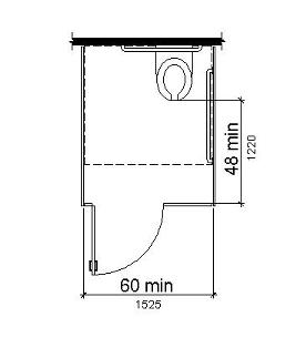
Plan view of a toilet stall with 48-inch clear space shown between the center front of the toilet bowl and the wall opposite.
Discussion: The committee intends that the toilets in the public right-of-way exceed toilet size in on-site facilities to allow scooter and larger power chair users to use these toilets. People with disabilities and people who are among the aging population use electric scooters more often in the outdoor environment than they do in the indoor environment. The 48-inch clearance in front of the toilet allows for an even longer clearance when the toilet is approached diagonally. This 48-inch clearance in front of the toilet is in addition to the clear floor or ground space required in front of the door to the toilet enclosure.
X02.3.5 Fixed tables, counters and benches
X02.3.5.1 General
Fixed tables, counters and benches shall comply with Section X02.3.
X02.3.5.2 Number and type of units to be provided
(A) Tables and counters. Where fixed tables or counters are provided in a single location, at least five percent but not less than one, shall comply with Section X02.3.5.3 for clear ground space and Section X02.3.5.4 for table and counter height.
(B) Benches. Where fixed benches are provided without tables, at a single location, at least 50 percent, but no less than one, shall have a back and armrests.
X02.3.5.3 Clear floor and ground space
For benches without tables, a clear ground space complying with proposed ADAAG Section 305 shall be provided at one end of at least one bench at each location where a single fixed bench or cluster of benches are provided. The clear ground space shall be positioned to allow a wheelchair user to be seated shoulder-to-shoulder with an individual seated on the bench. A clear floor or ground space, where required at tables and counters, shall be provided for a forward approach to the table or counter, with required knee and toe clearance, in accordance with Section 306.
EXCEPTION: When tables are provided for children’s use, a clear floor or ground space complying with proposed ADAAG Section 305, positioned for a forward approach, shall be provided. Knee and toe clearance complying with proposed ADAAG Section 306 shall be provided, except that knee clearance 24 inches (610mm) minimum above the floor or ground shall be permitted.
Discussion: The committee discussed the need for larger clear ground space in the public right-of-way. See discussion at Section X02.3.1.3.
X02.3.5.4 Height of tables
The tops of tables and counters required to be accessible shall be 28 inches (710 mm) minimum to 34 inches (865 mm) maximum above the floor or ground.
EXCEPTION: When accessible tables are provided for children’s use, the tops of tables shall be 26 inches (660 mm) minimum to 30 inches (760 mm) maximum above the floor or ground.
Figure X02.3 C Bench with Adjacent Clear Area
Bench with adjacent clear area for wheelchair user (plan view).
Figure X02.3 D Bench with Arm/Backrests
Side view of bench with arms and back.
Discussion: The committee agreed that there can be design solutions to the competing constraints of the maximum height of a leading edge detectable by cane and the minimum clear space a wheelchair user requires for knee room, and recommends future work on this issue . See frontier issue under Section X02.2.4.
X02.3.6 Bus stop pads and shelters
Bus stop pads and shelters shall comply with proposed ADAAG Chapter 10.
Discussion: A route to and into a shelter and the size of a bus stop pad for the deployment of onboard lifts and ramps are already covered by existing regulations of the US Department of Transportation, the title II regulations of the US Department of Justice, and proposed ADAAG Chapter 10.
X02.3.7 Depositories, vending machines, change machines and trash receptacles
X02.3.7.1 General
Depositories, vending machines, change machines, trash receptacles and similar fixed equipment with operable parts shall comply with Section X02.3.7.
X02.3.7.2 Fixed equipment
Where provided at a single location, at least one of each type of fixed depository, vending machine, change machine, and trash receptacle provided shall comply with proposed ADAAG Section 305, Section 308, and Section 309. The clear ground space shall not encroach into the 60-inch (1525mm) wide pedestrian access route by more than 24 inches (610mm).
EXCEPTION: Drive-up-only depositories shall not be required to comply with this section.
Advisory: **Depositories include, but are not limited to, night receptacles in banks, post office mailboxes, video stores, and libraries.
Discussion: The committee discussed the need for larger dimensions in the public right-of-way. See discussion under Section X02.3.1.3.
X02.3.8 Street identification and other pedestrian signage
X02.3.8.1 General
Street identification and other pedestrian signage shall comply with proposed ADAAG Section 703, except as noted in Section X02.3.8.3, Section X02.3.8.4, and Section X02.3.8.5. Braille signs shall comply with proposed ADAAG Section 703.5.
Discussion: The committee is recommending some provisions for tactile signage which are more stringent than in proposed ADAAG Section 703 because, in outdoor environments, touch is frequently less sensitive due to cold. The intent is to maximize legibility of tactile signs in adverse conditions.
X02.3.8.2 Types of signage
*(A) Street Identification. **Street signs shall comply with requirements of Section X02.3.8.5. Where an Accessible Pedestrian Signal is provided, visual and tactile street identification complying with Section X02.3.8.3 and Braille complying with proposed ADAAG Section 703.5 is required above the *push button.
(B) Bus route identification. Where bus route identification signs are provided in the public right-of-way on or adjacent to a public sidewalk, they shall comply with the provisions of this section for visual characters, tactile characters and Braille. Signs providing the route number and route name shall be provided. Raised print is required for route number identification only. If a variable message sign is used at a bus stop or shelter, an audible equivalent shall be provided.
Advisory:* Where street identification and other pedestrian signs, including bus route identification signs, are provided in accessible format, remote audible signs may be more easily located and more usable than tactile signs. Remote infrared audible signs (RIAS) are an excellent means of making all kinds of information accessible to persons who are blind or who have print disabilities. Requirements for RIAS are provided in Section X02.3.8.8.2.*
Discussion: Bus stops and shelters are covered as transportation facilities in accessibility guidelines adopted by DOT as part of the title II regulation (49CFR Parts 27, 37 and 38). Bus route identification signs must comply with specifications for visual characters. DOT’s ADA regulations do not require tactile signs at bus stops and shelters. DOT’s ADA regulations do require, however, that bus stop locations be audibly and visibly announced on the vehicle.
Research need: The committee believes that a system of remote audible signage utilizing emitters that can be scanned and read through personal receivers offers the greatest opportunity for making pedestrian information available to people who have vision impairments. Research in the area of accessible signage, geographic information systems, and global positioning systems is encouraged, which may result in the development of other methods of street identification and bus and bus route identification.
(C) Informational and warning signs. Informational and warning signs shall comply with requirements of Section X02.3.8.5.
Research need: While the committee believes that informational and warning signs in the public right-of-way should be provided in an accessible format, there were concerns regarding methods of making that information readily accessible to individuals who are blind or visually impaired. Signs at construction barriers were of particular concern to the committee. Research is recommended to determine whether audible and/or tactile signage is appropriate, or what other methods can be used to make informational and warning signs accessible. Research in the use of geographic information systems (GIS) should include consideration of the needs of pedestrians who are visually impaired or blind and the collection of data that could provide orientation and wayfinding information.
X02.3.8.3 Characters that are both tactile and visual
(A) Finish and Contrast.Eggshell finish shall be used for street identification and other pedestrian signage. A minimum 70 percent visual contrast is required.
Advisory:* Research indicates that signs are more legible for persons with low vision when characters contrast with their background by at least 70 percent. In general, the greater the contrast, the greater the legibility, regardless of visual acuity. Seventy percent contrast is not an optimum; it is the minimum contrast for good legibility for readers with unimpaired vision.*
(B) Character width. For pedestrian access signage, character width shall be 60 percent minimum and 100 percent maximum (3:5 minimum and 1:1 maximum) the height of the character, with the width based on the uppercase letter “O” and the height based on the uppercase letter “I.” Pedestrian signage shall be based upon the intended viewing distance in accordance with proposed ADAAG Section 703.
(C) Character height. The character height measured vertically from the baseline of the character shall be 5/8 inch minimum and 2 inches maximum based on the height of the uppercase letter “I.”
(D) Stroke thickness and cross section. Characters shall have a rounded or trapezoidal cross section. The stroke thickness of the uppercase letter “I” shall be 10 percent minimum and 30 percent maximum of the height of the character measured at the base of the cross section. Stroke thickness at the top of the cross section shall be 15 percent maximum of the height of the character.
(E) Sign Corners. All signs intended for touch reading shall have rounded corners.
**Discussion: **The above requirements are in addition to, or instead of, the requirements in proposed ADAAG Section 703. Some of the requirements are more stringent than those in proposed ADAAG Section 703. Tactile characters that are rectangular in cross section tend to be sharp and uncomfortable for touch reading. Characters that are intended for both visual and tactile reading are likely to use the widest permissible stroke width for greatest visibility, which will be less legible for touch readers than narrower stroke widths. Characters having rounded or trapezoidal cross sections are narrower at the top (tactile reading) surface than at the bottom, making them more legible to touch readers. Proposed ADAAG Section 703 permits characters that are rectangular in cross section. They are not recommended here because they are less comfortable and less legible.
A sign usable for touch reading should not have sharp corners that can injure the fingers that must find and read them. A requirement for rounded corners was also not previously addressed in ADAAG.
X02.3.8.4 Tactile characters
**(A) Character width. **Character width shall be 60 percent minimum and 100 percent maximum (3:5 minimum and 1:1 maximum) the height of the character, with the width based on the uppercase letter “O” and the height based on the uppercase letter “I.”
(B) Character height. Character height measured vertically from the baseline of the character shall be 5/8 inch minimum and 3/4 inch maximum based on the height of the uppercase letter “I.”
(C) Stroke thickness and cross section. Characters shall have a rounded or trapezoidal cross section. The stroke thickness of the uppercase letter “I” shall be 10 percent minimum and 30 percent maximum of the height of the character measured at the base of the cross section. Stroke thickness at the top of the cross section shall be 15 percent maximum of the height of the character.
(D) Sign corners. All signs intended for touch reading shall have rounded corners.
Discussion: The committee agreed with most of the requirements in proposed ADAAG Section 703.3 for tactile characters. They recommend the substitute requirements above for Section 703.3.2.3, Section 703.3.2.4, and Section 703.3.2.5, as discussed above. They added a requirement regarding rounded sign corners.
Figure X02.3 E Tactile Character Section
Diagrammatic section of a tactile character illustrating rounded and trapezoidal edges.
X02.3.8.5 Visual characters
Visual characters shall comply with proposed ADAAG Section 703.4, except the requirement in Section X02.3.8.5 (A) shall replace the requirement in proposed ADAAG Section 703.4.1.
(A) Finish and contrast.Eggshell finish shall be used for street identification and other pedestrian signage. A minimum 70 percent visual contrast is required
(B) Character height. The height of characters used in street identification and other pedestrian signage shall be based upon the intended viewing distance in accordance with proposed ADAAG Section 703.
Advisory: **This section pertains to signage that may be intended to be read from the far side of the intersection. Use of larger signs and shapes than those required in ADAAG Table 703.4.2.4 is encouraged.
Discussion: Requirements of proposed ADAAG Section 703 for visual characters, except for those for finish and contrast, were considered appropriate by the committee. Viewing distances in the public right-of-way may be further than typical indoor situations, accordingly, character height may need to be larger to result in equivalent legibility.
X02.3.8.6 Sign mounting locations
(A) Mounting height. Mounting height for all signs that include tactile characters shall be 60 inches (1525 mm) above the finish floor to the centerline of the sign.
(B) Locations.
- Bus shelters. Bus shelter signage shall be mounted on the shelter wall closest to the front of the bus, as close to the street as possible, at 60 inches (1525 mm) above the adjacent clear landing.
- Bus stops. Bus stop signage where no shelter is present shall be mounted on the pole at 60 inches (1525mm) above adjacent grade.
Figure X02.3 F Bus Shelter Signage
Isometric view of a bus shelter indicating the location of accessible signage at the leading (front) end of the side wall at the end where the front of the bus will stop.
X02.3.8.7 Changeable message signs
(A) Viewing distance.Changeable message signs presented using LED, LCD, flip-dot or other means shall be legible from the same distance as conventional print signs.
Advisory: The information in this section is provided in an effort to improve the readability of changeable or variable message signs for pedestrian users of the public right-of-way. Character height for changeable message signs should be about 35 percent greater than character height for conventional print signs in order to have equal legibility at the same distance. Characters should be uppercase, and in conventional form. Characters should not be italic, oblique, script, highly decorative, or of other unusual forms. Character width should be no less than 60 percent the height of the character. Characters having a single stroke width have been found to be more legible at 2-inch character height than characters having double stroke width. Characters having a double stroke width have been found to be more legible at 4-inch to 8-inch character height. Spacing between individual characters should be 1.5 to 2.0 times stroke width for greatest legibility.
(B) Message flow. Messages that are short enough to fit within the length of a changeable message sign should be static. Where messages are too long to fit within the length of a changeable message sign, messages shall stream with a dwell time of 2.74 seconds. Paging messages are not permitted.
**Advisory: **Static messages have been found to be more legible than dynamic messages to readers having visual acuities from 20/20 to 20/200. They are also greatly preferred. Dynamic messages that stream from right to left have been found to be significantly more legible than messages that page up from the bottom.
Research need: Research is needed to determine specifications for changeable message signs that will result in equivalent legibility for readers having visual acuities from 20/20 to 20/200, in outdoor situations. Technical specifications are needed for changeable message signs of different types and colors, in situations in which messages are either static or dynamic, and in situations in which either the viewer or the sign are in motion.
X02.3.8.8 Audible Signs
(A) General. Where there are audible signs, a visual equivalent shall be provided.
(B) Requirements for Remote Infrared Audible Sign (RIAS) Receivers.
- Where personal receivers are used to make information on signs accessible to persons who are blind or who have print disabilities, basic speech messages shall be frequency modulated at 25 kHz (+/- 10 percent deviation), and shall have an infrared wavelength from 850 to 950 nanometer (nm).
- Receiver shall produce a 12 decibel (dB) signal-plus-noise-to-noise ratio with a kHz modulation tone at +/- 2.5 kHz deviation of the 25 kHz subcarrier at an optical power density of 26 picowatts per square millimeter measured at the receiver photosensor aperture.
- The audio output from an internal speaker shall be at 75 dB(A) minimum at 18 inches with a maximum of 10 percent distortion.
- The receiver photo sensor aperture shall be 80 degrees in acceptance angle.
-
The receiver shall be designed for a high dynamic range and capable of operating in full-sun background illumination.
- Capture of the receiver by the stronger of two signals in the receiver field of view requires a received power ratio on the order of 20dB for negligible interference; adjacent transmitter frequency tolerance of 50 Hz to 100 Hz improves the intelligibility of interfering signals.
Advisory:* Transit stations and platforms are routinely used by persons who are blind. Tactile signs do not necessarily help persons who are blind to locate station entrances and exits, fare gates, fare machines, stairs and escalators, platforms, and other amenities, because tactile signs cannot be located consistently enough for persons who are blind to find them efficiently. Remote infrared audible signs are suggested as a wayfinding system because, like vision, they enable users to scan the environment (using a personal receiver) and “read messages” from a distance. They are able to provide directional and informational messages in a way that enables persons who are blind to travel as independently as persons who can read print signs.*
Discussion: Remote infrared audible signs (RIAS) have been found to be a particularly effective means to make wayfinding information accessible to persons who are blind or who have print disabilities. Many transmission media are potentially available for use in communicating wayfinding information to people with print-reading disabilities (e.g., blindness, low vision, dyslexia, and mental retardation). A key concern at this stage of technology development is the possibility of blocking the development of new technologies by inadvertently limiting compliance to existing technologies.
Discussion: Currently, there is a need to provide a uniform protocol for communication of information by RIAS so that:
- Users will not be required to carry more than one receiver (one for each wayfinding application) to acquire basic wayfinding information;
- Users will be able to use the same receiver in any location (within or between cities) so that the wayfinding environment is “seamless”;
- Manufacturers will be able to design basic functionality around a single communication protocol. Additional enhancements would be permitted.
- Manufacturers and users will be able to take the protocol specifications to national and international standards groups. Registering the protocol would help provide a clear channel (free from interference from competing communication technologies and interfering signals from other electronic devices and systems).
- Protocol must be coordinated with existing assistive listening device systems to ensure simultaneous systems operations without disruption.
X02.4 Sidewalk/Street Transitions
X02.4.1 General
Sidewalk/street transitions, curb ramps, transition ramps, and landings in the public right-of-way shall comply with Section X02.4.
Discussion: In keeping with a “kit of parts” approach, the committee recommends new names for the parts of the system that transition from roadway to public sidewalk level. The new terms identify function rather than geometric orientation of the ramp. Curb ramps cut though the face of the curb, and may or may not be perpendicular to the curb line. Transition ramps transition between upper and lower landings within the public sidewalk. Some transition ramps are used to allow the public sidewalk to dip down at driveways, at intermediate locations in the block.
By using this flexible kit of parts, designers can create access between public sidewalk and roadway level with a combination of approaches.
X02.4.1.1 Where required
A curb ramp or flush landing shall be provided wherever the pedestrian access route crosses a sidewalk/street transition, including intersections, mid-block crosswalks, medians and islands traversed by crosswalks, alleys, accessible parking aisles, passenger loading zones, and locations where the public sidewalk ends and pedestrian travel continues in the roadway.
EXCEPTION: A curb ramp or flush landing is not required where the pedestrian access route crosses a driveway and the elevation of the pedestrian access route is maintained.
X02.4.1.2 Corners
At any intersection in the public right-of-way that has at least one corner served by a public sidewalk or a pedestrian access route, all corners of the intersection served by a crosswalk shall have curb ramps or flush landings.
Figure X02.4 A Curb Ramp
Curb Ramp: isometric view of a curb ramp as currently defined. The illustration is based on the old “perpendicular” style ramp.
Figure X02.4 B Transition Ramp
Transition Ramp: isometric view of a transition ramp as currently defined. The illustration is based on the old “parallel” style ramp.
Figure X02.4 C Shared Curb Ramp
Shared ramp shows a single ramp used for two crossing directions.
Figure X02.4 D Combination Assemblies
The top one shows an assembly that might be used at a mid-block crosswalk, and combines transition ramps leading to a landing and from there access to a single curb ramp at right angles to the transition ramps. The bottom one shows a corner where the sidewalk is dropped by transition ramps to a lowered elevation, from which two separated curb ramps provide access to the street.
Figure X02.4 E Projecting Curb Ramps
The top diagram shows a built-up curb ramp entirely beyond the curb line with a note that this arrangement is not to be used in traffic lanes. The lower diagram shows a curb ramp that projects partially beyond the curb line.
Figure X02.4 F Shared Flush Landing
Shared Transition: a combined approach with two transition ramps on a curved corner approaching a single landing area that is blended with the vehicular way.
Discussion: The committee concurred that curb ramps or flush landings were required at every corner, to eliminate the possibility of a pedestrian entering a road, traveling across the road, then finding no refuge at the other end of the crosswalk. The intent is that there be, at minimum, a landing at each corner, either at roadway level (flush landing) or sidewalk level (behind a curb ramp). If there are two curb ramps or flush landings placed on an otherwise undeveloped corner, they should be connected to each other and to any pedestrian call button, so that a pedestrian can have a refuge while deciding whether to continue on the shoulder or turn around.
X02.4.1.3 Number
Where curb ramps or flush landings are required, there shall be a separate curb ramp or flush landing serving each direction of travel, whenever technically feasible.
Discussion: The committee strongly discourages the use of shared curb ramps, formerly called diagonal curb ramps, or shared flush landings , formerly called single parallel curb ramps, unless there is no alternative. No specific exceptions were agreed upon. The committee clearly did not want jurisdictions to use shared curb ramps or flush landings as a matter of course, simply because they are cheaper to install. Some of the reasons against shared curb ramps and shared flush landings are:
- Shared curb ramps directionally align the traveler out of the crosswalk and potentially into moving vehicular traffic. To stay within the limits of the crosswalk, wheelchair users that follow the path of the shared ramp must decrease travel speed to make a turn at the bottom of the ramp. The loss of momentum due to the turn requires the traveler to exert more effort to travel across the crosswalk.
- Persons approaching a shared curb ramp from within a crosswalk must decrease travel speed and make a turn to align with the ramp. With the loss of momentum, additional effort is necessary to climb the ascending grade of the ramp.
- Visually impaired pedestrians, even when warned not to rely on the directionality of the curb ramp, may inadvertently travel directly into the path of moving vehicles if other directional cues are not present.
- For all pedestrians, travel distance and travel time are greater at intersections that use shared curb ramps on the midpoints of a curb return. Individual curb ramps that are aligned with the path of travel decrease travel time and distance.
- Drivers may not expect pedestrians entering the traveled way at a point not centered on the crosswalk. If the pedestrians are visually impaired, of short stature, or in wheelchairs, they may not be noticed by inattentive drivers.
- A single curb ramp or flush landing generally precludes the use of two, widely spaced, easy to distinguish, accessible pedestrian signal call buttons.
The committee recognized that intersection geometry can preclude the placement of separate curb ramps or flush landings for each crosswalk. The combination of such variables as curb radius, sidewalk width, and furnishing zone width, create situations where shared curb ramps or flush landings are the only possible alternative. Some examples are:
- A corner with a curb return radius that is so large that the crosswalks meet at the midpoint of the curve.
- A corner where placing two curb ramps or flush landings would result in them being located outside the crosswalk markings, or would result in stop bars placed too far back on the side street for driver safety or pedestrian safety.
- An intersection that is skewed, such that two curb ramps or flush landings will not fit in the acute angle corners.
- An alteration, where the corner has retaining walls, buildings, or other barriers that are technically infeasible to relocate.
- An intersection in which one street has an unavoidably steep grade, and a shared curb ramp or flush landing at the midpoint of the curb return may have less severe warp than a curb ramp or flush landing closer to the tangent of the steep street.
- An intersection in an area of steep terrain, where both streets are flattened to allow for acceptable crosswalk slopes. It may be feasible to flatten a small intersection area and provide accessible crosswalks leading to a shared ramp. Placement of a pair of curb ramps would necessitate a larger flattened area, resulting in steeper sidewalks between intersections.
Where the above conditions exist, designers are encouraged to try to reduce the curb radius or take other measures to eliminate the need for shared curb ramps or flush landings.
There are some situations in which a shared curb ramp or flush landing can be made extra wide, thereby enabling it to serve both directions of travel without deflecting the pedestrian into the parallel vehicular pathway. The problems of longer crossing distances and unexpected pedestrian departure points may still exist. Such situations include:
- Fully depressed corners.
- Flush landings large enough such that pedestrians can easily line up with either direction of travel, and such that accessible pedestrian signal call buttons can be spaced properly.
- Corners where there is basically a flush transition for the full length of the curve.
X02.4.1.4 Landings
There shall be a landing at the top of each curb ramp. There shall be a landing at the top and at the bottom of each transition ramp. At each sidewalk/street transition where a curb ramp is not needed (for example , where the sidewalk elevation is dropped to roadway elevation), there shall be a flush landing provided at the roadway level, in the pedestrian access route. Landings may overlap with adjacent landings or a single landing may serve multiple ramps.
EXCEPTION: Where the public sidewalk or pedestrian access route elevation is lowered to cross an unsignalized driveway, landings are not required. However, successive curb ramps or transition ramps shall be separated by at least 60 inches (1525mm) in the direction of travel on the pedestrian access route.
Discussion: Landings are needed in public sidewalks before pedestrians cross into the roadway, even if the public sidewalk and the roadway are at the same elevation. Landings are unobstructed level areas used for turning (including U-turns), accessing pedestrian signal call buttons, resting, passing, and waiting for a safe crossing time.
There was considerable debate about the recommendation to require landings at the top of transition ramps. The vote on this recommendation was very close. The rationale for requiring a landing is to provide a place for a pedestrian to rest after climbing the ramp, before attempting a steep sidewalk grade. However, in steep terrain such a landing may have the effect of making the sidewalk even steeper. Where the roadway grade is more than about five percent and the sidewalk is immediately adjacent to the curb, placing a landing at the top of transition ramps may be technically infeasible.
The committee found that an exception to the landings requirement was necessary for some types of driveways that cross public sidewalks. The exception is limited to driveways that lower the sidewalk elevation across the driveway opening. In many locations, it would be difficult to make the sidewalk relatively flat at each driveway. Since the pedestrian is traveling on a public sidewalk, and a driveway is a crossing of a public sidewalk, the pedestrian retains the right-of-way over the vehicle. The pedestrian is not required to stop and wait for vehicles, therefore the landing is not necessary. However, at signalized driveway crossings, where traffic volumes are greater and pedestrians are compelled to wait to cross, a landing is required for pedestrian safety.
X02.4.2 Placement
Curb ramps, transition ramps, flush landings and maneuvering spaces shall be placed in accordance with this section.
X02.4.2.1 Street interface
The bottom of the curb ramp run, exclusive of flares, shall be wholly contained within the markings of the crosswalk or access aisle that the curb ramp serves and may not protrude beyond the curb line into the path of vehicles. Beyond the curb line, there shall be a minimum maneuvering space of 48 inches by 48 inches (1220 by 1220mm). The maneuvering space shall be wholly contained within the crosswalk and shall be wholly outside the parallel vehicular travel path. Where flush landings are provided, they shall be placed so that the expected path of a pedestrian entering the crosswalk or access aisle is wholly contained within the crosswalk or access aisle and wholly outside the parallel vehicular travel path. At passenger loading zones, the curb ramp or flush landing shall be placed in accordance with section Section X02.6.3.
EXCEPTION: A curb ramp may project into an accessible parking aisle if the ramp does not intrude into maneuvering and unloading areas.
Discussion: Flush landings are sometimes larger than the crosswalk, especially if a single flush landing is shared between two crossing directions. The landing and crosswalk must be oriented to each other such that a pedestrian can wait at the landing, oriented in the direction of the crosswalk, and enter the crosswalk when safe to do so.
When a curb ramp is placed at a slight skew to the crosswalk, the same problems of turning and orienting occur as discussed above in the proposed rule relating to shared curb ramps. The crosswalk must be wide enough to allow for maneuvering at the curb ramp departure without entering parallel vehicular traffic. The maneuvering space of 48 inches by 48 inches is not technically a landing, because the slope in the roadway may exceed 1:48, but it serves the purpose of providing space for the pedestrian using a wheelchair or other mobility aid to align properly with the curb ramp.
Curb ramps that project into the vehicular travel path are prohibited because they are a hazard to pedestrian and vehicular travel. Projected curb ramps may result in ponding of storm water and the accumulation of ice.
X02.4.2.2 Sidewalk interface
Curb ramps shall be wholly contained within the public sidewalk.
X02.4.3 Directionality
RESERVED.
Advisory: The curb ramp should generally align with the expected path of travel to provide directionality, provided that the cross slope of the ramp does not exceed 1:48.
Figure X02.4 G Curb Ramp Directionality
Illustration of a curb ramp that exhibits directionality to the crosswalk and the sidewalk, while complying with warping and cross slope requirements.
Discussion: The committee strongly supported both the idea of aligning curb ramps with the direction of the crosswalk (directionality) and minimizing the problems for wheelchairs that are caused by skewed approaches, warping at the foot of the curb ramp, or cross slope in the curb ramp. Recognizing that the ideal cannot always be achieved, the committee supported directionality, but not at the expense of excessive cross slope and warping.
Blind and visually impaired pedestrians use several different cues to align themselves with the crosswalks at intersections. One cue can be to determine the alignment of the curb ramp by its falling grade to the roadway. When the curb ramp is aligned with both the sidewalk and the crosswalk, visually impaired pedestrians have a straight line of travel. The straight line of travel usually dictates that the ramp cross the corner radius at a skew.
However, ramps that cross the curb at a skew may cause a wheelchair to become unbalanced. The cross-slope of the ramp, the gutter grade, the street crown grade, and the skew angle of the ramp all combine to cause one or two of the wheels of a wheelchair to lift from the ground surface. With one or two of the wheels in the air, the chair user experiences some loss of control until the wheelchair again finds four points of support. The instability problem can be minimized by having the wheelchair cross the curb at a right angle. This requires a radial alignment of the curb ramp.
The committee found that the needs of both visually impaired and wheelchair travelers could be generally be satisfied in only two situations: very flat intersections or corners with a very small radius.
Intersections at or below two percent grade in all directions would allow the construction of ramps that entered the street with little or no cross-slope. The instability problem for wheelchair users would be minimized since there would be no warp in the curb ramp and there would be no counterslope problems between the ramp and the street grade. The ramps could be aligned with the direction of travel minimizing changes of direction for the visually impaired.
Corners with very small corner return radii have straight sections of curb within the corner area that can accommodate curb ramps which are both directional and perpendicular to the curb line. However, the committee recognizes that the use of small corner return radii can affect vehicle turning movements and that this solution will not be appropriate in all cases.
Research need: The committee identified a need for additional information and research on the use of tactile cues for directionality that do not rely on the curb ramp direction. A number of possible strategies to provide directional and alignment information to individuals who are blind or visually impaired were considered by the committee. These included tactile guidestrips, directional bar tiles, alignment of the detectable warning, and raised crosswalk lines. Tactile guide strips have been used in some locations in San Diego and San Francisco. These have been constructed of metal, concrete, or plastic and embedded in the street in the center of the crosswalk area. Directional bar tiles have lozenge shaped raised sections (similar in height to the truncated domes of detectable warnings) intended to be oriented in the direction of travel. These are used in England, Sweden and Japan. Raised crosswalk lines were also suggested, with photos presented of an example using concrete tiles to outline the crosswalk as well as a discussion of the use of thermoplastic markings. However, concerns regarding detectability and maintenance were raised, as well as concerns about the impact of such surfaces on wheelchair users.
X02.4.4 Width
The clear width of a curb ramp run shall be not less than 48 inches (1220mm), excluding flares. The clear width of a transition ramp shall not be less than the width of the pedestrian access route.
Discussion: Recognizing that the curb ramp can be a bottleneck to pedestrian flow, the minimum clear width of four feet matches the minimum 48-inch width of the pedestrian access route in several areas where exceptions to the 60-inch width are permitted. Wheelchair bases have gotten wider in recent years and three-wheeled scooter use has become more prevalent. In addition, the wider curb ramp widths allow for some wheelchair maneuvering on the curb ramp to adjust for approaching curb ramp bottoms that are skewed. Where possible, a wider ramp with a 60-inch width is encouraged to allow for two wheelchairs to pass, particularly in areas where higher wheelchair usage is prevalent. In the past, wider curb ramps raised some concern because the width of depressed curb might confuse a blind pedestrian. With the inclusion of detectable warning surfaces (see Section X02.5.7) at the foot of curb ramps, this concern is no longer significant.
Transition ramps must be the width of the entire pedestrian access route to accommodate all pedestrian traffic wishing to enter the street. Since they do not have flared sides, transition ramps could introduce a tripping hazard or be undetected by pedestrians with low vision if they are not the full width of the public sidewalk. Unlike curb ramps, which can be used selectively by those pedestrians that prefer them, a transition ramp is generally used by all pedestrians. Therefore, it should be wide enough to allow for pedestrians that travel with a service animal or a pedestrian guide, and still allow for pedestrian traffic in the opposite direction to pass.
X02.4.5 Landing size
Landings, including flush landings, shall have a minimum clear dimension of a 60-inch by 60-inch (1525 by 1525mm) square or 60-inch diameter circle. Landings may overlap with adjacent landings or a single landing may serve multiple curb ramps or transition ramps. Landings may overlap with the clear ground or floor space required at push buttons.
Discussion: Landings provide the clear level space at the top of the curb ramp, or flush with the street behind the sidewalk/street interface, that allow space for the user to maneuver and wait. Minimum landing dimensions are derived from the need to provide a five-foot diameter turning circle. Landings need to be positioned at locations that provide the user with directional choices or where the user must wait for a suitable time to cross the street. As with the width of curb ramps, landing dimensions must provide for turning and maneuvering needs of three-wheel scooters, which have longer turning radii than wheelchairs. Landings are critical to maneuvering at curb ramps, and they allow for passing between two wheelchairs or scooters. Landings may also provide access to pedestrian signal call buttons, and must be large enough so that the pedestrian can approach the button, operate it, leave the button, and orient to the crosswalk while awaiting the signal. All of this must occur on an unobstructed level surface.
Utility supports and other obstructions may not be located within the minimum clear landing dimension or the clear space approach to the pedestrian signal call button.
Flush landings provide a clear level space on the sidewalk, prior to entering the street, for the user to maneuver or wait.
X02.4.6 Running grade
The maximum running grade of any portion of any curb ramp or transition ramp shall be 1:12 as measured from a level plane.
EXCEPTION: Curb ramps and transition ramps are not required to be longer than 15 feet.
Discussion: On streets where grades are steep and it is difficult or impossible for the transition ramp or curb ramp maximum slope of 1:12 to intersect the street grade, a steeper grade may be used to limit the run to 15 feet in length. It should be noted that the limit proposed in the Interim Final Rule was 96 inches, which applied only to parallel curb ramps (transition ramps in this document). The 15 foot maximum proposed here is an attempt to find a reasonable compromise between what is accessible and what is technically feasible in the case of steep grades.
The committee discussed the fact that there are situations where a curb ramp or transition ramp would need to be greater than 15 feet in order to achieve the 1:12 grade and it would not be difficult to do so because the grade of the terrain or adjoining roadway is not steep. One example is where the sidewalk elevation is 15 inches or more above the street. Where the construction of a curb ramp or transition ramp longer than 15 feet is possible, the 15-foot limitation should not be invoked to create unnecessarily inaccessible sidewalks. The committee agreed that the limitation should apply only to curb ramps or transition ramps adjacent to roadways or terrain having a grade greater than a certain percentage, but, due to insufficient time for consideration, did not determine what that percentage should be.
X02.4.7 Cross slope and warp
The maximum cross slope of curb ramps and transition ramps, measured perpendicular to the direction of travel, is 1:48. The maximum cross slope at landings is 1:48 in any direction. Surfaces shall generally lie in continuous planes with a minimum of surface warping.
EXCEPTION: Where the base of the curb ramp or the edge of the flush landing must join a street with a running grade greater than 1:48, the base of the curb ramp or the edge of the flush landing may be warped to meet the street running grade.
Discussion: Generally, with the limitation of 1:48 on crosswalk cross slope, warping will not be required in new construction. The committee found that the planar surfaces, those with little to no warping, would ensure that all wheels of a wheelchair would be in contact with the travel surface. For the wheelchair user, the planar surface yields the highest possible degree of stability and mobility. The committee also recognized that warping of ramp surfaces will be a factor in both new construction and certainly in alterations.
Research need: Research is needed to indicate what maximum warp condition can be tolerated without causing a tipping hazard for pedestrians using wheelchairs, scooters, walkers or other mobility aids. Research is also recommended to develop design alternatives to minimize adverse effects on wheelchair travel from surfaces that are warped.
X02.4.8 Counter slopes
The grade break between the counter slopes of gutter and/or road surfaces within 24 inches of the curb ramp and the running grade of the curb ramp shall not exceed the algebraic difference of 11 percent. If two or more plane changes are present, they shall be separated by 24 inches (455mm).
Figure X02.4 H Counter Slope Conditions
Sectional view of wheelchair at a counter slope condition with grades indicating the algebraic differences and limitations. Second view showing double grade break.
Discussion: Gutter counter slope is the angle point or grade change where the down slope of the curb ramp meets the up cross slope of the gutter. Steep counter slopes will cause some wheelchairs to catch on back rollers and lose drive wheel traction. For others, the steep counter slope will catch footrests. Many road standards set a standard gutter cross slope at 5 percent. The committee voted to set the maximum grade change at 11 percent to avoid causing problems for some wheelchair users. The committee did consider other alternatives, including maintaining the current 13.33 percent, however due to insufficient data, the committee felt that the flatter 11 percent standard would be safer. If the curb ramp is set at 1:12 (8.33 percent) and both were built to maximum standard, then the resulting algebraic difference in grade would be 13.33 percent. Consequently, gutter cross slope may need to be lessened at intersections or other locations where curb ramps are placed. Also, this standard could be met by lessening the grade of the curb ramp.
Some members felt that the existing 13.33 percent limit would be adequate if constructed properly and that more enforcement, rather than stricter requirements, was necessary. Other members suggested that more research on riding surface angles and clearances under the wheelchair footrest were necessary. Some members felt that wheelchair designers and manufacturers had some obligation to produce wheelchairs that would accommodate the users needs and have the ability to safely operate in a street environment. Some recent innovations in the caster wheel design do show some promise in making wheelchairs better at negotiating grade changes.
X02.4.9 Edge conditions
The edges of the public sidewalk shall comply with the requirements of this section.
X02.4.9.1 Flares
Curb ramps located where pedestrians may walk across the curb ramp shall have flared sides. The length of the flares shall be at least ten times the curb height, measured along the curb line. Curb ramps with returned curbs shall be permitted where pedestrians would not normally walk across the curb ramp. Where a sidewalk splits, and only part goes down a transitional ramp, the split edge shall be protected with landscaping, railings, or other fixed barriers. Curbs may be used to separate landscaping or other features from landings but should not be placed so as to block permitted travel to an unimproved surface.
Discussion: Notice that the slope of the flare is 1:10 relative to the plane of the curb, not to a level plane. In the public right-of-way, flares are not considered a part of the pedestrian access route. The 1:10 slope relative to the plane of the sidewalk is sufficient to avoid a tripping hazard, and allows the flares to be built symmetrically, even on sloping terrain. The majority of curb ramps are already built this way.
Since there is a mandatory 60-inch top landing at each curb ramp, there is no need for the ADAAG provision for 1:12 slopes on flares where the width of the walking surface at the top of the curb ramp run is less than 48 inches.
Figure X02.4 I Sloped Curb Ramp Sides
Isometric view of curb ramp with sloped sides describing the required length of the slope and measurement method (10x the curb height, measured at the face of the curb).
X02.4.9.2 Curb returns
Curb ramps with returned curbs shall be permitted where pedestrians would not normally walk across the curb ramp.
Discussion: Flares are not necessary where pedestrians would not be expected to cross the edges of curb ramps, such as in medians or where there is landscaping or a fixed obstruction blocking such circulation.
X02.4.9.3 Diverging grades
Where a public sidewalk diverges, with only part becoming a transition ramp, the area where the surface grades diverge shall be protected with clearly defined surfaces such as landscaping, railings, or other fixed barriers.
X02.4.9.4 Curb placement
Curbs may be used to separate landscaping or other features from landings but should not be placed so as to block permitted travel to an unimproved surface.
Discussion: At some corners, there is an improved sidewalk entering from one direction, and an unimproved pedestrian path behind the curb entering from the other direction. The landings should not be built with curbing around the back that would be a barrier to travel on the unimproved surface.
X02.4.10 Surfaces
The surface of curb ramps and landings shall be stable, firm and slip resistant and shall lie generally in a continuous plane with a minimum of surface warping. Gratings, access covers and similar surfaces shall not be located on curb ramps, transition ramps, landings, or gutter pans at the sidewalk/street transition.
Discussion: The surface requirements for curb ramps and landings in the public right-of-way are consistent with the surface requirements in proposed ADAAG.
X02.4.11 Vertical grade breaks and lips
There shall be no vertical change in level on a curb ramp or transition ramp, on a flare, in a landing, in the gutter pan at a sidewalk/street transition, or between curb ramps, flares, landings, gutter pans, and adjacent public sidewalk and road elements.
Discussion: This proposed standard prohibits vertical changes in level in other transitional areas such as flare/ramp, flare/sidewalk, ramp/landing, ramp/sidewalk, landing/sidewalk, and gutter/pavement. All connections must be flush, within reasonable construction tolerances.
Vertical changes in level at the base of curb ramps and landings , called “lips”, have long been used to control drainage at curb ramps. However, since these lips create only a minimal vertical face, they are relatively ineffective in preventing storm water runoff in the gutter from impacting the curb ramp. When the front caster wheels of a wheelchair contacts a gutter lip, the caster wheels may be deflected and quickly stop the chair. Depending upon the velocity at the time of contact, the user may be thrown forward from the wheelchair. The degree of stormwater channelization provided by a drainage lip is not sufficient to offset the hazard it creates for pedestrians with disabilities.
**Research need: **Research is needed to develop design alternatives to minimize the adverse effect on wheelchair travel of surfaces that contain grade breaks.
X02.4.12 Detectable warnings
Sidewalk/street transitions shall have a detectable warning complying with Section X02.5.7.
EXCEPTION: Detectable warnings shall not be provided where the sidewalk/street transition occurs at an unsignalized driveway.
Discussion: The committee recognized that some currently manufactured detectable warning products cannot be installed on warped surfaces or surfaces with grade breaks. The industry will need to accept the challenge to develop detectable warning surface materials that will be usable in non-planar applications.
X02.4.13 Vehicular obstructions
Curb ramps and flush landings shall be located or protected so that legally parked vehicles do not obstruct the pedestrian access route.
Discussion: It was agreed that there is a need for a provision related to preventing the obstruction of the pedestrian access route by legally parked cars. The recommended provision is consistent with Interim Final Rule section 14.2.4. Public agencies should consider lengthening the no parking zone adjacent to a crosswalk, since wheelchair users and people of short stature may be hidden from a motorist’s view by parked cars.
X02.4.14 Curb type
Reserved.
Frontier issue: The committee discussed and wishes to add the following proposal to the list of frontier issues: To aid in the protection of all pedestrians at intersection corners, and to make intersection geometry more cane detectable, the committee suggests that where rolled or “rollover” curb sections are proposed in new construction, a transition be provided from the rolled curb section to a barrier or vertical curb section of at least the same height and running the entire return of the curb return, and within 10 feet of the edge of each curb ramp (excluding flares) or the flush street transition.
X02.5 Pedestrian Street Crossings
X02.5.1 Pedestrian signal push buttons
X02.5.1.1 General
Where new traffic signals with pedestrian controls are installed, they shall comply with this section.
X02.5.1.2 Features
Push buttons shall have the following features.
(A) Size. Push buttons shall be a minimum of 2 inches (51mm) across in at least one dimension.
(B) Maximum force. The force required to activate push buttons shall be no greater than 3.5 pounds (15.5N).
**(C) Operation. **Push buttons shall be operable with a closed fist.
(D) Locator tone. There shall be a locator tone complying with X02.5.1.5.
(E) Visual contrast. Push buttons shall have a visual contrast with the body background of at least 70 percent.
(F) Indicator. There shall be a visible and audible indicator that the button press has occurred.
Advisory:* A long button press (e.g., 3 seconds) may bring up the accessible features or additional accessibility features of the individual device. An additional button should not be used to bring up additional accessibility features. All accessible features available are to be actuated in the same way. Thus, for a given signal, a long button press could request more than one additional feature. Possible additional features include: 1) sound beaconing by increasing the volume of the WALK tone and the associated locator tone for one signal cycle, so a blind pedestrian might be able to use the sound from the opposite side of the street to provide alignment information; 2) sound beaconing by alternating the audible WALK signal back and forth from one end of the crosswalk to the other; 3) providing extended crossing time; and 4) providing a voice message with the street names at the intersection.*
(G) Signage. Signage accompanying push buttons shall comply with Section X02.5.1.4.
Discussion: These specifications are intended to make pedestrian push buttons accessible. The recommended change to a reduced maximum operating force is based in part, on the preamble to proposed ADAAG309 Operable Parts (p 62262, 2nd col): “Information indicates that most control buttons of keys can meet a 3.5 maximum pounds of force and a maximum stroke depth of 1/10 inches.” The closed fist requirement is based on the Access Board’s design guidelines: “Devices that can be operated by a closed fist acting on any point on the surface will be most usable by pedestrians who have mobility impairments.” The provision of visual contrast and a locator tone enable blind or visually impaired pedestrians to locate the push button. The visible and audible indicator informs both visually impaired and sighted individuals that the request for a walk signal has been received.
X02.5.1.3 Push button location
The location of push buttons shall be in accordance with the following minimum requirements.
(A) Adjacent to landing. The push button shall be mounted adjacent to a clear ground space or a landing on the pedestrian access route leading to the crosswalk. The clear ground space shall be at least 32 inches by 54 inches (815 by 1370mm), shall slope no more than 1:48 in any direction, and shall be provided with a stable, firm and slip resistant surface from which to operate controls. This clear ground space may overlap entirely with the pedestrian access route.
(B) Proximity to approach. Where a parallel approach to the push button is provided, controls shall be within 10 inches (255 mm) of the clear ground space, measured horizontally, and centered on it. Where a forward approach is provided, controls shall abut and be centered on the clear ground space.
(C) Direction of control face. The control face of the push button shall be parallel to the direction of the crosswalk controlled by the push button, and no closer than 30 inches (760mm) to the curb line.
(D) Mounting height. The centerline of the push button shall be mounted 42 inches (1070mm) above the clear ground space for approach.
(E) Close to crosswalk. The push button shall be mounted no further than 5 feet (1.5m) from the extension of the crosswalk lines, and within 10 feet (3m) of the curb line, unless the curb ramp is longer than 10 feet (3m).
*(F) Proximity to curb or transition ramp. **When located at a curb ramp, the push button shall be placed within 24 inches (610mm) of the top corner of the curb ramp, on the side furthest from the center of the intersection of the roadway. When located at a *transition ramp, the push button shall be placed adjacent to the lower landing.
Advisory: It should be noted that for information in vibrotactile format to be useable, the pole must be located so the user is able to keep a hand on the button while aligned at the top of the curb ramp or at the crosswalk. Note: vibrotactile information alone is not allowed.
(G) Separation. Where there are two accessible pedestrian signals on the same corner, the push buttons shall be mounted on poles separated by at least 10 feet (3 meters).
EXCEPTION: If the requirement for separation cannot be met due to location requirements (A) through (G), two accessible pedestrian signal-related push buttons may be installed on a single pole. If installed on the same pole, the APS must be equipped to provide speech-transmitted data or other technology that delivers an unambiguous message about which crosswalk has the walk signal indication.
Figure X02.5 A Curb Ramp APS Zones
Curb ramps at an intersection with APS zones indicated in plan.
Figure X02.5 B Transition Ramp APS Zones
Transition ramps at an intersection with APS zones indicated in plan.
Figure X02.5 C Shared Curb Ramp APS Zones
Shared ramp at an intersection with APS zones indicated in plan.
Discussion: Requirements for push button location were discussed in detail by the subcommittee and are essentially the same as requirements proposed by FHWA for inclusion in the Manual on Uniform Traffic Control Devices (MUTCD) in December 1999. The committee’s intent is to standardize some elements of pedestrian push button location to make the push button more accessible to pedestrians who are blind or who have vision impairments. Locating the pedestrian push buttons at some distance from the crosswalk, which is common now, makes it difficult for a pedestrian, particularly a blind pedestrian or a pedestrian using a mobility aid, to push the button and return to the crosswalk location in time for the walk phase. Users of wheelchairs and mobility aids need to be able to push the button from a level surface. The control face of the push button or the push button housing will include a tactile arrow to inform a blind pedestrian about the direction of the crosswalk, so the location and direction of the control must be aligned with the crosswalk. Since the APS will provide an audible indication of the walk interval from the pedestrian push button, the blind pedestrian must be able to discern which signal is sounding at each phase. This is much harder if both APS are on the same pole, since using only different tones to distinguish the directions is prohibited in Section X02.5.2.2 (A). The separation is intended to allow the blind pedestrian to determine which APS is sounding through sound localization while standing at the curb preparing to cross the street. While the separation is not required for call buttons that are not associated with an APS or locator tone, routinely separating the call buttons will result in a more uniform and predictable location, and will facilitate future APS and/or locator tone installation.
X02.5.1.4 Push Button Signage
(A) Tactile arrow. Where there is a push button, there shall be a tactile arrow pointing in the direction of pedestrian travel controlled by the button. The arrow shall be raised at least 1/32 inch (0.8 mm), 1 1/2 inches (38mm) in length. Stroke width shall be between 10 percent minimum and 15 percent maximum the length of the arrow. The arrowhead shall be open and at 45 degrees to the shaft. The arrowhead shall be no more than 33 percent of the length of the arrow shaft.
Advisory:If the curb ramp is not aligned with the crosswalk, the arrow will point in the direction of travel, not in the direction of the curb ramp orientation.
Figure X02.5 D Tactile Arrow
Diagrammatic view of arrow illustrating proportional relationships.
(B) Universal symbol. Controls are to include a universal tactile and visual symbol (if established by the Access Board) that will go on or at the push button indicating the presence or absence of an accessible pedestrian signal at a crosswalk.
Figure X02.5 E APS Symbol
Diagram of three Braille dots forming an equilateral triangle centered on the face of a 2” push button.
Discussion: For the universal tactile and visual symbol, the committee suggests application of three dots in a triangle on the button as close to the center as practicable.
(C) Street name. Street name information shall be provided at pedestrian push buttons. The accessible street name information provided at a pedestrian push button shall include the street name (or a reasonable abbreviation) in grade 2 Braille and in tactile raised letters complying with Section X02.3 and Section X02.5.1.4. The sign shall be located immediately above the push button mechanism and parallel to the crosswalk controlled by the button. The street name shall be the name of the street whose crosswalk is controlled by the push button.
Advisory:While this is in contrast to the convention in visual street naming, where the street name is parallel to the street itself in order to be visible to drivers and pedestrians, it is not in contrast to visual signs adjacent to pedestrian push buttons which indicate which street is controlled by the push button.
Audible signage may be provided in addition to Braille and tactile signage. Audible signage can provide auxiliary information about the intersection, which can be of great value to persons with visual impairments and to persons benefiting from redundancies.
Discussion: The arrow and street name information at the push button will provide information accessible to blind pedestrians, now typically provided to sighted pedestrians by signage, to clearly indicate which crosswalk is controlled by the push button. The arrow must be oriented parallel to the crosswalk to give this information clearly; the specifications of the arrow are to make it more easily distinguishable by touch.
(D) Crosswalk mapping. Where a map of a crosswalk is associated with a push button, the map shall be visual and tactile. Maps shall have at least 70 percent visual contrast, light-on-dark or dark-on-light. The characters and/or symbols shall be raised 1/32 inch (0.8mm) minimum. The crosswalk shall be represented by a vertical line, with the departure end of the crosswalk at the bottom of the map. The map shall be on the side of the push button housing that is furthest from the street to be crossed.
Advisory:The above elements should be arranged at a push button as follows : symbol on the push button, arrow on or immediately above the push button, and signage above the arrow.
X02.5.1.5 Locator tone
Where provided, *locator tones *shall meet the following requirements.
(A) Volume. Volume of the locator tone shall be at least 2 dB and no more than 5 dB greater than the ambient noise level and shall be responsive to level changes. At installation, signal system is to be adjusted to be audible at no more than 5 to 12 feet (1.5 - 3.7m) from the system or at building line, whichever is closer.
EXCEPTION: At locations with audible beaconing, in response to a long button press, the locator tone loudness may increase during the pedestrian clearance interval to allow the user to hear the tone on the opposite side of the intersection (see Section X02.5.2.3 (B)).
(B) Repetition. The locator tone shall be 0.15 seconds maximum in duration and repeat at one second intervals. Sound shall operate during the DON’T WALK and flashing DON’T WALK pedestrian clearance interval of the signal.
(C) Availability. The locator tone shall be audible whenever people are in the vicinity.
Advisory:* The locator tone may be initiated by a passive detector such as an infrared detector, and therefore sound only when pedestrian presence triggers the device.*
(D) Deactivation. The locator tone shall be deactivated during periods in which the pedestrian signal system is inactive.
Discussion: A locator tone notifies pedestrians who are blind or visually impaired of the need to push a button to request a WALK signal. It also indicates the location of the push button. These specifications are the same as the specifications in the proposed MUTCD for the locator tone.
Research need: A variety of tones are currently utilized as locator tones. The above specifications describe the repetition rate of the tone, however the exact nature of the tone is not specified. Research is recommended to determine the most localizable tone in the presence of traffic sounds.
X02.5.2 Accessible pedestrian signals (APS)
X02.5.2.1 General
Where new traffic signals are installed, accessible pedestrian signals (APS) shall be provided when any of the following conditions are present:
(A) Actuation. An accessible pedestrian signal shall be provided where the timing of pedestrian phases is affected by push button actuation.
(B) Lead pedestrian interval. An accessible pedestrian signal shall be provided where the signal includes a leading pedestrian interval (LPI).
Advisory:Without an accessible pedestrian signal, a blind pedestrian listening for a parallel traffic surge at a crosswalk with LPI may miss the walk interval and enter the crosswalk without enough time to complete the crossing before the signal changes.
(C) Pretimed signal. An accessible pedestrian signal that is available at the option of the user shall be provided where there is a pretimed traffic signal that presents pedestrian signal indication information. In this instance, a push button shall be provided that actuates the accessible pedestrian signal.
Discussion: The primary technique that people who are blind or visually impaired have used to cross streets at signalized locations is to initiate their crossing when they hear the traffic alongside them begin to move, corresponding to the onset of the green interval. The effectiveness of this technique has been reduced by several factors including: increasingly quiet cars, the availability of right turn on red (which masks the beginning of the through phase), complex signal operations and wide streets. Further, low traffic volumes make it difficult for pedestrians who are blind or visually impaired to discern signal phase changes. The increasing use of actuated signals, at which the pedestrian must push a button and cross during the pedestrian phase, requires blind pedestrians to locate the pedestrian push button and to cross only at the proper time during that phase. These changes in signalization make it necessary to provide the pedestrian signal information in an accessible format. In responding to a request for an accessible pedestrian signal at an existing intersection, the jurisdiction may find it useful to work closely with the blind pedestrian(s) who will be using the intersection and with an orientation and mobility specialist.
X02.5.2.2 Required features
Where accessible pedestrian signals are provided, they shall comply with the following requirements.
(A) Crosswalk indication. Accessible pedestrian signals shall clearly indicate which crosswalk has the walk interval. The use of two different tones as sole indication of which crosswalk has the walk interval is not permitted.
Advisory: When walk interval information is broadcast from the push button housing, then separation of the push buttons combined with the required signage is a good means to provide crosswalk-specific information. A speech message may also be used to provide this information. The MUTCD specifies the wording of such a speech message. Remote infrared audible signs (RIAS), which are inherently directional, are another good way to clearly indicate which crosswalk has the walk interval. Additional strategies that may provide unambiguous information are an alternating audible signal or an audible signal from the far end of the crosswalk; however, this type of beaconing is not generally recommended; see X02.5.2.3 (B), Audible Beaconing.
(B) Walk indication. When indicating the walk interval, the accessible pedestrian signal shall deliver the indication in audible and in vibrotactile format. Signals providing accessible information in vibrotactile format only are not permitted.
(C) Locator tones. Where an accessible pedestrian signal is controlled by a push button, there shall be an associated locator tone.
(D) Walk interval tone. When an APS uses audible tones, it shall have a specific tone for the walk interval. If the same tone is used for the push button locator tone, the walk interval tone shall have a faster repetition rate than the associated locator tone. The two signals shall be distinguishable either by tone and/or by repetition rate. A voice message may be used for the WALK indication.
Where the APS provides signal information using tones, the tone shall consist of multiple frequencies with a large component at 880 Hz. The walk tone shall have a repetition rate of 5 Hz minimum and a duration of 0.15 seconds maximum.
Advisory: Frequencies above 1 kHz are difficult for persons with an age related hearing loss to detect. Multiple frequencies will assist a larger population group of vision and hearing impaired persons.
(E) Operating period. Under stop-and-go operation, APS shall not be limited in operation by time of day or day of week.
Advisory: Information access must not be abridged by day or time. Rather than disconnect a device for periods of time, volume should modulate in response to ambient levels.
(F) Activation. Actuating a single APS on an intersection is not intended to activate all other devices at all other crosswalks.
(G) Volume. Tones shall be at least 2dB and no more than 5dB greater than the ambient noise level and shall be sensitive to level changes. The walk tone shall be no louder than the locator tone. At installation, the signal system should be adjusted to be audible at no more than 5 to 12 feet (1.5 to 3.7m) from the system or at building line whichever is closer. If an audible tone is provided, the audible tone(s) shall be audible from the beginning of the associated crosswalk. Audible information shall be provided at the departure curb only.
EXCEPTION: Where audible beaconing is provided, the opposite beacon may be audible at the departure curb. A louder walk interval audible tone and subsequent pedestrian clearance interval tone may be provided after a long button press at intersections where audible beaconing is needed.
Advisory:The APS specifications and sound levels recommended here are intended to provide precise information about the onset of the walk interval. Using special actuation as specified below, they may also function as audible beacons, giving assistance in alignment and crossing within the crosswalk.
X02.5.2.3 Optional Features
(A) Prolonged push button press. Additional features which may be required to make a specific intersection accessible shall be brought up by a prolonged press of the push button.
Advisory:* A long button press (e.g.,pushing the pushbutton for 3 seconds) may bring up the accessible features or additional accessibility features of the individual device. An additional button should not be used to bring up additional accessibility features. All accessible features available are to be actuated in the same way. Thus, for a given signal, a long button press could request more than one additional feature. Possible additional features include: 1) sound beaconing by increasing the volume of the WALK tone and the associated locator tone for one signal cycle, so a blind pedestrian might be able to use the sound from the opposite side of the street to provide alignment information; 2) sound beaconing by alternating the audible WALK signal back and forth from one end of the crosswalk to the other; 3) providing extended crossing time; and 4) providing a voice message with the street names at the intersection.*
(B) Audible Beaconing. Where provided, audible beaconing signals shall be provided during the walk interval. Audible beaconing may be provided during the pedestrian clearance interval, if no conflicting traffic movements are permitted.
Advisory:* Audible beaconing is usually not needed. Beaconing may be needed at intersections that are wide, have low parallel traffic volume, or have skewed crosswalks. Where beaconing is desired as an additional accessibility feature, it should be actuated by depressing the push button for a longer period of time.*
Where beaconing is provided, it will be most effective if it functions only for that crosswalk where the push button was actuated. The area of definite audibility in the direction of travel should be detectable within one-third of the width of the crosswalk from the entrance to the crosswalk. Beaconing may be provided by the increase in the locator tone (see Section X02.5.1.5 (A.)).
**Discussion: **The technology of accessible pedestrian signals has developed in recent years. There are now four types of APS available in the United States. Overhead signals mounted on the pedestrian signal indication have been most commonly used, but problems noted include: difficulties identifying which signal is associated with which crosswalk and which signal is associated with which intersection; noise complaints from neighbors; and difficulty by blind pedestrians in hearing traffic above the loud sound of the APS.
Signals in which sound comes from the pedestrian push button and include a locator tone and vibrotactile information, are used extensively in Europe and Australia and are now available in the United States. There are also signals that are vibrotactile only, but that system is not recommended by the committee. Sound transmitted to a receiver carried by the blind pedestrian, using RIAS or Light Emitting Diode (LED) technology, has also been used to provide information about the status of the walk signal and to provide additional information about the location and the nature of the intersection. RIAS systems provide a beaconing effect by means of the directional sensitivity of the receiver units.
The features and specifications listed above are currently appropriate given the technology and research available. Future technological developments may lead to additional alternatives. The committee wished to open the door to new technologies, but was interested in clarifying some features that most members considered essential in an APS. The committee did not want travelers to be required to carry a single, function-specific receiver in order to access intersection information.
While sound beaconing is an alternative that may assist a blind pedestrian in aligning at a difficult crosswalk, the committee did not feel that the use of beaconing at all intersections is necessary. There are concerns that loud overhead APS may mask traffic sounds that are useful to the blind pedestrian, and subject residents who live near the APS to unacceptable noise levels. Nearby residents have objected to audible signals in the past where they used two different sounds in a beaconing manner to alert users. By providing tones with volume that modulates to ambient noise levels, noise intrusion beyond the intended hearing range is minimized and termination of the tone during night hours is unnecessary.
Research need: A variety of tones, speech messages, or melodies are currently utilized to indicate the walk interval. Research is recommended to determine the most localizable tone in the presence of traffic sounds. The committee felt there was enough information to provide basic specifications for the walk interval tones. Research now being conducted by the National Institutes of Health on accessible pedestrian signals will compare usability of overhead and pedestrian button mounted speakers for orientation and alignment and provide additional information regarding the use of tones, speech messages, or alternating signals for localization.
X02.5.3 Other pedestrian signals and timing controls
X02.5.3.1 General
Other pedestrian signals and timing controls not specifically described elsewhere shall comply with the requirements of this section.
Advisory: When a dedicated phase for left-turning auto traffic precedes the through movement and the walk interval, it increases the difficulty for persons using auditory cues to accurately determine the appropriate time to start crossing. It is easier to determine the appropriate time to start when the through movement occurs first and the left-turning movement afterward.
X02.5.3.2 Mid-block crosswalks
Reserved.
Research need: The committee had a lengthy discussion about how best to notify blind and visually impaired pedestrians of the availability of a mid-block crosswalk. The committee discussed requiring a push button with a locator tone at mid-block unsignalized crosswalks. The button would initiate a speech message notifying the user of the unsignalized condition. However, the committee was concerned about diluting the meaning of a locator tone. The committee decided that a guidance surface would be preferable to a locator tone. However, at this time the information necessary to fully specify the texture, placement, material, contrast or other characteristics of guidance surfaces is not available. As this research is completed, requirement for a detectable surface may be appropriate.
X02.5.3.3 Near side pedestrian signals
Reserved.
Discussion: Providing pedestrian signal indication on the near side of the crosswalk is of direct benefit to persons with low vision and to persons benefited by redundancies. Use of larger devices and signage which is visible at near side curbs is encouraged.
X02.5.4 Crosswalks
X02.5.4.1 General
Where provided, crosswalks shall comply with the following requirements.
X02.5.4.2 Cross slope
The cross slope of crosswalks, at either marked or unmarked locations, shall be not more than 1:48 measured perpendicular to the direction of pedestrian travel.
X02.5.4.3 Running grade
The running grade of crosswalks, at either marked or unmarked locations, shall be not more than 1:20 (5 percent) in the direction of pedestrian travel in the crosswalk.
Discussion: It is not uncommon for streets to be constructed with constant profile grades up to 9 percent or 10 percent. This standard requires reduction of these profile grades to 2 percent at both marked and unmarked crosswalks. It applies wherever applicable law defines a crosswalk. Street design will need to include a “tabled” area at locations of crosswalks (generally at intersections) that provides 2 percent or less grade at the intersection. Transitions into and out of the intersection can be accomplished with vertical curves in the street profile.
In addition, superelevation (or banking) can result in steeper cross slopes. These grades and cross slopes create street crossing conditions that are very difficult for persons in wheelchairs and persons with other mobility limitations. Limiting these street cross slopes (which are the running grade in the crosswalk) to 5 percent creates a manageable crossing condition.
Cross slope increases the difficulty and amount of energy expended by a person in a wheelchair. Often cross slope is harder to negotiate than running grade. At more than 1:48, a person in a manual wheelchair will be pushing forward on the downhill wheel and braking with the uphill wheel to keep the chair from turning downhill. A study by the Veterans Administration published in the Journal of Rehabilitation Research and Development in 1986 (Vol. 23, no. 2) indicates that a person on a level, smooth surface in a good quality chair with precision bearings will expend four times as much energy traveling 100 feet as a person walking the same distance, and that a 3 percent cross slope requires 50 percent more effort than a 2 percent cross slope.
X02.5.4.4 Markings
Crosswalks at signalized intersections shall be marked on the roadway with pavement markings.
Advisory:* Crosswalk markings are especially important to pedestrians with low vision and pedestrians with cognitive disabilities. Consider marking crosswalks at unsignalized locations in any case where pedestrians and/or motorists need additional cues about the safest location for crossing.*
Discussion: The committee would have liked to recommend requiring crosswalk markings at every crosswalk, whether signalized or not, but some research indicates that crosswalk markings at unsignalized crosswalks can reduce safety for pedestrians. Although it seems likely that safety would be increased if all crosswalks were marked, the committee concluded that putting this requirement in the recommendation would be likely to generate an undesirable level of controversy.
X02.5.4.5 Width
Crosswalks shall be at least 8 feet wide.
Advisory:* The minimum width of the crosswalk should be measured from inside edge to inside edge in the case of parallel crosswalk markings or any markings that use parallel bordering lines, and from outside edge to outside edge in the case of piano key crosswalk markings or any other markings that do not use parallel bordering lines.*
Discussion: The MUTCD requires a minimum of 6 feet of width for a crosswalk. Since blind, visually impaired and wheelchair users must pass each other in a crosswalk in an environment that demands rapid crossing times in vehicular controlled spaces, it is important for crosswalks to provide adequate width so quick and easy passing occurs without delaying clearance of the crosswalk.
X02.5.5 Crossing times
X02.5.5.1 General
Pedestrian crossing intervals shall be calculated in compliance with the following requirements.
X02.5.5.2 Pedestrian walk speed
All pedestrian signal phase timing shall be calculated using a pedestrian walk speed of 3.5 feet per second (1.1 m/s) or less.
Advisory:* Designers should consider extending the time for pedestrian crossing beyond the calculated requirement if any of the following factors are present: running grade of the crosswalk greater than 1:20; cross slope of the crosswalk greater than 1:48; or crosswalk length greater than 50 feet with no intermediate pedestrian refuges.*
Extended time for pedestrian crossing may be initiated by passive detection of pedestrian movement in the crosswalk, provided that the detection system is designed to include detection of people using wheelchairs. Use of passive detection for this purpose is encouraged. Extended time may also be initiated by a long (e.g., greater than 3 seconds) button press.
Discussion: The committee recognized that the current standard for rate of pedestrian travel in a crosswalk is 4 feet per second, but was unconvinced that this rate is representative of the general population, particularly persons with disabilities. Many people with mobility impairments can move at only very slow speeds; a rate of about 1.5 feet per second on level ground. The committee understood that some jurisdictions are considering changing the rate used for calculating crossing timing from 4 feet per second to 2.5 feet per second. Recognizing that extending crossing times for pedestrians will have impacts on traffic flow, the committee wishes to encourage the use of flexible systems that respond to demand for extended crossing times, either through passive detection or the use of a long button press.
X02.5.5.3 Length of crosswalk defined
The total crosswalk distance used in calculating pedestrian signal phase timing shall include the entire length of the crosswalk plus the length of one curb ramp.
EXCEPTION: If the crosswalk has an APS signal, the starting point of the overall crosswalk length used for timing calculation is to extend to the vibrotactile signal pad or to the top of the curb ramp, whichever results in the longer distance.
Discussion: One reason for providing a level landing at the top of a curb ramp is so that pedestrians using wheelchairs or other mobility aids can safely wait for the walk interval, since waiting on the running grade of the curb ramp is not safe. It follows that this additional distance must be included in the length of the crosswalk used in calculating the pedestrian crossing interval.
X02.5.6 Medians and pedestrian refuge islands
X02.5.6.1 General
Raised medians and pedestrian refuge islands in crosswalks shall be cut through level with the street or have curb ramps *complying with Section X02.4 at both sides. If cut through, there shall be a *flush landing within the cut and the edges of the cut shall be aligned perpendicular to the street being crossed, or parallel to the direction of the pedestrian access route if the pedestrian access route is not perpendicular to the street. Where curb ramps are used there shall be a landing at the top of the curb ramp in the part of the island intersected by the crosswalks.
Figure X02.5 F Raised Island Landing
Partial plan view of an island with a landing 60 inches by 60 inches.
Discussion: Adequate stopping, queuing and passing places are necessary in mid-street pedestrian refuge locations. A five foot by five foot space is the minimum required for two persons traveling opposite directions to wait, out of the street, for opportunities to continue crossing the street.
X02.5.6.2 Detectable Warnings
Curb ramps at medians and refuge islands, and locations where medians and refuge islands are cut through level with the street at crosswalks, shall have detectable warnings complying with Section X02.5.7.
X02.5.7 Detectable warnings
X02.5.7.1 General
Where required, detectable warnings shall comply with Section X02.5.7.
X02.5.7.2 Application
Detectable warnings shall be provided only at the following locations:
(A) Where a sidewalk crosses a vehicular way, excluding unsignalized driveway crossings.
Figure X02.5 G Detectable Warning at Curb Ramp
Illustrates 24” deep detectable warning located near the street edge of the curb ramp.
Figure X02.5 H Transition Ramp with Detectable Warning
Shows detectable warning at a transition ramp.
Figure X02.5 I Shared Curb Ramp with Detectable Warning
Shows detectable warning at a shared curb ramp.
Figure X02.5 J Detectable Warning at Blended Curb
Shows detectable warning at blended curb.
Figure X02.5 K Detectable Warnings at Multi-Use Path
Plan view of a multi-use path and road intersection. Detectable warnings are indicated at the intersection.
(B) Where a rail system crosses pedestrian facilities that are not shared with vehicular ways.
Figure X02.5 L Detectable Warnings at Railroad Crossing
Plan view of detectable warnings at a railroad crossing.
(C) At reflecting pools within the public right-of-way, which have no curb or rim protruding above the walking surface.
(D) At islands and medians that are cut through level with the roadway.
Figure X02.5 M Refuge Island with Detectable Warnings
Plan view of pedestrian passage that cuts through a refuge island at the same level as the street. Detectable warnings are shown at each end of the cuts.
Advisory:Where islands or medians are less than 4 feet wide, the detectable warning should extend across the full length of the cut through the island or median.
(E) Where required by proposed ADAAG Chapter 10.
Discussion: The detectable warning is a unique and standardized surface intended to function much like a stop sign to alert pedestrians who are blind or visually impaired to the presence of hazards in the line of travel. The truncated dome surface should not be used for wayfinding or directional information. The removal of curbs, which provided a clearly defined indication of the location of the edge of the street, has caused difficulty for individuals who are blind or visually impaired. The locations above were identified by the committee as being appropriate for the installation of detectable warnings. Detectable warnings are not required at unsignalized driveways based on comments to the committee that installation at driveways would make it harder to truly identify the streets.
X02.5.7.3 Specifications
(A) Size. Detectable warnings shall be 24 inches (610mm) in the direction of travel and extend the full width of the curb ramp or flush surface.
Discussion: Research has confirmed that for persons who are visually impaired, there is a high level of risk of inadvertent street entry associated with the presence of curb ramps, particularly those having slopes of 1:12 or less (Bentzen, B. & Barlow, J., 1995; Hauger, S., Rigby, J., Safewright, M. and McAuley, W., 1996). It has been demonstrated that detectable warnings complying with existing ADAAG Section 4.29.2 are highly detectable by persons with visual impairments, and can provide an effective stop signal for persons who are blind or visually impaired which can be used to determine the end of the sidewalk and the beginning of the vehicular way. Research has also demonstrated that 24 inches of detectable warning material is sufficient to enable persons who are blind or visually impaired to stop on 90 percent of approaches (Peck, A. & Bentzen, B., 1987).
Research has now been conducted which addresses concerns about safety of detectable warnings for individuals with mobility impairments, indicating that detectable warnings on slopes have minimal impact on the safety and ease of travel for persons having physical disabilities (Bentzen, B., Nolin, T., Easton, R., Desmaris, P., and Mitchell, P., 1994; Hauger, et al, 1996). On the basis of this research, the committee voted to recommend the installation of detectable warnings at sidewalk/street transitions.
A few committee members did not fully support this recommendation, feeling there might be a significant adverse impact on safety and ease of travel for wheelchair users. The committee discussed threshold ramp grade requirements where only the gentlest ramps (1:15 and flatter) would have detectable warnings. Nonetheless, because such a requirement would tend to confuse both designers and builders and would give inconsistent information to individuals who are visually impaired, the committee voted to require detectable warnings on all sidewalk/street transitions regardless of slope.
(B) Location. The detectable warning shall be located so that the edge nearest the curb line or other potential hazard is 6 to 8 inches (150 to 205mm) from the curb line or other potential hazard, such as a reflecting pool edge or the dynamic envelope of rail operations.
Discussion: Placement of the detectable warnings a maximum of 6 to 8 inches back from the curb line gives some latitude in placement of the detectable warning. Where curbing is embedded at the sidewalk/street junction, this will not need to be replaced. In addition, allowing 6 to 8 inches of ramp (or curb) surface beyond the detectable warning will give pedestrians who are blind an additional stopping distance before they step into the street. It will also enable some persons having mobility impairments to make a smoother transition between the street and the curb ramp.
(C) Dome size and spacing. Truncated domes shall have a diameter of 0.9 inch (23 mm) at the bottom, a diameter of 0.4 inch (10 mm) at the top, a height of 0.2 inch (5 mm) and a center-to-center spacing of 2.35 inches (60 mm) measured along one side of a square arrangement.
Figure X02.5 N Dome Section
Section of dome from a detectable warning. Drawing shows height, top and bottom dimensions.
Figure X02.5 O Dome Spacing
Plan and section views of detectable warning domes and their relative spacing on the x and y axis.
Discussion: The size and spacing of the domes affect detectability by pedestrians who are blind. This specification is much more detailed than that in the current ADAAG, and offers much less latitude in dimensions and spacing. It ensures that the dome spacing is the maximum currently known to be consistent with high detectability. The diameter measurement in the present ADAAG is ambiguous if the user of these guidelines is not told whether the diameter is to be measured at the bottom or the top of the truncated domes. As currently implemented by most US manufacturers, it is the bottom diameter that measures 0.9 inch, and the top diameter varies widely. The diameter of the dome where it touches the sole of the shoe affects detectability, and the top diameter of 0.4 inch, in the suggested language, is based on current research (see below).
A few members of the committee felt that there needed to be more flexibility in the size and shape of the domes. Some suggestions were that the domes be a semi-spherical shape using a 1-inch base, or a “butte” design with a larger top diameter (0.6 inch). Wider spacing, up to 3 inches, between domes was also suggested. It was felt that the wider gaps or lanes between the domes would better accept the wheel path of most wheelchairs so that users would not need to “bump” over the domes. However, there was no evidence that either of these alternatives would be better or worse than the proposed standard in terms of ease of traversal by wheelchair users and detectability for individuals who are blind or visually impaired. The proposed standard is supported by research on spacing and detectability completed in Japan in 1998. The committee voted to recommend the parallel alignment of domes as well as the two-foot depth of the detectable warning, in consideration of minimizing bumpiness for wheelchair users.
(D) Dome alignment. Domes shall be aligned on a square grid in the predominant direction of travel to permit wheels to roll between domes.
Figure X02.5 P Dome Alignment
Plan view of a detectable warning surface showing domes aligned in rows, not skewed diagonally.
Discussion: This specification ensures the greatest degree of safety and negotiability for persons with mobility impairments. It requires square alignment, to give persons using wheeled mobility aids the greatest chance of being able to avoid the truncated domes.
(E) Visual Contrast. There shall be a minimum of 70 percent contrast in light reflectance between the detectable warning and an adjoining surface, or the detectable warning shall be “safety yellow”. The material used to provide visual contrast shall be an integral part of the detectable warning surface.
Advisory. Both domes and the underlying surface must meet the contrast requirement. Visual contrast shall be measured in accordance with existing ADAAG, A4.2.9.2, appendix.
Discussion: For pedestrians with low vision, a visual contrast will provide information about the location of the detectable warning and the street edge. Safety yellow is a color that is standardized for use as a warning in the pedestrian/highway environment. It has been demonstrated to be highly detectable when used as a detectable warning in contrasts as low as 40 percent (Bentzen, B.L., Nolin, T.L & Easton, R.D. (1994) Detectable warning surfaces: Color, contrast and reflectance. Final report, US Department of Transportation, Federal Transit Administration, Volpe National Transportation Systems Center. VNTSC-DTRS 57093-P-80546.) ADAAG currently recommends a 70 percent contrast, dark-on-light or light-on-dark.
There was concern on the part of some members that it may be impossible to develop and maintain a minimum 70 percent visual contrast with the materials commonly used in construction of public street improvements, such as Portland cement concrete. The committee agreed that visual contrast was essential but some members suggested that a lesser level of contrast could be as effective and more economical to provide than a minimum 70%.
Some members of the committee noted that safety yellow is not conspicuous to many persons with low vision, and that therefore high visual contrast should be the sole measure of whether detectable warnings are visible.
Research need: The committee encourages the transportation industry to broaden its testing of color and contrast of typical construction materials and to include pedestrians with vision impairments in the development of standards. Work performed at The Lighthouse in New York City and research by Bentzen et al. (1994) can provide a useful basis for future research.
X02.5.8 Pedestrian Overpasses and Underpasses
X02.5.8.1 General
Where pedestrian overpasses and underpasses are provided to cross public rights-of-ways, each shall meet the requirements set forth in this section.
X02.5.8.2 Pedestrian access route
Where pedestrian overpasses and underpasses are provided as a primary means to cross a street, they must have continuous pedestrian access routes and shall provide an accessible connection to adjacent pedestrian facilities. When the continuous pedestrian access route of an overpass or underpass requires a ramp (i.e. with a grade greater than 1:20) and the vertical rise is greater than five feet, an elevator complying with proposed ADAAG Section 407.2 is required.
X02.5.8.3 Stairs
Stairs, when provided, shall comply with proposed ADAAG Section 504.
X02.5.8.4 Signs
Signs, where provided, shall be both tactile and visual and shall comply with proposed ADAAG Section 703.2.
X02.5.8.5 Lighting
Reserved.
Advisory:When artificial lighting is used to illuminate a pedestrian underpass, variable level lighting should be considered to maximize accessibility for persons with low vision. The difference between external lighting conditions and those in the overpass or underpass should be limited. Extreme differences in illumination levels can result in temporarily blinding individuals whose eyes adapt slowly to lighting changes.
Discussion: Elevators are being required when an elevation difference of more than five feet must be accomplished with grades of 5 percent or greater because lengthy travel along ramps to accomplish greater elevation changes results in very limited accessibility for many users.
The committee discussed the problems associated with current overpass/underpass designs. Although they may be designed in compliance with proposed ADAAG Section 405, the length of travel required uphill is simply beyond many users’ abilities.
X02.5.9 Roundabouts.
X02.5.9.1 General
Where marked or unmarked pedestrian crosswalks are provided at roundabouts, each shall meet the requirements set forth in this section.
(A) Separation. Continuous shrubbery, planters, landscaping, guardrails or other barriers shall be provided along the street side of the public sidewalk where pedestrian crossing is prohibited. Where railings are used they shall have a bottom rail no more than 15 inches (380mm) above the pedestrian access route so as to be detectable by cane in time to prevent street entry.
(B) Cues. A cue shall be provided to allow blind and visually impaired pedestrians to locate each crosswalk.
Advisory: The locator tone of an accessible pedestrian signal may be used to indicate the presence of the crosswalk.
(C) Signals. A pedestrian actuated traffic signal complying with Section X02.5.2 shall be provided for each segment of the crosswalk, including at the splitter island. Signals shall clearly identify which crosswalk segment the signal serves.
Advisory: If allowed by MUTCD, the signal system may provide for permissible crossings without activating the signal and without violating a DON’T WALK pedestrian signal. In addition, the accessible symbol shown in proposed ADAAG Section 703.7.2.1 may be displayed on the activation button to discourage use by pedestrians not needing the additional protection.
Discussion: Modern roundabouts are defined by two basic operational and design principles, ‘yield-at-entry’ and ‘deflection for entering traffic’. The principle of ‘yield at entry’ requires that vehicles in the circulatory roadway have the right-of-way and all entering vehicles on approaches have to wait for a gap in the circulating flow. The entry control is a yield sign. Modern roundabouts are not designed for weaving movements. The principle of ‘deflection for entering traffic’ dictates that no traffic stream gets a straight movement through the intersection. Entering traffic points to the central island, which deflects vehicles to the right, thus causing low entry speeds. While this traffic pattern has been an asset to traffic planners in controlling and slowing the flow of traffic at intersections in lieu of having a signalized intersection, the absence of stopped traffic presents a major problem for blind and visually impaired pedestrians when crossing.
Barriers or similarly distinct elements are needed to prevent blind persons from inadvertently crossing a roundabout roadway in an unsafe location. The 15-inch dimension on the bottom rail, if a guardrail is used, was selected to allow the use of standard roadside guardrail, while maximizing cane detectability.
Because the pedestrian crosswalk is generally placed at least one car length from the entry point, in a location that is not immediately apparent to a blind or visually impaired pedestrian, a cue is needed for crosswalk location.
Pedestrians report that vehicles at roundabouts, right slip lanes, and other unsignalized pedestrian crosswalks often do not yield for pedestrians. Pedestrians with disabilities are particularly vulnerable in these situations. People who are blind or visually impaired are unable to make eye contact with drivers Ð making it impossible to ‘claim the intersection.’ The driver’s view of people using wheelchairs is often blocked by other vehicles. Pedestrians with slower than normal mobility may hesitate when entering the street. All of these situations may result in drivers misinterpreting the pedestrian’s intention to cross. For these reasons, pedestrians with disabilities must have the ability to reliably halt traffic when they are crossing. It is recognized, however, that the purpose of these types of unsignalized crosswalks is to keep traffic moving as continuously as possible. Traffic flow can be achieved, while still affording pedestrians with disabilities the opportunity to cross safely, with the use of pedestrian actuated technologies that halt traffic only while the pedestrian is in the crosswalk. An advantage of passive detectors is that, when pedestrians cross slowly, more time can be automatically provided. When a pedestrian crosses quickly, the traffic is stopped only during the time the pedestrian is crossing, thereby eliminating the problem of traffic being held up when no pedestrian is in the crosswalk.
Recommended question: The committee distinguished between a roundabout (typically a larger, total intersection design) and a neighborhood traffic circle (typically a small circle installed within the confines of an existing intersection). The committee limited its recommendations to roundabouts, since those traffic configurations appear to be the most complex and provide the most difficulty for pedestrians with disabilities to cross. However, the committee recommends that the Board ask a question inquiring whether the same mobility problems that are present at large roundabouts also pose similar problems at smaller neighborhood traffic circles.
X02.5.10 Turn lanes at intersections
X02.5.10.1 General
Where marked or unmarked pedestrian crosswalks are provided at right or left turn slip lanes, each shall meet the requirements set forth in this section.
(A) Cue. A cue shall be provided to allow blind and visually impaired pedestrians to locate the crosswalk.
Advisory:* The locator tone of an accessible pedestrian signal can be used to indicate the presence of the crosswalk.*
(B) Signal. A pedestrian-activated traffic signal complying with Section X02.5.2 shall be provided for each segment of the pedestrian crosswalk, including at the channelizing island. Signals shall clearly identify which crosswalk segment the signal serves.
Advisory: **If allowed by MUTCD, the signal system may provide for permissible crossings without activating the signal and without violating a DON’T WALK pedestrian signal indication. In addition, the accessible symbol shown in proposed ADAAG Section 703.7.2.1 may be displayed on the activation button to discourage use by pedestrians not needing the additional protection.
Discussion: Because crosswalks at roundabouts are typically located so they would not be immediately apparent to a blind or visually impaired pedestrian, a cue is needed for crosswalk location.
X02.6 Vehicular Ways and Facilities
X02.6.1 On-street parking
X02.6.1.1 Minimum number required
(A) Accessible spaces. Where on-street public convenience parking is provided in commercial districts and at civic facilities, accessible on-street parking spaces shall be included in the total provided in the project or project area in accordance with proposed ADAAG Section 208.2 and shall be dispersed within the project area.
Discussion: The committee deferred consideration of scoping for the provision of accessible parking in residential neighborhoods, where on-street parking may be permitted but not designated. Accessible parking spaces for individual residents may be designated as reserved upon request to the appropriate jurisdiction in order to ensure that convenient accessible curbside parking is available.
(B) Van accessible spaces. Where perpendicular or angled parking is provided, one in every eight accessible parking spaces within the project area, but not less than one, shall be a van parking space with an access aisle that is not less than 96 inches (2440 mm) wide.
Discussion: A vast amount of public parking in urban areas is located along public streets and within the public right-of-way. A portion of this parking needs to be accessible. For consistency, the committee agreed to use the same ratios as are already in use for parking lots.
X02.6.1.2 Location
Accessible spaces and van accessible spaces shall be dispersed within the project area and shall be provided at locations with minimum street and sidewalk slope to the extent this is consistent with reasonable dispersion within the area.
EXCEPTIONS:
1. Accessible on-street spaces shall be permitted to be clustered if equivalent or greater access is provided, with respect to distance from an accessible entrance, user cost, and convenience.
2. Accessible on-street parking shall be permitted to be combined with off-street parking under the same jurisdiction serving the same project area if equal or greater access is provided in terms of distance from an accessible entrance, user cost, and convenience.
Advisory: The placement of accessible on-street parking spaces should take into account the type and composition of buildings and facilities located within the project area that is served by the on-street parking. Typically, no single site is served and therefore, parking should be dispersed throughout the project area. When accessible parking is dispersed within the project area, the spaces should be located in close proximity to the entrances of buildings or facilities located within the project area. In select circumstances, a project area may contain only one or two buildings within a project area (example: a municipal library that encompasses an entire city block, with only one public entrance), in which case the accessible parking spaces are permitted to be clustered together at the single entrance in order to provide equal or greater access. Also, if off-street parking is provided serving the same project area (example: a municipal park has both on-street parking as well as a lot serving the park), the total number of accessible parking spaces may be provided in the lot in lieu of the on-street parking spaces in order to provide equal or greater access to the park.
X02.6.1.3 Minimum width and length
Accessible spaces shall not be smaller in width or length than that specified by the local jurisdictions for other spaces and in no case less than 8 feet (2449 mm) wide and 18 feet (5490 mm) long.
X02.6.1.4 Parallel parking spaces
Where accessible parallel parking is provided, a parallel access aisle at least 60 inches (1525 mm) wide shall be provided at street level the full length of the accessible parking space. The parallel access aisle shall connect at the head or foot of the parking space to a 60-inch wide minimum perpendicular access aisle that shall extend the full width of the parking space. Two parallel parking spaces may share a perpendicular access aisle. The vehicular travel lane shall not encroach on any required access aisle. The area between any curb and the pedestrian access route shall comply with Section X02.1.5 in order to allow the deployment of a side lift from a wheelchair accessible space and shall be connected to the pedestrian access route.
EXCEPTION: Where the width of the public pedestrian right-of-way between the extension of the normal curb and boundary of the public right-of-way is less than 12 feet (3660 mm), a parallel access aisle is not required at parallel parking spaces.
X02.6.1.5 Perpendicular or angled parking spaces
Where perpendicular or angled parking is provided, a parallel access aisle at least 60 inches (1525 mm) wide shall be provided at street level the full length of the accessible parking space. At van accessible parking spaces, a parallel access aisle at least 96 inches wide shall be provided at street level the full length of the van accessible parking space. Two perpendicular parking spaces may share an access aisle.
Advisory:Where angled parking is provided, the entire area comprising the parking space and the access aisle should be marked uniformly to allow the driver to determine which side to park in to allow for egress from the vehicle for the person with a disability. An alternative is to provide a marked access aisle on both sides of the marked parking space.
X02.6.1.6 Slope
The slope of the accessible space, van accessible space, access aisle for the accessible space, and access aisle for the van accessible space shall not exceed 1:48 slope in any direction.
EXCEPTION: Where steep terrain prevents the provision of on-street parking with compliant slopes, off-street parking in compliance with proposed ADAAG Section 502 may be provided as long as an accessible connection to the pedestrian access route is provided.
Discussion: For many people with disabilities, a sloped parking space is useless because of the potential hazards it presents. Not only may a sloped space be hazardous to use, a sloped space can damage a van lift.
X02.6.1.7 Curb ramps
A curb ramp complying with Section X02.4 shall connect the access aisle to the pedestrian access route.
X02.6.1.8 Parking space signage
Parking spaces required to be accessible shall be designated as reserved by a sign that complies with proposed ADAAG Section 502.6. Van accessible spaces shall contain an additional sign “Van Accessible” mounted below the symbol of accessibility. Signs shall be located within the width or length of the space they serve and located within 3 feet (915 mm) of the head of the parking space so as not to interfere with the operation of a side lift or a passenger side transfer.
X02.6.1.9 Markings
Access aisles shall be marked so as to discourage parking in them.
X02.6.1.10 Obstructions
Obstructions such as street furniture, fire hydrants, parking meters, signs, mailboxes, landscaping, and trash receptacles shall not be placed adjacent to the accessible space in a manner that may interfere with the operation of a side lift or a passenger side transfer.
Discussion: The committee also discussed problems with accessible spaces being located next to a public sidewalk cluttered with street furniture such as trash receptacles, sign posts, trees, etc. Since various types of vehicles are driven by people with disabilities, the public sidewalk next to the parking space needs to be clear of obstructions in case it is needed for a side lift or passenger side transfer directly to the public sidewalk.
Figure X02.6 A Parallel Parking
Two accessible parallel parking spaces sharing a perpendicular access aisle between the two spaces. The access aisle is 5’ wide, minimum. In one space, the vehicle is shown parked close to the curb, while in the other space, the car is parked closer to traffic to allow exiting the vehicle on the curb side.
Figure X02.6 B Parallel Parking Space without Access Aisle
A single accessible parallel parking space with a 5’ access aisle at the rear of the space. Dimensions depict the exception proposed in this report to not require the access aisle if there is less than 12’ of available right of way from the normal curb line to the right of way line.
Figure X02.6 C Perpendicular Parking
A single perpendicular accessible parking space with a 5’ access aisle to the right of the space. On the right, the figure shows two van accessible perpendicular parking spaces with a common 8’ access aisle between them.
Figure X02.6 D Angle Parking
Two angle accessible parking spaces with a 5’ access aisle between them and two van accessible angle parking spaces with an 8’ access aisle between them. The figure depicts a total of 4 parking spaces with a curb ramp for each access aisle.
X02.6.2 Parking meters
X02.6.2.1 General
Where public meters are provided, each shall comply with the requirements set forth in this section.
X02.6.2.2 Controls
The centerline of controls on all parking meters shall be no more than 42 inches (1065mm) above the pedestrian access route. Controls and operating mechanisms shall be operable from the pedestrian access route with one hand and shall not require tight grasping, pinching, or twisting of the wrist. The force required to activate controls shall be no greater than 5 pounds.
Discussion: The 42-inch high dimension for parking control mounting height was selected to be consistent with the mounting height for pedestrian push buttons on traffic signal poles.
X02.6.2.3 Clear space
Where parking meters serve accessible parking spaces required under this section, a stable, firm, and slip-resistant clear ground space complying with proposed ADAAG Section 305 shall be provided at the controls. Where only a parallel approach is provided, controls shall be within 10 inches horizontally of, and centered on, the clear ground space. Where only a forward approach is provided, controls shall abut and be centered on the clear ground space.
Discussion: Some committee members felt that a larger clear ground space is necessary in the public right-of-way. See discussion under X02.3.1.3.
X02.6.2.4 Location
A parking meter shall be located within 3 feet (915 mm) of the head or foot of the parking space so as not to interfere with the operation of a side lift or a passenger side transfer.
EXCEPTION: Where meters are not provided at the accessible space, but payment for parking in the accessible space is included in a centralized collection box/paying station, the accessible space shall be connected to the centralized collection point with a pedestrian access route.
X02.6.2.5 Display
Where instructions such as hours of operation are provided, they shall not be displayed solely on a horizontal surface of the meter.
Discussion: Parking meter instructions are frequently located on a horizontal plate mounted near the top of the meter. These instructions can not be viewed by a person in a wheelchair or a person of short stature.
X02.6.3 Passenger Loading Zones
X02.6.3.1 General
Where passenger loading and drop-off zones are provided in the public right-of-way for use by the general public, each shall meet the requirements set forth in this section.
X02.6.3.2 Minimum number of curb ramps
Where a curb adjoins a passenger loading zone serving multiple vehicle pull-up spaces (e.g., at transportation facilities), a minimum of one curb ramp complying with Section X02.4 shall be provided at intervals not to exceed 100 feet (30mm).
X02.6.3.3 Width and length
Loading zones shall not be smaller in width or length than that specified by the local jurisdiction and in no case less than 8 feet wide and 20 feet long (2440 by 6100mm).
X02.6.3.4 Access Aisle
Each passenger loading zone shall provide a parallel access aisle at least 60 inches wide and 20 feet long (1525 x 6100mm) adjacent and parallel to the vehicle pull-up space. The access aisle shall connect to the pedestrian access route in compliance with Section X02.
X02.6.3.5 Signage
Where signage is provided, it shall comply with Section X02.3.8.
Advisory:* Signing an accessible loading zone is not required. However, if signage is provided, it shall comply with specifications for accessibility.*
X02.6.4 Motorist aid communication systems
X02.6.4.1 General
Where motorist aid communication systems are provided, each shall comply with the requirements set forth in this section.
Advisory*: When communication systems such as call boxes are located in an urban area and parking is provided, an accessible parking space should be located near the system and connected to the system with an pedestrian access route *.
X02.6.4.2 Controls and operating mechanisms
Controls and operating mechanisms shall comply with the following requirements:
(A) Controls and operating mechanisms shall be operable with one hand and shall not require tight grasping, pinching, or twisting of the wrist. The force required to activate controls shall be no greater than 5 pounds (22.2 N).
Discussion: The committee received comments from a manufacturer of a user-powered motorist aid communication system that it was not possible for their system to achieve the recommended 5 pounds maximum operating force, given the limitations of current technology. These mechanical systems use the energy imparted by the pull of a mechanical lever, using the downward pull force of a person’s body weight, to generate the power required to transmit the ‘help’ message. Representatives indicated that some public entities wish to select systems that are able to generate their own power, due to the remote location of the installations, and noted their efforts to re-engineer their system to reduce operating force. Although the committee was sympathetic to the concerns expressed and recognized the limitations which currently exist, they were also concerned that a higher allowable force required on a control or operating mechanism might preclude its use by some people with disabilities. Furthermore, the committee did not have sufficient research to justify the appropriateness of an alternate force requirement and anticipated that those limitations might be reduced with future industry research. Thus, the committee chose to retain the 5 pound recommendation and invited the manufacturer to seek an exception in comment to the Access Board when the proposed rule is issued by the Board.
(B) Operable parts that are labeled shall be labeled in Braille complying with proposed ADAAG Section 703.5 and in large print (3/16 of an inch based on the letter I) and shall utilize a “sans serif” font.
(C) Controls shall be centered on the clear ground space and shall comply with proposed ADAAG Section 308 except that the highest operable part shall be 48 inches (1220 mm) maximum above the finished surface at the system location.
Discussion: The 48-inch dimension for the highest operable part is retained to avoid creating a roadside safety concern for vehicles leaving the roadway. Once there, the device must be designed such that persons with a variety of disabilities can use it. The user of the device is not always the driver, hence the need for Braille and large print instructions.
X02.6.4.3 Clear ground space
A stable, firm, and slip-resistant clear ground space a minimum of 72 inches by 72 inches (1830 mm by 1830 mm), with a slope no greater than 1:48 in any direction and with at least 2-inch (51mm) edge protection except at the entrance from the pedestrian access route, shall be provided at the controls and shall comply with proposed ADAAG Section 306.
Discussion: A clear ground space of 72 inches by 72 inches is required since users are typically required to leave the roadway, approach a communication system in the public right-of-way, and then make a 180 degree turn to return to their vehicle. It would be undesirable to require users to back out of a location and return to the vehicular way without a clear view of traffic. All turns will have to be made within the confines of the clear ground space due to the requirement for edge protection.
X02.6.4.4 Motor vehicle turnouts
A motor vehicle turnout with a minimum paved area of 16 feet (4880 mm) wide by 23 feet (7015 mm) long, and not exceeding a 1:48 slope in any direction, shall be provided and shall connect to the clear ground space at the motorist aid communication system with a pedestrian access route. Where shoulder texturing is used, it shall be discontinued at the turnout.
Discussion: A person with a disability needing assistance needs sufficient space to pull out of the traffic lanes, exit their vehicle, and traverse an accessible route to the communication device. A vehicle turnout is required to ensure that enough space is available for a person with a disability to exit their vehicle, travel around the vehicle if necessary, and travel to the motorist communication device.
X02.6.4.5 Two-way communication
Where two-way voice communication is provided, the system shall comply with proposed ADAAG Section 704 and Section 708 and shall include volume controls and a permanent text telephone (TTY). The system shall also provide for VCO and HCO.
X02.6.4.6 Handsets
Handsets, if provided, shall be hearing aid compatible with inductive coupling capability and shall not cause interference with hearing aids. Handset cords shall be at least 29 inches (735 mm) long.
X02.6.4.7 Volume control
Volume controls, if provided, shall provide a gain adjustable to a minimum of 20dB. For incremental volume control, at least one intermediate step of 12dB of gain shall be provided. An automatic reset shall be provided.
Discussion: Because the roadway is a very noisy environment, at least 20dB of gain is necessary for some callers to be able to hear above the ambient noise level.
X02.6.4.8 TTY
Text telephone (TTY) communications, if provided, shall include automatic notification to the recipient that the call is a TTY call, and visual notification to the user that the call has been received.
X02.6.5 Overlooks and viewing areas
Discussion: The committee noted that overlooks and viewing areas often occur as part of the public right-of-way, particularly as a vehicular pull-off from the roadway coupled with an area which permits the passenger to exit his or her car and to look at the scenery. The committee recognized that the Access Board’s Regulatory Negotiation Committee for Outdoor Developed Areas proposed recommendations for such areas in their report published in September 1999. Rather than duplicate the work of that committee, the PROWAAC recommends that overlooks and viewing areas follow the same technical specifications as those proposed in 16.10 of the Report on Outdoor Developed Areas.
X02.6.6 Vertical and horizontal deflection measures
X02.6.6.1 General
Where no pedestrian access route is provided within the public right-of-way, a passage of at least 36 inches (915 mm) must be provided between the vertical deflection and the curb or gutter, free of changes in level and with a cross slope not to exceed 1:48. Parking shall not be permitted at these locations.
Discussion: Although the committee did not provide any technical or scoping provisions for vertical or horizontal deflections, per se, they did acknowledge that there are situations where there is no pedestrian access route (or public sidewalk) on the adjacent side of the roadway and pedestrians, including wheelchair users, often use the roadway for walking. In those instances, the presence of a deflection in the roadway which traverses the entire width of the roadway will present a major barrier for wheelchair users. Thus, the committee recommended in those situations that a clear width of 36 inches without vertical deflection be provided at the outer width of the roadway to permit passage of a wheelchair user.
X02.6.6.2 Location
Reserved.
Advisory:* Vertical deflection measures are devices placed in the roadway that use the forces of vertical acceleration to discourage speeding by motorists. Vertical deflection measures include, but are not limited to, speed bumps, speed humps, speed tables and raised intersections. Horizontal deflection measures are devices placed in the roadway that use the forces of lateral acceleration to discourage speeding by motorists. Horizontal deflection measures include, but are not limited to, traffic circles, chicanes, and lateral shifts. The committee heard significant testimony from the public during each of its public meetings from individuals with a variety of disabilities, most notably spinal cord injuries or neurological conditions, about the installation of vertical or horizontal deflection measures. Anecdotal evidence presented by those testifying argued that the vertical and horizontal deflection measures were not only painful, but often exacerbated existing conditions when riding as a passenger in a motor vehicle. While the committee was not presented with data sufficient to make a policy recommendation in the area of a final recommended guideline, the committee did acknowledge and recognize that the impact of these traffic calming measures on persons with disabilities as motor vehicle passengers, rather than pedestrians, using the roadway or public rights-of-way, had not been fully addressed or researched. The committee further acknowledged that any traffic device which is intended to jolt or jar a driver in a vehicle with sufficient notice to alter (reduce) their driving speed, would similarly be felt by a person who is a passenger in the same vehicle. In the absence of research and in the face of anecdotal evidence, the committee suggests that entities consider other traffic calming measures which might achieve the same result of improved traffic safety in the design of a specific roadway and/or intersection. The Access Board has also received comments from operators of vehicles with low floors. These vehicles appear to be gaining popularity within the taxi industry for transporting persons with disabilities, and for personal vehicles adapted for use by a person with a disability. These operators report problems associated with bottoming out on various vertical deflection measures.*
Recommended question: The committee recommends that the Access Board ask a question in the proposed rule about knowledge of any existing research in these areas.
Research need: The committee recommends that the Access Board establish a priority in its next budget/research cycle to study the effects of vertical and horizontal deflections used as traffic calming measures on persons with disabilities, especially those with spinal cord injuries or other neurological conditions, when they are passengers in motor vehicles (including paratransit and other public transportation vehicles).
X02.6.7 Motor vehicle turnouts
Reserved.
Advisory:A motor vehicle turnout is a widened, unobstructed shoulder which allows slow moving or non-functioning motor vehicles to pull out of the through lane to give passing opportunities to following vehicles. Where motor vehicle turnouts are provided, it is desirable for the turnout to have a minimum paved area of 16 feet (4880) wide by 23 feet(7015 mm) long and slopes not exceeding a 1:48 slope in any direction. This dimension will allow the turnout to also be used by a person with a disability who needs to service their vehicle. If use by people with disabilities can be accommodated at the turnout, any shoulder texturing such as rumble strips should be discontinued at the turnout.
Discussion: There was discussion about requiring all motor vehicle turnouts to be accessible by requiring minimum dimensions and level slope and grade. However, this was viewed by many on the committee as being impractical in the mountainous regions where turnouts are typically provided. Therefore, the committee decided to include only advisory language at this time.
X03 Temporary Facilities and Construction
X03.1 Alternate Circulation Paths
X03.1.1 General
An alternate circulation path shall be provided whenever the existing pedestrian access route in the public right-of-way is blocked by construction, alteration, maintenance, or other temporary conditions. The alternate circulation path shall comply with Section X03.1.
Discussion: The removal, even for only a short time, of a pedestrian access route, curb ramp, or pedestrian street crossing may severely limit or totally preclude a person with a disability from navigating in the public right-of-way. It may also preclude access to buildings, facilities, or sites on adjacent properties. Jurisdictions and their contractors should ensure that an alternate circulation path that can be located visually and audibly is available to pedestrians during construction, parades, and other temporary conditions that block pedestrian passage through the public right-of-way. The committee considered but did not include an exception to the required pedestrian access route width permitting an alternate circulation path to be as narrow as 36 inches in order to provide usable minimum passage by a construction site, along a public sidewalk narrowed by construction, or borrowed temporarily from a roadway parking lane.
X03.1.2 Location
Where possible, the alternate circulation path shall parallel the disrupted pedestrian access route, on the same side of the street.
Discussion: A poorly placed alternate circulation path may require an individual to take a lengthy or circuitous route to bypass a site in order to reach a desired destination. The alternate path should be convenient and accessible for all users and should minimize or avoid extra travel distance.
X03.1.3 Alternate circulation path protection
The alternate circulation path shall have no protrusions up to a height of eighty inches, including scaffolding and scaffolding braces. Where the alternate circulation path is adjacent to potentially hazardous conditions, the path shall be protected with a barricade consistent with Section X03.2.
X03.2 Barricades
X03.2.1 General
Construction sites in or adjacent to the pedestrian access route shall be protected with a barricade in accordance with Section X03.2.
X03.2.2 Barricade locations
Barricades shall be installed in the following locations:
- Between the pedestrian access route and any adjacent construction site,
- Between the alternate circulation path and any adjacent construction site,
- Between the alternate circulation path and the vehicular way, if the alternate circulation path is diverted into the street,
- Between the alternate circulation path and any protruding objects, drop-offs, or other hazards to pedestrians, and
- At the down curb ramp of an intersection, if the opposite up curb ramp is temporarily and completely blocked, and no adjacent alternative circulation path is provided.
EXCEPTION. Barricades are not required where the construction site or alternate circulation path is enclosed with a solid, cane-detectable fence or wall. Where protection is provided using a solid fence or wall, a painted or applied horizontal 6-inch (150mm) minimum stripe in 70 percent contrast shall be provided at between 42 inches (1065mm) and 60 inches (1525mm) above the adjacent grade.
Figure X03.2 A A Section of Barricade
Isometric view shows toe and protective rails at required heights.
Figure X03.2 B Curb Ramp Barricade
Isometric view shows a continuous toe rail and protective railing blocking
the leading end and sides of a curb ramp.
X03.2.3 Barricade specifications
The construction barricade at the alternate circulation path shall be continuous, stable and non-flexible. It shall have a solid toe rail with its top edge at 6 inches (150mm) minimum in height and its bottom edge no higher than 1-1/2 inches (38mm) above the adjacent surface. It shall have a continuous railing mounted at a top height of 36 to 42 inches (915-1065mm)with diagonal stripes having at least 70 percent contrast. The top rail shall be parallel to the toe rail and be situated to allow pedestrians to use the rail as a guide for their hand(s) for wayfinding purposes. No barricade support member shall protrude more than 4 inches beyond the toe rail into the alternate circulation path.
Discussion: Construction within or adjacent to the public right-of-way is particularly hazardous to people with visual impairments or mobility impairments if the site is not adequately protected with a barrier or barricade. In particular, people who use canes may not detect a tape or a series of widely spaced traffic cones placed around a construction site. Such markings do not provide sufficient cues to enable a blind pedestrian to anticipate a hazard, nor do they provide an edge along which to travel around an obstruction. Barriers should be detectable, with edge protection and a railing, and be distinguishable, with contrasting graphics for individuals with low vision. Barricades that are supported by “feet”, such as inverted “T” supports, can be a tripping hazard if the feet extend too far into the alternate circulation path. Additionally, the barricade is intended to protect individuals with visual and mobility impairments from precipitous drop-offs into construction sites such as trenches. Caution tape does not provide an adequate barricade and cannot be used to delineate the alternate circulation path. The committee discussed the desirability of allowing a barricade that public entities already use for roadway construction in compliance with the MUTCD. However, the primary focus of the markings required here is to ensure the minimum 70 percent contrast is attained so that the barrier will be highly visible to pedestrians.
X03.3 Warnings and Signage
X03.3.1 General
When an alternate circulation path or a barricade is created in the public right-of-way, a warning shall be provided and comply with Section X03.3.
X03.3.2 Warning locations
Warning shall be located at both the near side and the far side of the intersection preceding a temporarily completely blocked pedestrian way. Signage located at the intersection preceding the blocked way shall comply with Section X02.3.8.
Advisory.Where directional signage or warnings are provided, they should be located to minimize backtracking, especially if there is no safe refuge at a corner under construction. In some cases, this could mean locating a warning or sign at the beginning of a route, not just at the inaccessible site, such as the construction site. The committee recommends that signage indicating the temporary closure of public sidewalks during construction include information accessible to pedestrians who are blind. Broadcast signage or flashing beacon lights accompanied by an audible tone are examples of media that could be effectively used to alert people to construction zones. It is important that the tone be distinguishable from other common indicators such as back-up tones on trucks or locator tones at signalized intersections. Other forms of audible signage may also be very useful at these locations.
Discussion: Visually impaired pedestrians cannot be expected to see blocked sidewalks on the far side of the street, or read signs pointing to alternate pedestrian routes.
Research need: The committee recommends that the National Committee on Uniform Traffic Control Devices (NCUTCD) support research and development necessary to develop and include in MUTCD guidance on audible and/or Braille systems and devices approved for accessible signage indicating temporary closure of public sidewalks.
X03.4 Temporary Facilities
X03.4.1 General
Temporary facilities in the public right-of-way shall conform to the accessibility requirements of permanent facilities. Temporary facilities shall not decrease the accessibility of the pedestrian access route as required by Section X02.1.1.
Advisory:Temporary facilities in the public right-of-way include, but are not limited to, parade bleachers, review stands, and similar amenities, regardless of the length of time for which they are placed.
X03.4.2 Temporary and portable toilet facilities
X03.4.2.1 Single-user temporary and portable toilet facilities
Where only one single-user toilet facility is provided in a public right-of-way, it shall be accessible in accordance with proposed ADAAG Section 603 and shall provide a minimum of 48 inches clearance in front of the water closet.
Discussion: People with disabilities and people who are among the aging population use electric scooters more often in the outdoor environment than they do in the indoor environment. The clearance of 48 inches in front of the toilet is needed to provide extra space required for people who use scooters and the larger wheelchairs in the outdoor environment and allows for an even longer clearance when the toilet is approached diagonally. This 48-inch clearance in front of the toilet is in addition to the clear floor or ground space required in front of the door to the toilet enclosure. This requirement is well established in current standards in the California Building Code.
X03.4.2.2 Multiple single-user portable toilet facilities
Where multiple single-user temporary and portable toilet rooms are clustered at a single location in a public right-of-way, 25 percent per cluster, but not less than one toilet unit for each use at each cluster, shall comply with proposed ADAAG Section 603 and shall provide a minimum of 48 inches clearance in front of the water closet.
EXCEPTION:
Where unisex toilet facilities are used, 25 percent but not less than one unit at each cluster shall comply with proposed ADAAG Section 603 and shall provide a minimum of 48 inches clearance in front of the water closet.
Discussion: The requirement that 25 percent of temporary and portable toilet facilities be accessible recognizes that a minimum of one accessible toilet in a cluster is inadequate for the outdoor environment. In addition, in the outdoor environment maintenance is more difficult and breakdowns due to overuse and/or vandalism occur more frequently than in the indoor environment. The requirement for 25 percent accessible toilets will help to ensure that an accessible toilet is available.
X03.4.2.3 Multiple-user temporary and portable toilet facilities
Where a single facility containing fixtures for simultaneous use by multiple users is provided in a public right-of-way, plumbing fixtures and accessories shall comply with Section X02.3.4.
X03.4.3 Non-fixed street furnishings
Non-fixed street furnishings such as depositories, vending machines, newspaper vending machines, change machines, mailboxes, temporary kiosks, stands and trash receptacles placed in the public right-of-way shall not be placed so as to reduce the pedestrian access route. Non-fixed street furnishings shall comply with Section X02.2.
EXCEPTION: The clear floor space required to use depositories, vending machines, change machines, mailboxes, and similar pedestrian amenities shall be permitted to overlap the pedestrian access route a maximum of 24 inches (610mm).
Discussion: Non-fixed items such as trash receptacles can be just as much of a barrier as a permanently fixed item and can prevent passage in the public right-of-way. Although the non-fixed items themselves are not covered by ADAAG, their location should be stipulated so as not to interfere with the clear width of the pedestrian access route. It is recognized, however that the clear floor space required to use the non-fixed items may overlap the pedestrian route, so long as the encroachment is limited to 24 inches, ensuring that at least 36 inches of the route is not blocked.
Part IV: Appendices
- A: PROWAAC Charter, List of Members, Meeting Schedule
- B: Subcommittee Structure and Areas of Responsibility
- C: Resolution of the Public Rights-of-Way Access Advisory Committee Regarding Construction of Sidewalks
- D: Alterations and Project Scope Limits
- E: Research Needs, Recommended Questions and Frontier Issues
- F: Selected Abbreviations and Acronyms Found in this Report
- G: Minority Report from the National Federation of the Blind
- H: Minority Report on What to Call the “Accessible Route”
- I: Minority Report on the Corridor of Accessible Travel
- J: Minority Reports
- K: Minority Report Regarding Surface Gaps at Rail Crossings
APPENDIX A: PROWAAC Charter, List of Members, Meeting Schedule
CHARTER
PUBLIC RIGHTS-OF-WAY ACCESS ADVISORY COMMITTEE
1.PURPOSE: This charter establishes the “Public Rights-of-Way Access Advisory Committee” (Committee) for the Architectural and Transportation Barriers Compliance Board (Access Board) in accordance with the Federal Advisory Committee Act (FACA), 5 U.S.C. App. 2, and the administrative guidelines issued by the General Services Administration’s Committee Management Secretariat, 41 C.F.R. Part 101-6.
2.*AUTHORITY: *The establishment of the Committee is in the public interest and supports the Access Board in performing its duties and responsibilities under the Americans with Disabilities Act of 1990 (42 U.S.C. 12101 et seq.) and the Architectural Barriers Act of 1968 (42 U.S.C. 4151 et seq.).
3.SPONSOR AND OFFICE SUPPORT: The Committee shall report to the Access Board as its sponsor. Support services shall be provided or arranged by the Access Board.
4.SCOPE AND OBJECTIVES: The Committee shall advise the Access Board on issues related to developing accessibility guidelines for public rights-of-way. The Committee shall act solely in an advisory capacity to the Access Board and shall neither exercise any program management responsibility nor make decisions directly affecting the matters on which it provides advice.
5.*DUTIES AND FUNCTIONS: *Consistent with the scope and objectives described in paragraph 4 of this charter, the Committee is authorized to make recommendations to the Access Board on the contents and format of the guidelines.
6.* MEMBERSHIP:* The membership will be balanced in terms of points of view represented, including Federal agencies; traffic engineering organizations; public works agencies; transportation departments; traffic consultants; standard setting organizations; organizations representing the access needs of individuals with disabilities; and other persons affected by the accessibility guidelines. Representatives of each of these interests shall be selected by the Chairperson of the Access Board and appointed as Committee members for the duration of the Committee’s existence.
7.SUBCOMMITTEES: The Committee may form subcommittees for any purpose consistent with this charter. The subcommittees shall report to the Committee.
8.*CHAIRPERSON: *The Chairperson of the Committee shall be appointed by the Chairperson of the Access Board. The Chairperson of any subcommittees shall be appointed by the Chairperson of the Committee.
9.*MEETINGS: *Meetings shall be held as necessary at the call of the Chairperson of the Committee, with the approval of the designated Federal official. Meetings shall be open to the public and timely notice of each meeting shall be published in the Federal Register. Meetings shall be conducted and records of the proceedings kept, as required by applicable laws and regulations.
10.COMPENSATION OF MEMBERS: The Access Board will not compensate Committee members for their service. Committee members will be responsible for their own expenses for participation in the Committee, except that the Access Board may pay for a member’s reasonable travel expenses if the member certifies a lack of adequate financial resources to participate in the Committee and the Access Board determines that the member’s participation in the Committee is necessary to assure adequate representation of the various interests potentially affected by the accessibility standards.
11.ESTIMATED ANNUAL COSTS: The costs for the Committee will not exceed $30,000. No government staff positions are being allocated to the Committee on a full-time basis.
12.DURATION: The Committee will terminate two years from the date of filing this charter with the appropriate Committees of Congress, unless the Committee is renewed or terminated sooner.
May 12, 1999
Board Approval Date
July 7, 1999
GSA Review Date
November 16, 1999
Date Filed with Congress
LIST OF COMMITTEE MEMBERS
Name: Janet M. Barlow
Affiliation: Association for Education and Rehabilitation of the Blind and Visually Impaired
Name: Pamela Boswell
Affiliation: American Public Transportation Association
Name: Don Brandon
Affiliation: State of Alaska
Name: Melanie Brunson
Affiliation: American Council of the Blind
Name: HolLynn d’Lil
Affiliation: TASH
Name: Daniel L. Dawson
Affiliation: Institute of Transportation Engineers (ITE)
Name: Mark Derry
Affiliation: National Council on Independent Living
Name: Betty Dion
Affiliation: Canadian Standards Association
Name: Peggy Pinder Elliott
Affiliation: National Federation of the Blind
Name: John C. Fegan
Affiliation: Federal Highway Administration
Name: Lukas Franck
Affiliation: The Seeing Eye
Name: Elizabeth Hilton
Affiliation: Texas Department of Transportation
Name: Logan Hopper
Affiliation: Disability Rights Education Defense Fund
Name: James de Jong
Affiliation: Disability & Business Technical Assistance Centers
Name: William D. Jordan, Jr.
Affiliation: Californians for Disability Rights
Name: William F. Hecker, Jr.
Affiliation: City of Birmingham
Name: Carmel A. Kang
Affiliation: American Association of Retired Persons (AARP)
Name: Ken Kobetsky
Affiliation: American Association of State Highway and Transportation Officials (AASHTO)
Name: Laurie Kozisek
Affiliation: Municipality of Anchorage
Name: Carol Peredo Lopez
Affiliation: Paralyzed Veterans of America
Name: Jerry Markesino
Affiliation: Portland Office of Transportation
Name: Michael K. Medeiros
Affiliation: Hawaii State Department of Transportation
Name: Charles J. Nagel
Affiliation: New York State Department of Transportation
Name: Abraham A. Navarro
Affiliation: Los Angeles Department of Public Works
Name: Mark R. Norman
Affiliation: Institute of Transportation Engineers (ITE)
(replaced by Daniel L. Dawson, former Alternate, in October, 2000)
Name: Mary O’Connor
Affiliation: American Public Works Association
Name: Deborah A. Ryan
Affiliation: Massachusetts Architectural Access Board
Name: Richard Skaff
Affiliation: San Francisco’s Mayor’s Office on Disability
Name: Kenneth L. Stewart
Affiliation: Council of Citizens with Low Vision International
Name: Ellen Vanderslice
Affiliation: America Walks
Name: Francine Wai
Affiliation: Hawaii Disability & Communication Access Board
Name: Mark Wales
Affiliation: American Institute of Architects
Name: Bill Wilkinson
Affiliation: National Center for Bicycling & Walking
LIST OF ALTERNATE COMMITTEE MEMBERS
Name: Patricia Beattie
Affiliation: Council of Citizens with Low Vision International
Name: Julie H. Carroll
Affiliation: Paralyzed Veterans of America
Name: Magan Champaneria
Affiliation: Los Angeles Department of Public Works
Name: Paul J. Church
Affiliation: Disability Rights Education Defense Fund (DREDF)
Name: Charles H. Crawford
Affiliation: American Council of the Blind
Name: Benjamin Gorospe
Affiliation: Hawaii Disability & Communication Access Board
Name: Gina G. Hilberry
Affiliation: American Institute of Architects
Name: Robin Jones
Affiliation: Great Lakes Disability & Business Technical Assistance Centers
Name: Douglas Klotz
Affiliation: America Walks
Name: Scott C. LaBarre
Affiliation: National Federation of the Blind
Name: Barbara McMillen
Affiliation: Federal Highway Administration
Name: Kristin O’Grady
Affiliation: American Public Transportation Association
Name: Michele Ohmes
Affiliation: American Public Works Association
Name: James Scott
Affiliation: City of Birmingham
Name: Rod Wilson
Affiliation: State of Alaska
LIST OF LIAISONS
Name: Patrick D. Cannon
Affiliation: US Access Board
Name: James J. Weisman
Affiliation: US Access Board
Name: Ruth Lusher
Affiliation: US Department of Justice
LIST OF COMMITTEE MEETINGS
The Public Rights-of-Way Access Advisory Committee met six times, including one teleconference meeting.
December 2nd and 3rd, 1999, in Washington, DC
February 9th to 11th, 2000, in Austin, Texas
May 18th and 19th, 2000, in Washington, DC
August 16th to 18th, 2000, in San Francisco, California
October 18th to 20th, 2000, in Tysons Corner, Virginia
December 19th, 2000, by teleconference
APPENDIX B: Subcommittee Structure and Areas of Responsibility
I. Intersections Subcommittee
Chair: William Hecker
A. Alterations
B. Ramps/Landings: types; blended crossings & raised crossings;
slope/cross slope; grade breaks/warps; orientation; number; lips at curb ramps
C. Curb extensions
D. Curb radius
E. Detectable warnings
F. Islands
G. Cross walks and cross slope
H. Scoping
II. Sidewalks Subcommittee
Chair: Don Brandon
A. Alterations
B. Width/cross slope
C. Bike paths/multi-use paths
D. Clearance envelope: signs/obstructions; projections; vendors; utility poles/fire hydrants; displays, sidewalk uses, events
E. Surfaces: coefficient of friction; vaults, grates, vents; doors; tree grates; railroad crossing gaps; markings and contrast
F. Furnishings: benches/litter cans; drinking fountains; phones; bus shelters and stops; toilets
G. Doorways and walks interface
H. Stairs
I. Routing
J. Scoping
III. Roadway Subcommittee
Chair: Elizabeth Hilton
A. Alterations
B. Driveways
C. Parking/loading facilities
D. Parking meters
E. Bridges/overpasses
F. Underpasses
G. Elevators
H. Shoulders, separation
I. Call boxes
J. Drainage
K. Traffic calming/vertical deflection measures
L. Roundabouts and free right turn lanes
M. Scoping
IV. Signals/Wayfinding Subcommittee
Chair: Lukas Franck
A. Alterations
B. Audible warnings
C. Signals
D. Signal call push buttons
E. Pedestrian signal indications
F. Facility and street lighting
G. Crossing time
H. Emergency vehicles
I. Signage
J. Scoping
Definitions Subcommittee
Chair: Gina Hilberry
A. Definitions
Editorial Subcommittee
Chair: Ellen Vanderslice
A. Report production and coordination
APPENDIX C: Resolution of the Public Rights-of-Way Access Advisory Committee Regarding Construction of Sidewalks
WHEREAS, the public is entitled to access to public rights-of-way; and
WHEREAS, many miles of public rights-of-way in the United States have been developed in such a way that only motor vehicular access is provided; and
WHEREAS, the Americans with Disabilities Act does not require jurisdictions to provide sidewalks; and
WHEREAS, sidewalks are necessary for access by all;
NOW, THEREFORE, BE IT RESOLVED that the Public Rights-of-Way Access Advisory Committee recommends to the Access Board, to the US Department of Transportation, and to the US Department of Justice that they cooperate to identify a mechanism to require that, whenever a road is constructed or reconstructed in a public right-of-way in an urbanized area in the United States, sidewalks shall be included.
Approved,
October 20, 2000
APPENDIX D: Alterations and Project Scope Limits
The work of the committee focused on new construction in the public right-of-way environment. However, it recognized that the majority of work undertaken in the public right-of-way consists of alterations. A major recurring question which was raised by the committee was, “To what extent is a public entity, when undertaking work in the public right-of-way, obligated to undertake additional work beyond the initial scope, to make surrounding areas accessible to people with disabilities?” In other words, what are the limits of a given project? For example, if one curb ramp on one portion of an intersection is altered, to what degree does this trigger modifications on the other corners? As another example, if the sidewalk in the middle of a block is altered, to what extent does a public entity have to modify the sidewalk on the rest of the block? These were constant, but unanswered, questions of the committee. To a large degree, the question reflected a desire of the committee to provide clarification as to how the concepts of “path of travel,” “substantial alteration,” “primary function area” and “disproportionality” currently found in the ADA buildings and facilities environment would translate into the public right-of-way environment.
The committee did not answer those questions. It is anticipated that answers to those questions will be forthcoming, to some extent, in future work. However, the committee felt that a framework for the future analysis might be presented here for consideration as the discussion unfolds. Future analysis could take place in a variety of ways: by a future committee of the Access Board; the Access Board itself; the US Department of Justice in their subsequent rules relating to title II; or as a separate research project. The committee hoped that additional guidance will be forthcoming soon in order to provide technical support to the planners, designers, administrators, and budget staff of public entities which undertake these projects.
The committee suggested that a reasonable approach to providing guidance on the issue would be to categorize or cluster public rights-of-way projects into groups or levels, each with a progressively higher level of obligation to integrate accessibility provisions into the project and the scope of work. The obligation to create access would be a function of the quantity of the work undertaken, the potential impact on usability to the pedestrian public, and the opportunity to integrate accessibility features into the design. A basic structure for the future analysis might consist of the following approach to categorizing projects:
Level 1 projects would be considered “repair in-kind/in-place.” Level 1 projects include maintenance and repair work that generally does not disturb existing elements. In ADAAG, normal maintenance, re-roofing, painting, wallpapering, or changes to mechanical and electrical systems are not alterations unless they affect the usability of building or facility. A similar application of this concept would need to be applied to the public right-of-way, where projects such as ordinary pothole repairs or changes to an overhead traffic camera, would not be considered alterations under this part. Usually, these elements have no corresponding ADAAG application.
Level 2 projects would include those alterations which might be functionally described as “replace in-kind, but with accessible features.” Level 2 projects would include those projects where the element affects pedestrian usability, including persons with disabilities. Thus, when the element is fixed, it must be made accessible. When work on such elements is performed, it must meet new construction guidelines to the maximum extent feasible for those items that are located within the limits and/or scope of the project. However, the work does not trigger any additional work in the surrounding vicinity. This is analogous to the concept that “if you touch it, you must fix it,” similar to replacing inaccessible hardware in a building. A broken door handle, when replaced, must be replaced with accessible hardware; however, it does not require replacement of the door or changes to any of the surrounding elements. Similarly, if street signage were changed, it would need to comply with the requirements for that element in these guidelines, but not necessarily trigger a requirement to build a new sidewalk where the signage is posted. These types of alterations or repairs will offer some opportunity to replace non-compliant construction with the same element, only with compliant accessible features, without broadening the alteration work to the larger environment.
Level 3 projects would include those alterations which might be functionally described as “limited improvement” and probably represent the majority of public works projects, both in quantity and budget. Level 3 projects might be characterized as affecting the equivalent to the “primary function area” in the public right-of-way in addition to impacting “pedestrian usability.” Similar to Level 2 projects, when work on such elements is performed, it must meet new construction guidelines to the maximum extent feasible for those items that are located within the limits and/or scope of the project. However, in addition, these alterations would trigger something more to be done beyond the initial scope of work. This is similar to the environment of buildings and facilities, where an alteration to an office, deemed a primary function area, would require that additional expenses be expended to create ‘a path of travel’ to the altered area, to the extent that the additional expenses are not ‘disproportionate’ to the original cost of the project. Of course, the key questions are ‘when and what changes must be made?’ and ‘when would the additional work required be ‘disproportionate’ to the original cost of the project?” In the public right-of-way the committee identified one such situation and required the provision of sidewalk/street transitions at every corner when alterations work includes a sidewalk/street transition at any single corner. The committee did not identify any other construction that might require work outside the limits (or scope) of an alteration project, although the pairing of pedestrian signals at a crossing has some similar parallels.
A full range of projects was outlined, including: those which altered the pavement or geometry of the sidewalk; those which altered the roadway (including or not including alterations to crosswalks or parking spaces, trenching); those which altered existing street fixtures and furnishings; and those which altered pedestrian street crossings. However, no final categorization of the alterations was made. Committee members hope that the above categorization and description of types of projects will form the basis for future discussions.
The identification and clear articulation of those projects which ‘trigger’ additional work to be done is critical to ensuring that the work done in the public right-of-way provides a seamless navigation system throughout a city, town, or other neighborhood. This is particularly crucial for persons with disabilities, as a patchwork of unconnected and disjointed public works projects can be very frustrating and limiting to a person with a disability trying to negotiate through the exterior space. If the exterior public right of way is construed to be a “program” of state or local government, which has as its function to provide a connecting network of streets, sidewalks, and related amenities, then alterations must not either leave a person with a disability stranded nor require him/her to travel a distance significantly longer than a person without a disability.
APPENDIX E: Research Needs, Recommended Questions and Frontier Issues
RESEARCH NEEDS
X02.1.2.2 Reduced vibration zone.
The committee wished to adopt a standard for the smoothness of thepedestrian access route but was not able to identify suitable technical provisions, such as a measurement of the rolling vibration of pedestrian surfaces. Paved surfaces for vehicles are evaluated according to a roughness index (the IRI) for which there is an American Society for Testing and Materials (ASTM) measurement protocol that employs a profilometer. The committee encourages research to determine if the IRI could be adapted to the evaluation of pedestrian surfaces. The committee believes that research on the relationship of surface roughness, surface wavelength (amplitude and frequency), and caster and wheel diameter and materials may also be a fruitful area for research. In addition, ASTM standards FF25 and F35 currently being developed for application in Hawaii. The committee recommends review of the Hawaii standard when available for possible incorporation into any new guidelines.
X02.1.6 Surfaces.
The committee recognizes the advantages of requiring*public sidewalks *to have a visually uniform pavement surface that is monochromatic except for uniformly repeating patterns or markings, which are locational, directional, or cautionary, and encourages the development of more specific guidelines in this area. The committee understands that the Access Board and the Construction Specifications Institute will pursue the issue of visual contrast in a joint technical assistance project in 2001 and recommends including guidelines developed from this or other research identified during this project.
X02.1.6.3 Surface gaps at rail crossings.
The committee is concerned that no technology currently exists to ameliorate the flangeway gap where light and heavy rail lines cross pedestrian ways. The committee voted to put a “sunset” provision on these rail crossing provisions for four years after the final rule is adopted, which the committee considered would be an incentive to industry to find a “gap” solution. The Association of American Railroads has proposed a joint industry project for 2001.
X02.1.13 Parking structure exit warnings.
The committee recommends that the Access Board undertake research to determine the specifications for a warning system to alert pedestrians of the approach of a vehicle exiting a parking structure. The system should ensure consistency of interpretation. The committee recommends that the system:
1. Have an alarm that will not be confused with an accessible pedestrian signal;
2. Have an alarm that will not be confused with a heavy vehicle back-up sound;
3. Have an alarm that is volume responsive to ambient sound, 5 dB above ambient noise level, and max of 89dB is suggested as a starting point.
The committee also recommends research on pedestrian sensor systems that can advise the exiting motorist of the presence of approaching pedestrian traffic.
X02.3.8.2 Types of signage
The committee believes that a system of remote audible signage utilizing emitters that can be scanned and read through personal receivers offers the greatest opportunity for making pedestrian information available to people who have vision impairments. Research in the area of accessible signage, geographic information systems, and global positioning systems is encouraged, which may result in the development of other methods of street identification and bus and bus route identification.
X02.3.8.2 Types of signage
While the committee believes that informational and warning signs in the public right of way should be provided in an accessible format, there were concerns regarding methods of making that information readily accessible to individuals who are blind or visually impaired. Signs at construction barriers were of particular concern to the committee. Research is recommended to determine whether audible and/or tactile signage is appropriate, or what other methods can be used to make informational and warning signs accessible.
X02.3.8.7 Changeable message signs.
Research is needed to determine specifications for changeable message signs that will result in equivalent legibility for readers having visual acuities from 20/20 to 20/200, in outdoor situations. Technical specifications are needed for changeable message signs of different types and colors, in situations in which messages are either static or dynamic, and in situations in which either the viewer or the sign are in motion.
X02.4.2.3 Directionality.
The committee identified a need for additional information and research on the use of tactile cues for directionality that do not rely on the curb ramp direction. A number of possible strategies to provide directional and alignment information to individuals who are blind or visually impaired were considered by the committee. These included tactile guidestrips, directional bar tiles, alignment of the detectable warning, and raised crosswalk lines. Tactile guide strips have been used in some locations in San Diego and San Francisco. These have been constructed of metal, concrete, or plastic and embedded in the street in the center of the crosswalk area. Directional Bar tiles have lozenge shaped raised sections (similar in height to the truncated domes of detectable warnings) intended to be oriented in the direction of travel. These are used in England, Sweden and Japan. Raised crosswalk lines were also suggested, with photos presented of an example using concrete tiles to outline the crosswalk as well as a discussion of the use of thermoplastic markings. However, concerns regarding detectability and maintenance were raised, as well as concerns about the impact of such surfaces on wheelchair users.
X02.4.7 Cross slope and warp.
Research is needed to indicate what maximum warp condition can be tolerated without causing a tipping hazard for pedestrians using wheelchairs, electric scooters, walkers or other mobility aids. Research is also recommended to develop design alternatives to minimize the adverse effect on wheelchair travel of surfaces that are warped.
X02.4.7 Cross slope and warp.
Research is needed to develop design alternatives to minimize the adverse effect on wheelchair travel due to surfaces that contain grade breaks.
X02.5.1.5 Accessible Pedestrian Signals: Locator tone.
A variety of tones are currently utilized as locator tones. The above specifications describe the repetition rate of the tone, however the exact nature of the tone is not specified. Research is recommended to determine the most localizable tone in the presence of traffic sounds.
X02.5.2.2 Accessible Pedestrian Signals: Required Features.
A variety of tones, speech messages, or melodies are currently utilized to indicate the walk interval. Research is recommended to determine the most localizable tone in the presence of traffic sounds. The committee felt there was enough information to provide basic specifications for the walk interval tones. Research now being conducted by the National Institutes on Health on accessible pedestrian signals will compare usability of overhead and push button mounted speakers for orientation and alignment and provide additional information regarding the use of tones, speech messages, or alternating signals for localization.
X02.5.3.2 Mid-block crosswalks.
The committee had a lengthy discussion about how best to notify blind and visually impaired pedestrians of the availability of a mid-block crosswalk, and consensus was to require a push button with a locator tone at mid-block unsignalized crosswalks. The button is to initiate a speech message notifying the user of the unsignalized condition. At unsignalized crosswalks the committee determined that a guidance surface is preferable to a locator tone. However, at this time, the information necessary to fully specify the texture, placement, material, contrast or other characteristics of guidance surfaces is not available. As this research is completed, a transition from an audible system to a detectable surface may be appropriate.
X02.5.7.3(E) Detectable warning: Contrast
The committee encourages the transportation industry to broaden its testing of color and contrast of typical construction materials and to include pedestrians with vision impairments in the development of standards. Work performed at The Lighthouse in New York City and research by Bentzen et al. 1994 can provide a useful basis for future research.
X02.6.6.2 Vertical and horizontal deflection devices: Location.
The committee recommends that the Access Board establish a research priority in its next budget/research cycle to study the effects of vertical and horizontal deflections which are used as traffic calming measures to determine the impact on persons with disabilities, especially spinal cord injuries or other neurological conditions, as passengers in motor vehicles (including paratransit and public transportation vehicles).
X03.3 Warnings and signage.
The committee recommends that the National Committee on Uniform Traffic Control Devices (NCUTCD) support research and development necessary to develop and include in MUTCD guidance on audible and/or Braille systems and devices approved for accessible signage indicating temporary closure of public sidewalks.
RECOMMENDED QUESTIONS
X02.3.3 Public telephones.
The committee heard comments that the function of the text telephone (TTY), when placed on the wheelchair-accessible telephone, may be problematic for two reasons. First, the installation of the lowered phone may interfere with the ability of a wheelchair user to make a forward approach to the phone with appropriate knee space; second, the use of the TTY by a standing person is ergonomically inappropriate, requiring bending or stooping while typing. Thus, the committee recommends that the Access Board ask a question whether an exception should be allowed for the TTY features to be placed on a higher phone when multiple phones are provided and that the Access Board seek input from users regarding the most usable location for the TTY features to be provided.
X02.5.9 Roundabouts.
The committee distinguished between a roundabout (typically a larger, total intersection design) and a neighborhood traffic circle (typically a small circle installed within the confines of an existing intersection). The committee limited its recommendations to roundabouts, since those traffic configurations appear to be the most complex and provide the most difficulty for pedestrians with disabilities to cross. However, the committee recommends that the Board ask a question inquiring whether the same mobility problems that are present at large roundabouts also pose similar problems at smaller neighborhood traffic circles.
X02.6.6.2 Vertical and horizontal deflection devices: Location.
The committee recommends that the Board ask a question in the proposed rule about knowledge of any existing research in the area of problems with vertical deflection devices with respect to effects on passengers in vehicles and effects low-floor transit vehicles.
FRONTIER ISSUES
X02.1.9 Elevators and lifts.
The committee discussed the fact that larger wheelchairs and electric scooters are used more frequently in the outdoor environment and that the clear ground space of 32 inches by 48 inches provided in proposed ADAAG Section 408 may not accommodate these larger mobility aids. In some sections, such as for the approach to push buttons, the committee recommended a larger clear ground space. The committee suggests future work to establish a uniform recommendation on these dimensions for outdoor environments.
X02.2.4 Reduced vertical clearance.
The committee agreed that elements that protrude into public sidewalks below head height would be more detectable by cane to a broader range of pedestrians with vision impairments if the leading edge were lower than the maximum 27 inches above the ground currently specified in ADAAG. Comments of pedestrians who have vision impairments indicate that projecting elements mounted on walls and/or poles, and railings with their leading edges higher than 15 inches are not regularly detectable in cane travel by persons of varying stature and travel technique. However, pedestrians who use wheelchairs require a minimum height of 27 inches above the ground to provide knee room at drinking fountains, telephones, and other pedestrian features that are commonly mounted to project from walls and poles on or along the public sidewalk; in fact, users of larger chairs or electric scooters may require even more height for knee room. The committee believes that there are design solutions to meet these conflicting constraints, and recommends that the Access Board continue to work on this issue.
X02.3.1.3 Clear floor or ground space and related provisions.
The committee discussed the fact that larger wheelchairs and electric scooters are used more frequently in the outdoor environment and that the clear ground space of 32 inches by 48 inches provided in proposed ADAAG Section 305 is a leftover standard developed for returning veterans may not accommodate these larger mobility aids. Members felt it is not an appropriate standard for the ADA which embraces the rights of the entire disability population. In some sections of this report, such as for the approach to push buttons, the committee recommended a larger clear ground space. The committee suggests future work to establish a uniform recommendation on these dimensions for outdoor environments.
X02.3.4.1 Public toilet facilities, general (F) Operable parts and dispensers.
The reach ranges specified in proposed ADAAG Section 308 (referenced by Section 309) accommodate people in wheelchairs who have the upper body abilities necessary to raise their arms over their shoulders or move their upper arms away from their body. These reach ranges do not accommodate people with limited upper body abilities. The vast majority of people can reach between 40 and 42 inches. Some committee members felt that the highest operable parts of accessible controls and dispensers should be between 40 and 42 inches above the finished floor. The committee did make such a recommendation for push buttons and parking meter controls, but did not extend to the controls for toilet facilities in the public right -of-way. The committee suggests future work to establish a uniform recommendation on reach ranges that accommodate a broader range of persons with disabilities.
X02.3.8.8 Audible signs.
Currently, there is a need to provide a uniform protocol for communication of information by RIAS so that:
1. Users will not be required to carry more than one receiver (one for each wayfinding application) to acquire basic wayfinding information;
2. Users will be able to use the same receiver in any location (within or between cities) so that the wayfinding environment is “seamless”;
3. Manufacturers will be able to design basic functionality around a single communication protocol. Additional enhancements would be permitted.
4. Manufacturers and users will be able to take the protocol specifications to national and international standards groups. Registering the protocol would help provide a clear channel (free from interference from competing communication technologies and interfering signals from other electronic devices and systems).
5. Protocol must be coordinated with existing assistive listening device systems to ensure simultaneous systems operation without disruption.
X02.4.14 Curb type.
The committee discussed and wishes to add the following proposal to the list of frontier issues: to aid in the protection of all pedestrians at intersection corners, and to make the intersection geometry more cane detectable, the committee suggests that where rolled or “rollover” curb sections are proposed in new construction, a transition be provided from the rolled curb section to a barrier or vertical curb section of at least the same height and running the entire return of the curb return, and within 10 feet of the edge of each curb ramp (excluding flares) or the flush street transition.
General The committee recommends a scale model of an area, perhaps three blocks by three blocks, with some variation in terrain, in which a variety of the curb ramp types and configurations discussed in this report can be rendered and studied in three dimensions to ensure that the recommendations in this report achieve the effect that the committee intended.
Appendix F: Selected Abbreviations and Acronyms Found in this Report
AASHTO: American Association of State Highway and Transportation Officials
ADA: Americans with Disabilities Act
ADAAG: ADA Accessibility Guidelines
APS: accessible pedestrian signal
ASTM: American Society for Testing and Materials
CMS: changeable message sign
dB: decibel, measure of loudness
DOT: Department of Transportation
DOJ: Department of Justice
FHWA: Federal Highway Administration
HCO: hearing carryover
Hz: Hertz, measure of frequency
ITE: Institute of Transportation Engineers
kHz: kiloHertz, measure of frequency
LCD: liquid crystal display
LED: light-emitting diode
LPI: leading pedestrian interval
m: meter (metric measure of length)
mm: millimeter (metric measure of length)
N: Newton (metric measure of force)
NCUTCD: National Committee on Uniform Traffic Control Devices
NPRM: Notice of Proposed Rulemaking
PAR: pedestrian access route
PROWAAC: Public Rights-of-Way Access Advisory Committee
RIAS: remote infrared audible signs
VMS: variable message sign
VCO: voice carryover
Appendix G: Minority Report from the National Federation of the Blind
Submitted by Peggy Pinder Elliott and Scott C. LaBarre
INTRODUCTION
This minority report is based on the majority report published by the Public Rights-of-Way Access Advisory Committee. This report identifies sections of the majority report that the National Federation of the Blind finds objectionable. Our text identifies the particular section by its designation in the majority report and then provides alternative language. Following the alternate language is a section discussing why the Federation finds the majority’s draft objectionable.
In general the National Federation of the Blind believes that blind and visually impaired people can and do function successfully in the built environment. Therefore it is not necessary to rebuild or restructure the existing environment dramatically. The Federation acknowledges, however, that there are circumstances in the built environment which do not permit blind and visually impaired individuals to use non-visual techniques efficiently. In such circumstances it is prudent to provide additional non-visual cues.
ALTERNATIVE PROPOSALS
X02.5.2.1 General. Accessible Pedestrian Signals may be provided when the following conditions are present:
(A) Pedestrian timing is affected by push button activation,
(B) timing includes a lead pedestrian interval, or
(C) where there is a fixed time signal with pedestrian signal indication information presented. In this instance, a push button may be provided that delivers the same information in an accessible format.
Discussion: The majority report states that APS’s “shall” be required in the above-identified circumstances. This standard is far too broad and approaches the underlying issue in the wrong manner. The majority’s standard relies upon the type of signal being used as opposed to the type of intersection.
The primary technique that people who are blind or visually impaired use to cross streets at signalized locations is to initiate their crossing when they hear the traffic alongside them begin to move, corresponding to the onset of the green light. This technique is effective in the vast majority of situations, since the built environment provides sufficient non-visual cues to permit proficient use of the technique. The effectiveness of this technique can be reduced by several factors including increasingly quiet cars, right turn on red (which masks the beginning of the through phase), complex signal operations, and wide streets. Further, low traffic volumes may make it difficult for pedestrians who are blind or visually impaired to discern signal changes. The increasing use of actuated signals, at which the pedestrian must push a button and cross during the pedestrian phase, requires blind pedestrians to locate the pedestrian pushbutton and to cross only at the proper time during that phase. These changes in signalization affect the complexity of intersections and may make it necessary to provide the pedestrian signal information in an accessible format. In responding to a request for an accessible pedestrian signal at an existing intersection, traffic engineers and other officials should first examine the overall safety of the intersection for all pedestrians. For example, a lead left rather than a lag left turn may make it much more difficult for a blind or visually impaired pedestrian to use non-visual techniques at an intersection. Improving the safety for all pedestrians will often provide the blind or visually impaired pedestrian with safe and efficient access.
Additionally, engineers may find it useful to work closely with the blind pedestrian(s) who will be using the intersection, local organizations of the blind, local organizations providing rehabilitation or other services to the blind, and orientation and mobility specialists.
The alternative language permits a much more flexible standard and is far more manageable. The majority’s standard requires APS’s at a large number of intersections where blind and visually impaired pedestrians already operate successfully and where there is no need for additional non-visual cues. The decision to install an APS is by its very nature an intersection by intersection decision. It is also of great importance for traffic engineers to consult the local blind community and seek its input about whether a given intersection or intersections require an APS. The alternative language provides local communities with the greatest degree of flexibility.
X02.5.2.2 Required Features. Where accessible pedestrian signals are provided, they shall comply with the following requirements.
Note: This section of the minority report proposes changes only to Paragraphs B and C and does not alter any other part of Section X02.5.2.2.
(B) When indicating the walk interval, the accessible pedestrian signal shall deliver the indication in vibrotactile format.
Discussion: The majority report calls for APS’s to deliver information in both audible and vibrotactile formats. As referenced earlier, the most important non-visual cue is the sound of the traffic as it flows through the intersection. Consequently, APS’s which emit tones designed to be louder than the ambient background noise have the undesired effect of masking the sound of traffic. If the APS unit is located adjacent to the curb ramp, it is easy for a blind person to feel the vibrotactile information transmitted. This solution does not emit unnecessary noise into the environment and also gives the blind or visually impaired pedestrian the information about when the signal has changed.
(C) Where there is an accessible pedestrian signal controlled by a pedestrian push button, there shall be a locator tone complying with X02.5.1.5 only when the push-button associated with the APS is not within ten feet of the top of the curb ramp for which the APS provides information.
Discussion: The majority report requires a locator tone wherever an APS is present. If the blind or visually impaired pedestrian can expect to find the push button in a standard location close to the curb ramp, there is no need for a locator tone. Locator tones are by definition designed to operate at a level louder than the surrounding environment. Because the majority has chosen a frequency of 880 hz, such locator tones will affect a blind or visually impaired person’s ability to listen to important cues such as the sound of traffic flowing through the intersection. Most blind or visually impaired travelers would agree that the ability to hear traffic clearly is the most important non-visual technique used while crossing intersections. Interfering with the sound of traffic poses a great safety risk and outweighs the benefit of making it easier to find the push button.
X02.5.6.2 Detectable Warnings. Curb ramps at medians and refuge islands, and where medians and refuge islands are cut through level with the street at crosswalks, shall have detectable warnings complying with [proposed ADAAG] 705 and X02.5.7.
Discussion: When detectable warnings for medians or islands are considered, detectable warnings should be placed only pursuant to the standard set forth in the following section.
X02.5.7 Detectable warnings.
X02.5.7.1 General. Where required, detectable warnings shall comply with X02.5.7.
X02.5.7.2 Application. Detectable warnings shall be provided only at the bottom two feet of curb ramps having a slope of 1:15 or less.
Discussion: Curb ramps which slope at 1:15 or less are virtually flat. Therefore it can be difficult for a blind or visually impaired pedestrian to locate the end of the curb ramp and the beginning of the street. Detectable warnings in these flat locations will provide the blind or visually impaired pedestrian with a definitive cue about where the sidewalk ends and the intersection begins. Ramps with a slope greater than 1:15 are readily detectable with non-visual techniques used by blind and visually impaired pedestrians.
Appendix H: Minority Report on What to Call the “Accessible Route”
Submitted by HolLynn D’Lil
WHAT TO CALL THE “ACCESSIBLE ROUTE”
Minority Report Recommendation: The route within the public right of way designed to insure that the public right of way is readily accessible to and usable by people with disabilities should be called the “Universal Access Corridor.”
Rationale: The argument for using the word “pedestrian” and the phrase “Pedestrian Access Route” is that “pedestrian” is a traditional term understood by professionals in the building industry and that it is not necessary to change the term in order to include people who use wheelchairs in the user group denoted by the word.
It is the very traditions that the word “pedestrian” represents that is objectionable. Since there has been a public right of way, it has been designed for use by people on foot. Tradition has never served the public with mobility disabilities. Only through the passage of law have the needs of people with mobility disabilities been inserted into the traditional building concepts that govern the public right of way. That insertion into building tradition has not come easily. It has come about only through vast personal sacrifice on the part of many disability activists.
To say to those activists that, of course, the word “pedestrian” includes them begs the question, then, of why the passage of a federal mandate was necessary. These recommended guidelines represent a profound change in the way the public environment will be built. To continue the use of the antiquated term “pedestrian” to describe the new environment that will for the first time recognize the needs of all of the public is to risk a continuation of the same mind set that excluded people with disabilities for centuries.
At best, people with disabilities will always be an after thought, if the term “Pedestrian Access Route” is used. In spite of the new definition for “pedestrian” that the Committee is proposing, “pedestrian” will not signify in the minds of most people that it is a term that includes people with disabilities. Even members of the Public Right of Way Access Advisory Committee find it necessary to spell out that the term “pedestrian” includes people with disabilities. (In the paragraph in the introduction which discusses the use of the term “pedestrian access route,” the author felt it necessary to state that the word “pedestrian” includes people with disabilities. The statement reads, “Pedestrians, including persons with disabilities, are much more likely to travel side-by-side or in groups in the public right-of-way.”) It is obvious that the word “pedestrian” is not adequate or appropriate to describe the route designed to be accessible for people with disabilities, if it is necessary even within the PROWAAC Report to point out that the term “pedestrian” includes people with disabilities.
Exclusion of people with disabilities is too ingrained in the word “pedestrian.” It is only by embracing a new term, a universal term, that we can change the traditions embodied by the word “pedestrian.” With a new term, we can signal a new era and a new tradition of designing the public right of way to include use by people with disabilities, not as an afterthought, but as a deliberate act of inclusion.
We have replaced our antiquated and damaging labels such as “handicapped,” “crippled and “Incurables” with the phrase “people with disabilities.” We did so because we recognized the power of language and how people are damaged by negative, misleading and inadequate labels. Let us now replace “Pedestrian Access Route” with the phrase “Universal Access Corridor” to describe the new accessible public right of way and the phrases “universal access corridor users” or “users of the universal access corridor” to identify the entire user group. We are building a whole new public environment and we need the right tools for the job.
Appendix I: Minority Report on the Corridor of Accessible Travel
Submitted by Don Brandon
CORRIDOR OF ACCESSIBLE TRAVEL (C.A.T).
The Sidewalk Subcommittee final report outlines several phrases used to describe the area required to be accessible in the public right-of-way (PROW). Many phrases and the one the committee voted on via the Internet use or incorporate the word pedestrian. It is my opinion that we are not at all concerned with pedestrians but we are concerned with the area needed to travel in the PROW using many forms of travel. Wayfinding is the phrase used for a person who is blind and traveling along a hallway or in the PROW. A wheelchair user pushes a manual chair or initiates power in a motorized chair to travel down a hallway or in the PROW and able-bodied people ambulate down a hallway or in a PROW.
All of the above users need a “space” within the PROW to effectively safely travel. This “space” needed could be best pictured by comparing it to a corridor of accessible travel (C.A.T.). This corridor is:
80 inches high with no protruding objects greater than 4 inches, 60 inches wide Vibration free 48 inches of the 60 inches Free of utility covers and grates with in 48 of the 60 inches Free of abrupt changes in level of more 1/4 inch or beveled to 1/2 and inch Needed to travel with in sidewalks, across intersections, across driveways, over overpasses, bridges etc.
In the PROW you have a C.A.T. or you don’t have a C.A.T. We don’t need to use phrases that engineers know. Competing interests and lack of familiarity with the functional needs for accessibility at a personal level make these issues a lesser priority. Engineering language will not assist the engineer in his design because similar language requires a slow down in the processing of information in designing the PROW. If an engineer knows he needs a sidewalk he will put one in. If he knows he needs a Corridor of Accessible Travel within his sidewalk design he will ensure that one is available. Separating versus combining concepts allows for 2 dimensional thinkers to remain in their “comfort zone” and at the same time communicate the concept of the “space” needed within the sidewalk to make it accessible.
We do not have to envision pedestrians or define or redefine “our” concept of pedestrian. We have a Corridor of Accessible Travel; we don’t care if you’re a pedestrian, a way finder, a wheelchair user, a bicyclist, a mother with a stroller, a teenager with a skate board, or riding on horseback.
A C.A.T. is a spatial concept, not a brick and mortar substance. As a spatial concept it requires brick and mortar to be utilized in such a way that it allows everyone the opportunity to use the PROW. A C.A.T. Is a simplistic application of what is needed for everyone to effectively use the PROW when not in a vehicle. A C.A.T. has depth, volume, height, width, and surface considerations. This is quite different than the basic concept of a sidewalk or intersection.
APPENDIX J: Minority Reports
Submitted by: William D. Jordan, Jr.
TOPIC A: 70 percent contrast of curb ramps to surroundings
TOPIC B: 11 percent maximum combined curb ramp slope and gutter counter slope.
TOPIC C: Detectable warnings on curb ramps.
TOPIC D: Scoping for accessible phones.
TOPIC A: 70 percent contrast of curb ramps to surroundings
RECOMMENDATION: Curb ramps be required to have a 33 percent contrast to the sidewalk they serve (not the gutter or street where they terminate).
RATIONALE: A 70 percent contrast is not realistically attainable in concrete, the most common material for curb ramps and sidewalks, without extreme pigmenting of both elements. Such extreme pigmenting weakens the concrete (most municipalities require the use of a high strength, “City Mix” concrete that would be degraded by high levels of doping), and is costly (“unduly burdensome”). A distinct contrast is warranted to aid persons with low vision, but to expect good enforcement, a requirement must be reasonably attainable.
Contrast is a poorly understood term. Often one reads “color contrast,” which, in fact, are two terms.Color is the spectral frequency of the light in question; whereas, contrast is the differential intensity of two lights, usually lights reflected off two adjoining surfaces. Contrast is measured as the difference in light absorption exhibited by two adjoining surfaces and usually referenced to “the gray scale.” A 70 percent differential is a very high differential; one that is reasonable and attainable where materials and their hue can be controlled, such as in signage. It is quiteunreasonable to extrapolate such a requirement and apply it to a concrete sidewalks and embedded curb ramps. A 33 percent contrast can be attained by pigmenting only the curb ramp material and leaving the sidewalk its natural medium gray. Natural concrete is a medium gray that has approximately 50 percent contrast with jet black and stark white, both of which are theoretical, and neither of which are truly attainable. Obviously, then, it is beyond impossible to produce a surface that has a 70 percent contrast to natural concrete.
Safety Yellow actually offers only about a 20 percent contrast (often less) against natural gray concrete. Pigmenting to a near black color usually offers a far better contrast.
[Editor’s note: two illustrations, a color photograph of tiles in yellow, tan and black and a gray-scaled photograph of the same tiles, were attached to the original minority report but have not been included here due to reproduction constraints.]
TOPIC B: 11 percent maximum combined curb ramp slope and gutter counter slope
RECOMMENDATION: No requirement. The 8.33 percent limit on curb ramp slope combined with the 5 percent limit on gutter counter slope is quite adequate to produce a completely safe transition.
RATIONALE: It is true that many curb ramps and gutter returns have historically formed a “V” transition which is very dangerous to persons in wheelchairs. Richard Skaff of our committee broke both legs when he crashed at the bottom of such a combination. However, these conditions have not been caused by insufficient regulation; they are caused by errant construction and negligent enforcement. These “crash pits” are the result of curb ramps and gutter counter slopes that greatly exceed the required maximums. Imposing unnecessary requirements, especially requirements that are numerically inconsistent with the existing, proven requirements, does little more than promote disrespect for and disregard for the exiting needed requirements.
Wheelchairs that are particularly vulnerable to this type of crash hazard are those whose foot peddle plates are low to the ground and extend longer distances forward of the front a caster axles. A nearly worst-case wheelchair was selected for a trigonometric study which demonstrated that the combined crash angle would be just under 27 percent. Calculation of the combined angle that would assure at least 1 inch of clearance under the foot paddle at all times resulted in a measurement of 19 percent. To require a combined angle of 11 percent, which is less than the sum of the two allowable slopes (8.33 percent + 5 percent = 13.33 percent) is unnecessarily restrictive and will promote rebellious, non-compliant, dangerous curb ramps.
ILLUSTRATION
SUPPORTING DOCUMENTATION: One of the most hazardous and hidden barriers that might be present in streets is the drainage swale or gutter at the bottom of a curb cut. It is “hidden” by the fact that everyone is accustomed to seeing it without thinking of its potential hazard. It is a hazard because of the geometry of a wheelchair and its intolerance to significant changes in the plane of the rolling surface. A person may bottom out their foot paddles suddenly and unexpectedly with the result that their chair suddenly stops and they are propelled forward out of the chair. This often results in broken legs. People that have been non-weightbearing for a number of years will predictably have osteoporosis and be particularly vulnerable. I and many, many people I know have broken legs this way. With the reduced circulation in non-active limbs, healing takes much, much longerÉoften close to a year. If the person is experienced enough to recognize the hazard and tries crossing the swale very cautiously they will merely come to a stop when the chair bottoms out, and experience it as a barrier.
ADAAG states in its section on curb ramps, “Transitions from ramps to walks, gutters or streets shall be flush and free of abrupt changes. Maximum slopes of adjoining gutters, road surface immediately adjacent to the curb ramp, or accessible route shall not exceed 1:20.”
To my knowledge, there isn’t even typical wheelchair dimensions from which one could infer limiting dimensions. Therefore, I have prepared this little study using dimensions taken from my own chair which is fairly typical, but among the more vulnerable to this type of occurrence. What makes it so is the fact that it has 5” caster wheels, foot paddles closer to the ground to insure knee clearance under normal tables and desks. It has a horizontal distance from the center of the drive wheel to the center of the caster wheel of 15.5 inches. The horizontal distance from the center of the caster to the lowest point of the foot paddle is 7 inches. The height of this point off a level floor is 2 inches. The foot paddle is 6 inches long and the leading bottom edge is 3 5/8 inches off the floor.
Calculations: To understand these calculations, it will be helpful to refer to the attached figure. In the figure I show the wheelchair elements place is relative positions on a maximum slope curb cut with the caster wheel at the base where the street starts to rise. The street plane ascends at 10.5 percent, the slope calculated to make contact with the under side of the foot paddle. The calculation is shown.
To calculate what I considered a margin of safety, I assumed I wanted to miss crashing by at least an inch. That calculation is also shown. The impact point was calculated to be 2.41 inches above dead level. Deducting the one-inch clearance leaves 1.41 inches of allowable rise. Using the dimensions of my chair, this calculates to be the result of a 6.2 degree up angle, which is equivalent to a 10.8 percent slope, or having a 1.3 inches rise every foot.
If there were a lip at the bottom of the curb cut (as previously required in California), impact would occur much sooner. To follow this you must understand that the lowest point pivots around the axle of the rear wheel as the caster wheel moves downward. By observation you can see its movement is greater than that of the caster, because it is farther from the pivot axis. In fact the movement is 1.84 times as great than the caster.
Conclusion: From these calculations, I conclude and advise that the gutter return slope be limited to no more than 10 percent or 1.2 inches in 12 inches. It certainly wouldn’t hurt to undercut this limit to allow for field variances. Furthermore, it was determined long before any of us that a 1:12 slope is the maximum most wheelchair users can reliably ascend without flipping over backward, and without becoming exhausted in an unreasonably short distance. Therefore, it seems logical and proper to limit the climb up the crown of the road to a 1:12 slope. This would appear to ensure safety.
TOPIC C: Detectable warnings on curb ramps
RECOMMENDATION: Require detectable warnings on the bottom two feet of curb ramps having a slope of 1:15 or less. Such warnings to consist of an array of partial domes arranged in a uniform pattern with the domes in-line with the prevailing direction of pedestrian travel. The domes shall be semi-spherical 1-inch diameter segments standing 0.2 inches high and placed on 3-inch centers. The array shall be of a material which contrasts with the surrounding surfaces by at least 33 percent and is at least as slip resistant as troweled concrete. Other materials surfaces may be textured to insure this level of slip resistance.
Curb ramps which have a slope greater than 1:15 (but equal to or less than 1:12) shall have a similarly sized and positioned section of ramp that contrasts in an identical manner with the surrounding surfaces. This contrasting pad must be as slip resistant as trowel concrete.
RATIONALE: After receiving totally conflicting input from the National Federation of the Blind and the National Council of the Blind, and after observing many transit platforms that are part of the Washington Metro system which lack detectable warnings, one is not totally convinced there is a real need for detectable warnings on curb ramps. Yet, working on the assumption that some percentage of blind and severely vision impaired travelers will be aided and protected by detectable warnings, this recommendation is crafted to accommodate this need, while not imposing as great a burden on travelers using mobility aids as would be imposed by the design of truncated domes defined in the current edition of ADAAG. The notion which states that design is inconsequential to persons in wheelchairs and others needing mobility aids is absolutely FALSE! Truncated domes are particularly burdensome to persons in wheelchairs when placed on curb ramps where they greatly increase to rolling resistance, and thus the energy required to ascend the ramp. This is particularly fatiguing to elderly persons.
Additionally, some wheelchair travelers have neurological and arthritic conditions that produce severe pain when jarred by the vibrations produced when rolling over such a bumpy surface.
About seven years ago, the State of California introduced the concept of requiring truncated domes on all but the steepest curb ramps. That has proven to be an approach which gives protection to blind travels while offering a reduced burden to wheelchair travelers.
At least two studies, and common sense, have demonstrated that domes placed in line with the path of travel statistically pose less of a burden to persons in wheelchairs, while having no adverse effect on delectability. Dr. Beezy Bentzen reported to members of the Committee that other studies indicated that domes placed on centers greater that the currently required 2.35 inches are actually more detectable. Simple observation illustrates that increasing the spacing of the domes creates greater level areas between and greater statistical chance for wheelchair wheels to avoid the bumpy domes. Studies done in Sacramento demonstrated that round domes, rather than truncated domes offered less rolling resistance, and less bumpiness to wheelchair users while not degrading their delectability. This is consistent with a report by Dr. Bentzen that the more “pointy” the domes, the more detectable they are. Much of this knowledge has been gained in the last ten years since the current ADAAG specification was established. It would seem negligent and blindly one-minded to not apply this knowledge at this timely juncture of requiring detectable warnings on curb ramps.
ILLUSTRATION:
TOPIC D: Scoping for accessible phones
RECOMMENDATION: Require all new telephones installed later than four years after the effective date of these regulations to accommodate both short and tall people, by providing dual keypads such that, when mounted, one will be below 48 inches and one will be above 60 inches, OR provide the keypad on the handset.
RATIONALE: There is no way to predict, at any given time, the stature of the next person needing the use of a public telephone. That person may be a person in a wheelchair, a person of short stature, a tall person with a bad back, or a person with very poor vision who has put their face right up to the keypad to discern the numbers. Every time a public telephone doesn’t accommodate the needs of that particular individual, he or she has been the victim of discrimination. Clearly, the technology exists right now to implement either of the proposed solutions to this dilemma; it would merely take a relatively simple tooling change. It is, in fact, criminal that it has not been done before now. It is time to place a time limit on the continuance of such inexcusable discrimination.
APPENDIX K: Minority Report Regarding Surface Gaps at Rail Crossings
Submitted by the American Public Transportation Association
The American Public Transportation Association (APTA) was pleased to participate in the development of the accessibility guidelines for public rights-of-way published by the Public Rights-of-Way Access Advisory Committee (PROWAAC); however, our commuter rail members have specific concerns that prompt us to file this minority report on one aspect of the guidelines. APTA represents major commuter railroads that both construct and operate over pedestrian crossings.
While PROWAAC made several changes in response to our comments in its published report, APTA remains specifically concerned about proposed guidelines for pedestrian crossings across railroad trackage addressed under X02.1.6.3.
First, we want to reiterate that both commuter rail cars and freight rail cars need the 3-inch maximum gap. Anything less for commuter rail cars would result in serious safety issues, as it would for freight rail cars.
Second, APTA supports PROWAAC’s recommendation of phasing in a prohibition on gaps four years after the revisions to the accessibility guidelines are adopted so long as a feasible solution is adopted and approved by the US Department of Transportation within that time frame.
APTA’s concern is shared by all the nation’s railroads. Indeed, APTA has been asked by the Association of American Railroads (AAR), a nonprofit trade association representing major freight railroads, to let you know that AAR strongly endorses APTA’s position in this regard.