
Passenger Vessels Access Advisory Committee
Chapter 4 Emergency Alarms
NOTE: THIS CHAPTER ONLY APPLIES TO PASSENGER VESSELS SUBJECT TO SUBCHAPTERS K OR H, EXCEPT WHERE SECTIONS ARE REFERENCED BY CHAPTER 12 WHICH ADDRESSES SUBCHAPTERS C AND T VESSELS.
SCOPING
215 Emergency Alarm Systems
**215.1 Emergency Alarms. **Where emergency alarm systems are provided in public use or common use areas, the alarm shall provide a system with both audible and visual signals complying with 702. Staterooms required by 224 to have accessible alarms shall comply with 702.3.6.
Advisory 215.1 - Unlike audible alarms, visual alarms must be located within the space they serve so that the signal is visible.
TECHNICAL
702 Emergency Alarm Systems
**702.1 General. **Emergency alarm systems required to be accessible shall have audible alarms complying with 702.2 and visual alarms complying with 702.3.
702.2 Audible Alarms. Audible alarms shall produce a sound that exceeds the prevailing equivalent sound level in the room or space by 15 dBA minimum or exceeds any maximum sound level with a duration of 60 seconds by 5 dBA, whichever is louder. Sound levels for alarm signals shall not exceed 110 dBA.
Advisory - The committee has noted a conflict between ADAAG requirements for audible alarms and SOLAS/USCG audible alarm systems (46 CFR subchapter J Electrical Engineering 113.25-12(c) Alarm Signals). The committee recommends that the appropriate regulatory bodies reconcile this conflict.
**702.3 Visual Alarms. **Visual alarms shall comply with 702.3.
Advisory - The committee notes that international requirements are silent in regards to visual alarm signals in passenger spaces. The committee supports the concept of providing visual alarms in passenger spaces. The Coast Guard should evaluate how ADAAG requirements for visual alarms can be adapted for maritime application.
702.3.1 Light Pulse Characteristics.
**702.3.1.1 Type. **The lamp shall be a xenon strobe type or equivalent.
**702.3.1.2 Color. **The color shall be clear or nominal white.
**702.3.1.3 Flash Rate. **The flash rate for an individual appliance shall be 1 Hz minimum and 2 Hz maximum over its rated voltage range.
Advisory 702.3.1.3 - Flash rates that exceed five flashes per second may be disturbing to persons with a photosensitivity, particularly those with certain forms of epilepsy. Multiple, unsynchronized visual signals within a single space may produce a composite flash rate that could trigger a photoconvulsive response in such persons. Therefore, installations that may produce a composite rate in excess of 5 Hz should be avoided by decreasing the number of fixtures and raising the intensity of lamps they contain, by decreasing the flash rate of multiple lamps, or by synchronizing the flash rates of multiple fixtures.
702.3.1.4 Pulse Duration. The maximum pulse duration shall be two-tenths of one second with a maximum duty cycle of 40 percent. The pulse duration is defined as the time interval between initial and final points of 10 percent of maximum signal.
**702.3.2 Dispersion. **Light dispersion of wall installed appliances shall comply with Table 702.3.2.1. Light dispersion of ceiling installed appliances shall comply with Table 702.3.2.2.
Table 702.3.2.1 Light Dispersion for Wall-Installed Visual Alarm Appliances
| Vertical Dispersion | Horizontal Dispersion | ||
| Degrees from Horizontal | Percent of Rated | Degrees from Vertical | Percent of Rated |
| 0 | 100 | 0 | 100 |
| 5-30 | 90 | 5-25 | 90 |
| 35 | 65 | 30-45 | 75 |
| 40 | 46 | 50 | 55 |
| 45 | 34 | 55 | 45 |
| 50 | 27 | 60 | 40 |
| 55 | 22 | 65 | 35 |
| 60 | 18 | 70 | 35 |
| 65 | 16 | 75 | 30 |
| 70 | 15 | 80 | 30 |
| 75 | 13 | 85 | 25 |
| 80 | 12 | 90 | 25 |
| 85 | 12 | ||
| 90 | 12 |
Table 702.3.2.2 Light Dispersion for Ceiling-Installed Visual Alarm Appliances
| Degrees from Vertical | Percent of Rated |
| 0 | 100 |
| 5-25 | 90 |
| 30-45 | 75 |
| 50 | 55 |
| 55 | 45 |
| 60 | 40 |
| 65 | 35 |
| 70 | 35 |
| 75 | 30 |
| 80 | 30 |
| 85 | 25 |
| 90 | 25 |
702.3.3 Location. Appliances shall be located in accordance with 702.3.3.1 or 702.3.3.2.
**EXCEPTION: **Appliances in guest rooms shall comply with 702.3.6.
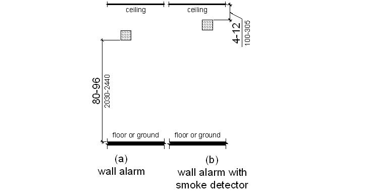
**702.3.3.1 Wall Installed Appliances. **Appliances shall be located 80 inches (2030 mm) minimum and 96 inches (2440 mm) maximum above the finished deck surface measured to the bottom of the appliance.
Advisory - Chapter 9 of this report, in section 307.4, contains an exception where the main deck is less than 3,000 square feet, the minimum vertical clearance is permitted to be reduced to 78 inches (1980 mm). In such situations, the appliances shall be located 78 inches (1980 mm) above the finished deck surface.
**EXCEPTION: **Wall installed appliances which are part of a smoke detector shall be located 4 inches (100 mm) minimum and 12 inches (305 mm) maximum below the ceiling measured to the top of the smoke detector.
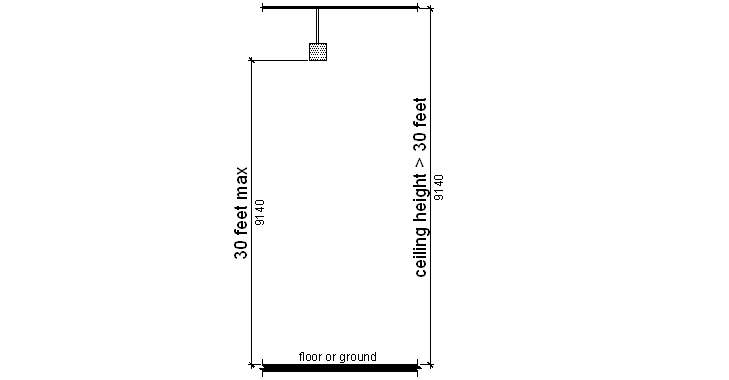
**702.3.3.2 Ceiling-Installed Appliances. **Appliances shall be on the ceiling. Where ceiling height exceeds 30 feet (9140 mm), appliances shall be suspended from the ceiling to a height of 30 feet (9140 mm) maximum above the finished deck surface.
**702.3.4 Spacing Allocation and Minimum Intensity. **Spacing and minimum effective intensity for appliances shall comply with 702.3.4.
EXCEPTION 1. Appliances in corridors not more than 20 feet (6100 mm) in width shall comply with 702.3.5.
EXCEPTION 2. Appliances in passenger staterooms shall comply with 702.3.6.
**702.3.4.1 General. **The signal provided by the appliance or appliances shall be visible either by direct view or by reflection from all parts of the covered area. Multiple appliances within an area are permitted only where size, shape, passenger vessel construction or furnishings prohibit total coverage by a single appliance. Where multiple appliances are provided in a single area to provide total area coverage, the appliances shall comply with one of the following: a maximum of two appliances located on opposite walls; the appliances shall have synchronized flashes; or, in rooms 80 feet (24 m) by 80 feet (24 m) or greater in size, more than two appliances located such that all appliances in any 135-degree field of view are spaced a minimum of 55 feet (17 m) from each other.
**702.3.4.2 Wall Installed Appliances. **Spacing and minimum effective intensity for wall installed appliances shall be in accordance with Table 702.3.4.2 provided the appliance is located at the midpoint of the longest side of the area served. Where the appliance is not located at the midpoint, the minimum effective intensity shall be based on a maximum area of coverage equal to the distance to the opposite side of the area served or double the distance to the farthest adjacent side of the area served, whichever is greater.
Table 702.3.4.2 Spacing Allocation for Wall-Installed Visual Alarm Appliances
| Maximum Area of Coverage in Feet | Minimum Required Light Output (Effective Intensity)(candela) | ||
| 1 Light Per Area | 1 Lights Per Area | 4 Lights Per Area | |
| 20 X 20 (6100 X 6100 mm) | 15 | Not Permitted | Not Permitted |
| 30 X 30 (9140 X 9140 mm) | 30 | 15 | Not Permitted |
| 40 X 40(12 X 12 m) | 60 | 30 | Not Permitted |
| 50 X 50 (15 X 15 m) | 95 | 60 | Not Permitted |
| 60 X 60 (18 X 18 m) | 135 | 95 | Not Permitted |
| 70 X 70 (21 X 21 m) | 185 | 95 | Not Permitted |
| 80 X 80 (24 X 24 m) | 240 | 135 | 60 |
| 90 X 90 (27 X 27 m) | 305 | 185 | 95 |
| 100 X 100 (30 X 30 m) | 375 | 240 | 95 |
| 110 X 110 (34 X 34 m) | 455 | 240 | 135 |
| 120 X 120 (37 X 37 m) | 540 | 305 | 135 |
| 130 X 130 (40 X 40 m) | 635 | 375 | 185 |
702.3.4.3 Ceiling Installed Appliances. Spacing and minimum effective intensity for ceiling installed appliances shall be in accordance with Table 702.3.4.3 provided the appliance is located at the centerpoint of the area served. Where the appliance is not located at the centerpoint, the minimum effective intensity shall be based on a maximum area of coverage equal to two times the distance from the appliance to the farthest side of the area served.
Table 702.3.4.3 Spacing Allocation for Ceiling-Installed Visual Alarm Appliances
| Maximum Area of Coverage in Feet | Minimum Required Light Output (Effective Intensity) (candela) | |
| Maximum Ceiling Height in Feet | One Light | |
| 20 X 20 (6100 X 6100 mm) | 10 (3050 mm) | 15 |
| 30 X 30 (9140 X 9140 mm) | 10 (3050 mm) | 30 |
| 40 X 40 (12 X 12 m) | 10 (3050 mm) | 60 |
| 50 X 50 (15 X 15 m) | 10 (3050 mm) | 95 |
| 20 X 20 (6100 X 6100 mm) | 20 (6100 mm) | 30 |
| 30 X 30 (9140 X 9140 mm) | 20 (6100 mm) | 45 |
| 40 X 40 (12 X 12 m) | 20 (6100 mm) | 80 |
| 50 X 50 (15 X 15 m) | 20 (6100 mm) | 115 |
| 20 X 20 (6100 X 6100 mm) | 30 (9140 mm) | 55 |
| 30 X 30 (9140 X 9140 mm) | 30 (9140 mm) | 75 |
| 40 X 40 (12 X 12 m) | 30 (9140 mm) | 115 |
| 50 X 50 (15 X 15 m) | 30 (9140 mm) | 150 |
**702.3.5 Corridor Spacing Allocation and Minimum Intensity. **Appliances in corridors that are 20 feet (6100 mm) maximum in width shall comply with 702.3.5. Corridors exceeding 20 feet (6100 mm) in width shall comply with 702.3.4.
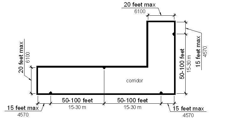
702.3.5.1 Appliance Spacing. Appliances shall be located 15 feet (4570 mm) maximum from each end of the corridor and shall be located 50 feet (15 m) minimum and 100 feet (30 m) maximum apart along the corridor. Interruptions to the concentrated viewing path by doors, elevation changes or other obstructions shall constitute the end of a corridor for purposes of this section.
702.3.5.2 Minimum Effective Intensity. Appliances shall have a minimum effective intensity of 15 candela.
**702.3.6 Alarms in Staterooms. **Passenger staterooms required to have visual alarms shall comply with 702.3.6.1 through 702.3.6.3.
**702.3.6.1 Activation. **Activation of such installed alarms shall be an integral part of a supervised alarm system in accordance with the regulations of the administrative authority having jurisdiction.
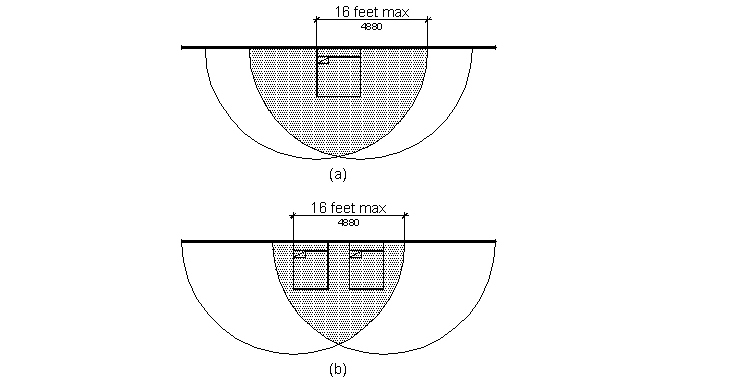
**702.3.6.2 Location. **In sleeping rooms or suites having a linear dimension exceeding 16 feet (4880 mm), the appliance shall be located 16 feet (4880 mm) maximum from the head end of the bed location, measured horizontally. An appliance shall be provided in each sleeping room/stateroom. The alarm signal shall be visible from all parts of each sleeping room.
**702.3.6.3 Minimum Effective Intensity and Mounting Height. **Wall mounted appliances located 24 inches (610 mm) minimum below the ceiling shall have a minimum effective intensity of 110 candela. Ceiling mounted appliances and wall mounted appliances located less than 24 inches (610 mm) below the ceiling shall have a minimum effective intensity of 177 candela.