
Passenger Vessels Access Advisory Committee
Chapter 1 Onboard Accessible Routes
*Standards and sections from the ADAAG Review Report referenced in this report that have not been reviewed or approved by the committee.
Note: This chapter only applies to passenger vessels subject to subchapters K or H, except where sections are referenced by chapter 12 which addresses subchapters C and T vessels.
Note: Several recommendations incorporate engineering standards published by ASME, ANSI, BHMA and other engineering standards setting organizations. The committee did not review these standards, which were included by reference. Therefore, the committee recommends that the competent regulatory drafting authorities and others specifically review all referenced industry standards to determine their suitability in designing equipment for use onboard ships in the marine environment.
Note: The committee recognizes that these recommendations may apply to vessels not built or constructed in U.S. shipyards, and to systems not manufactured in the United States. Therefore, the committee recommends that the final regulations recognize and accept the use of other equivalent standards, such as the International Standards Organization standards and recommendations, International Electro-Technical Commission Engineering standards and recommendations, Japan Engineering Standards, etc.
Measurements: All measurements are determined based on the vessel’s static design condition.
SCOPING
206 Accessible Routes Onboard a Passenger Vessel
206.1 General. Accessible routes shall be provided onboard a passenger vessel in accordance with 206.
206.2 Where Required. Onboard accessible routes shall be provided where required by 206.2.1 through 206.2.8 and shall comply with 401.
206.2.1 Not Used.
206.2.2 Not Used.
206.2.3 Multi-Level Passenger Vessels. At least one accessible route shall connect each level required to be accessible, including mezzanines, onboard multi-deck passenger vessels.
Note: The following Exception 1, and notes 1 through 3, were provided by the Access Board.
EXCEPTION 1. An accessible route is not required to levels located above or below the accessible level in passenger vessels that are less than three decks or that have less than 3,000 square feet (280 m2) per deck.
Note 1: The DOT may revisit the application of the elevator exception to the vessels based on comments received in response to future rulemaking.
Note 2: The elevator exception does not apply to State and local governments. (See 28 CFR 35.151(c)).
Note 3: This is the minimum baseline. The DOJ, DOT, or the Access Board (or PVAAC) may expand the exception or develop additional exceptions.
EXCEPTION 2. An accessible route is not required between decks on a high speed ferry with only two passenger decks where all types of passenger facilities are available on the accessible deck.
Advisory 206.2.3 Exception 2: Types of passenger facilities that may be found on high speed ferries with two passenger decks. Seating area, Viewing area, Restrooms, Snack Bar, Open deck area, Gift shop, Dining area, and Baggage storeroom.
EXCEPTION 3. An accessible route is not required to a deck which is less than 300 (28 m2) square feet in size.
Note: The committee understands that where a deck is not required to be connected to an accessible route, the spaces on that deck which were required to be accessible by this report still must be accessible.
206.2.4 Accessible Spaces and Elements. At least one accessible route shall connect all accessible spaces and elements onboard the passenger vessel which are otherwise connected by a circulation path.
**EXCEPTION: **An accessible route is not required between levels where exempted by 206.2.3.
206.2.5 Dining Areas. An accessible route shall be provided to all dining areas, including raised or sunken dining areas, and outdoor seating areas.
EXCEPTION: In passenger vessels without elevators, an accessible route to a mezzanine dining area is not required, provided that the mezzanine contains less than 25 percent of the total area for seating and dining and the same services are provided in the accessible area.
**206.2.6 Performance Areas. **An accessible route shall be provided where a circulation path directly connects a performance area to an assembly seating area. An accessible route shall be provided from performance areas to ancillary areas or facilities used by the public.
**206.2.7 Raised Platforms. **In banquet rooms or spaces where a head table or speaker’s lectern is located on a raised platform, an accessible route shall be provided to the platform.
**206.2.8 Vessel Entry and Departure Points. **In all ports, an accessible route shall be provided to at least one vessel entry and departure point used by passengers.
**EXCEPTION: **An accessible route is not required between levels where exempted by 206.2.3.
Note: Access requirements for getting on and off a vessel are addressed in chapter 2 (On/Off Accessible Routes).
**206.3 Location. **Accessible routes shall coincide with or be located in the same area as a general circulation path. Where the circulation path is interior, the accessible route shall also be interior. An accessible route connecting any two points within one or more accessible spaces shall not be more than 300 feet (91 m) longer than the shortest general circulation path connecting the same two points.
206.3.1 Signage. Where an accessible route does not coincide with a general circulation path, directional signage to an accessible route shall be provided.
206.4 Not Used.
206.5 Doors and Doorways. Accessible doors and doorways shall be provided in accordance with 206.5.1 through 206.5.3 and shall comply with 404.
206.5.1 Accessible Entry and Departure Points. Each accessible entry and departure point shall have at least one accessible door or doorway.
206.5.2 Accessible Rooms and Spaces. Onboard a passenger vessel, at least one door or doorway serving each accessible room or space shall be accessible.
206.5.3 Weather Deck Access. Where the main deck of a passenger vessel is greater than 3,000 square feet (280 m2) at least one exterior door on each accessible weather deck shall comply with 404.2.5 and shall be located on an accessible route that provides access between the weather deck and the interior of the passenger vessel, except where prohibited by an administrative authority having jurisdiction.
206.6 Elevators. New passenger elevators shall comply with 407.2 or 407.3. Where multiple elevators are provided, each passenger elevator shall comply with 407.2 or 407.3.
EXCEPTION 1. Where an elevator is provided in a passenger vessel eligible for the exceptions to 206.2.3, the elevator shall comply with 407.2, 407.3 or 407.4.
EXCEPTION 2. Where each deck of a ferry is less than 3,000 square feet (280 m2), elevators are permitted to comply with 407.4.
EXCEPTION 3. Where a passenger vessel is less than 5,000 International Tonnage Convention (ITC), elevators are permitted to comply with 407.4.
EXCEPTION 4. Where a passenger vessel is less than 10,000 International Tonnage Convention (ITC) and multiple elevators are provided, only one elevator is required to comply with 407.2 or 407.3 and all other elevators are permitted to comply with 407.4.
206.7 Wheelchair (Platform) Lifts. Wheelchair (platform) lifts shall be permitted as a component of an accessible route in new construction as permitted by 206.7.1 through 206.7.4, and shall comply with 408.
206.7.1 Performance Areas. Wheelchair (platform) lifts shall be permitted to provide an accessible route to a performance area in an assembly occupancy.
206.7.2 Wheelchair Spaces. Wheelchair (platform) lifts shall be permitted to comply with the wheelchair space dispersion and line-of-sight requirements of 221* and 802*.
206.7.3 Incidental Spaces. Wheelchair (platform) lifts shall be permitted to provide an accessible route to incidental occupiable spaces and rooms which are not open to the general public and which are occupied by five persons maximum, including but not limited to equipment control rooms and projection booths.
206.7.4 Decks Less Than 3,000 Square Feet. Wheelchair (platform) lifts shall be permitted to provide an accessible route to a deck which is less than 3,000 square feet (280 m2) in size.
TECHNICAL
401 General
401.1 Scope. Accessible routes required by this report shall comply with the applicable provisions of this chapter.
402 Accessible Routes
402.1 General. Accessible routes shall comply with 402.
**402.2 Components. **Accessible routes shall consist of one or more of the following components:
a. Walking surfaces with a slope not steeper than 1:20;
b. doorways;
c. ramps, (note: includes curb ramps);
d. elevators; and
e. platform (wheelchair) lifts.
All components of an accessible route shall comply with the applicable portions of this chapter.
403 Walking Surfaces
403.1 General. Walking surfaces that are a part of an accessible route shall comply with 403.
403.2 Deck Surface. Finished deck surfaces shall comply with 302.
403.3 Slope. The running slope of walking surfaces shall not be steeper than 1:20. The cross slope of walking surfaces shall not be steeper than 1:20.
403.4 Changes in Level. Changes in level shall comply with 303.
**403.5 Clear Width. **The clear width of walking surfaces shall be 36 inches (915 mm) minimum.
EXCEPTION 1. The clear width shall be 32 inches (815 mm) minimum for a length of 24 inches (610 mm) maximum, provided that multiple 32 inch (815 mm) wide segments are separated by segments that are 48 inches (1220 mm) minimum in length and 36 inches (915 mm) minimum in width.
EXCEPTION 2. Where a main deck of a passenger vessel is less than 3,000 square feet (280 m2) in size, the walking surface shall be permitted to have a clear width of 32 inches (815 mm) minimum.
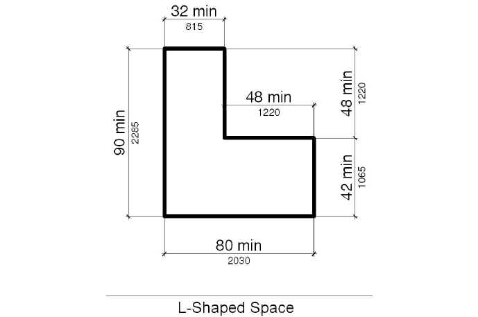
**403.5.1 Clear Width at Turn. **Where the accessible route makes a 180 degree turn around an object which is less than 48 inches (1220 mm) wide, clear width shall be 42 inches (1065 mm) minimum approaching the turn, 48 inches (1220 mm) minimum during the turn and 42 inches (1065 mm) minimum leaving the turn. Where the accessible route makes a 90 degree turn around an object, an L-shaped space with one stroke 90 inches (2285 mm) minimum in length having a width of 32 inches (815 mm) minimum and the other stroke with a 80 inches (2030 mm) minimum length having a width of 42 inches (1065 mm) minimum shall be provided.
403.5.2 Passing Spaces. An accessible route with a clear width less than 60 inches (1525 mm) shall provide passing spaces at intervals of 200 feet (61 m) maximum. Passing spaces shall be either a 60 inches (1525 mm) minimum by 60 inches (1525 mm) minimum space, or an intersection of two walking surfaces which provide a T-shaped space complying with 304.
403.5.3 Protruding Objects. Protruding objects shall comply with 307. Protruding objects shall not reduce the required clear width.
404 Doors and Doorways
**404.1 General. **Doors and doorways that are part of an accessible route shall comply with 404.
**404.2 Manual Doors and Doorways. **Manual doors and doorways and manual gates, including ticket gates, shall comply with 404.2.1 through 404.2.11.
**404.2.1 Revolving Doors and Turnstiles. **Revolving doors and revolving turnstiles shall not be part of an accessible route.
**404.2.2 Double-Leaf Doors. **At least one of the active leaves of doorways with two independently operated leaves shall comply with 404.2.3 and 404.2.4.
**404.2.3 Clear Width. **Doorways shall have a clear opening of 32 inches (815 mm) minimum. Clear openings of doorways with swinging doors shall be measured between the face of the door and the stop, with the door open 90 degrees. Openings more than 24 inches (610 mm) in depth shall provide a clear opening of 36 inches (915 mm) minimum. There shall be no projections into the required clear opening width lower than 34 inches (865 mm) above the finished deck surface. Projections into the clear opening width between 34 inches (865 mm) and 80 inches (2030 mm) above the finished deck surface shall not exceed 4 inches (100 mm).
Advisory - The present ADAAG allows equipment to be on an accessible door that creates a “key-hole” situation where the lower portion of the door opening is 32 inches (815 mm) clear, but the upper portion of the accessible door reduces the clear path of travel to 25 inches (635 mm) (reduce the path of travel on each side of the doorway up to 4 inches). If the ADAAG criteria for accessible doors was meant to allow for projecting door hardware, it should be clearly stated.
404.2.4 Maneuvering Clearances.
**404.2.4.1 Swinging Doors. **Approaches to swinging doors shall have maneuvering clearances complying with Table 404.2.4.1.
Table 404.2.4.1 Maneuvering Clearances at Manual Swinging Doors.
| TYPE OF USE | MINIMUM MANEUVERING CLEARANCE 1 | ||
| Approach Direction | Door Side | Perpendicular to Doorway | Parallel to Doorway 2\ |
| (beyond latch side unless noted) | |||
| From front | Pull | 60 inches (1525 mm) | 18 inches (455 mm), 24 inches (610 mm) preferred |
| From front | Push | 48 inches (1220 mm) | 0 inches (0 mm) 3 |
| From hinge side | Pull | 60 inches (1525 mm) | 36 inches (915 mm) |
| From hinge side | Pull | 54 inches (1370 mm) | 42 inches (1065 mm) |
| From hinge side | Push | 48 inches (1220 mm) 4 | 22 inches (560 mm) beyond hinge side |
| From latch side | Pull | 48 inches (1220 mm) 5 | 24 inches (610 mm) |
| From latch side | Push | 42 inches (1065 mm) 5 | 24 inches (610 mm) |
Notes:
1. Maneuvering clearance shall include the full width of the doorway.
2. Doors to hospital patient sleeping rooms are exempt from the clearance beyond the latch side of the door provided the door is 44 inches (1120 mm) wide minimum.
3. Add 12 inches (305 mm) if closer and latch are provided.
4. Add 6 inches (150 mm) if closer and latch are provided.
5. Add 6 inches (150 mm) if closer and latch are provided.Figure 404.2.4.1
404.2.4.2 Doorways without Doors, Sliding Doors and Folding Doors. Approaches to doorways without doors which are less than 36 inches (915 mm) wide and approaches to sliding and folding doors shall have maneuvering clearances complying with Table 404.2.4.2.

Table 404.2.4.2 Maneuvering Clearances at Doorways without Doors, Manual Sliding Doors, and Manual Folding Doors.
| MINIMUM MANEUVERING CLEARANCE 1 | ||
| Approach Direction | Perpendicular to Doorway | Parallel to Doorway 2 (beyond stop/latch side unless noted) |
| From Front | 48 inches (1220 mm) | 0 inches ( 0 mm) |
| From side (doorway with no door only) | 42 inches (1065 mm) | 0 inches (0 mm) |
| From pocket/hinge side | 42 inches (1065 mm) | 22 inches (560 mm) beyond pocket/hinge side |
| From stop/latch side | 42 inches(1065 mm) | 24 inches (610 mm) |
Notes:
1. Maneuvering clearance shall include the full width of the doorway.
2. Doors to hospital patient sleeping rooms are exempt from the clearance beyond the stop/latch side of the door provided the door is 44 inches (1120 mm) wide minimum.
**404.2.4.3 Doors in Alcoves. **Doors in alcoves where the plane of the doorway is offset more than 8 inches (205 mm) from the plane of the wall shall provide maneuvering clearances for front approach.
**404.2.4.4 Deck Surface. **Finished deck surface within required maneuvering clearances shall have a slope of 1:48 maximum and shall comply with 302. Changes in level are not permitted.
**404.2.5 Thresholds. **Thresholds, if provided at doorways, shall be 1/2 inch (13 mm) maximum in height. Raised thresholds and changes in level at doorways shall comply with 302 and 303.
**404.2.6 Two Doors in Series. **The distance between two hinged or pivoted doors in series shall be 48 inches (1220 mm) minimum plus the width of any door swinging into the space. Doors in series shall swing either in the same direction or away from the space between the doors.
**404.2.7 Door Hardware. **Handles, pulls, latches, locks, and other operable parts on accessible doors shall comply with 309.4. Such hardware shall be 30 inches (760 mm) minimum and 44 inches (1120 mm) maximum above the finished deck surface. When sliding doors operated by passengers are in the fully open position, operating hardware shall be exposed and usable from both sides.
**EXCEPTION: **Locks used only for security purposes and not used for normal operation are permitted in any location.
404.2.8 Closing Speed.
**404.2.8.1 Door Closers. **Door closers shall be adjusted so that from an open position of 90 degrees, the time required to move the door to an open position of 12 degrees is 5 seconds minimum.
404.2.8.2 Spring Hinges. Door spring hinges shall be adjusted so that from the open position of 70 degrees, the door shall move to the closed position in 1.5 seconds minimum, measured under ambient conditions.
**404.2.9 Door Opening Force. **Fire doors and water tight doors shall have a minimum opening force allowable by the appropriate administrative authority. The required force for pushing or pulling open a door other than fire doors and water tight doors shall be as follows:
1. Interior hinged doors: 5 lbs (22.2 N) maximum under normal operating conditions.
2. Sliding or folding doors: 5 lbs (22.2 N) maximum under normal operating conditions.
These forces do not apply to the force required to retract latch bolts or disengage other devices that hold the door in a closed position.
**EXCEPTION: **Section 404.2.9 does not apply to sailing vessels.
**404.2.10 Door Surface. **The bottom 10 inches (255 mm) of all swinging doors shall have a smooth surface on the push side and extending the full width of the door. Parts creating horizontal or vertical joints in such surface shall be within 1/16 inch (1.6 mm) of the same plane as the other. Cavities created by added kick plates shall be capped.
EXCEPTION 1. This requirement shall not apply to sliding doors.
EXCEPTION 2. Tempered glass doors without stiles and having a bottom rail or shoe with the top leading edge tapered at 60 degrees minimum from the horizontal shall not be required to meet the 10 inch (255 mm) bottom rail height requirement.
EXCEPTION 3. This requirement shall not apply to doors that do not extend to within 10 inches (255 mm) of the finished deck surface.
**404.2.11 Vision Lites. **Doors, and sidelites adjacent to doors, containing one or more glazing panels that permit viewing through the panels shall have the bottom of at least one glazed panel located 43 inches (1090 mm) maximum above the finished deck surface.
404.3 Automatic Doors. Automatic doors and automatic gates shall comply with 404.3.1 through 404.3.6. Full-powered automatic doors shall comply with ANSI/BHMA A156.10. Low-energy and power-assisted doors shall comply with ANSI/BHMA A156.19.
404.3.1 Clear Width. Doorways shall have a clear opening of 32 inches (815 mm) minimum in power-on and power-failure mode. The minimum clear width for automatic door systems shall be based on the clear opening provided by all leafs in the open position.
404.3.2 Maneuvering Clearance. Clearances at power-assisted doors shall comply with 404.2.4.
**404.3.3 Thresholds. **Thresholds and changes in level at doorways shall comply with 404.2.5.
**404.3.4 Two Doors in Series. **Doors in series shall comply with 404.2.6.
**404.3.5 Controls and Operating Mechanisms. **Control switches shall comply with 309.
*404.3.6 Signs. **Labels and warnings for automatic doors shall comply with 703.4.
404.4 Doors with Coamings. Doors such as weathertight and watertight doors, that have coamings which exceed ½ inch (13 mm) in height shall comply with 404.2 (manual accessible doors) or 404.3 (automatic and power assisted accessible doors) unless modified by 404.4, and shall comply with the applicable sections of 405 (ramps), unless modified by 404.4.
Note: Coaming Definition. The vertical plating bounding a hatch or located at the base of a door for the purpose of stiffening the edges of the opening and resisting entry of water. Coamings may be required by U.S. Coast Guard regulations or provided as part of good design practice.
404.4.1 Double Ramp Access.
a. Automatic. The doors shall be automatic.
b. Thresholds. Thresholds on each side of the doors shall have the minimum height allowed by the Coast Guard or established by the design professional.
**c. **Not Used.
d. Slope. Running slopes on both sides of the doors shall not exceed 1:12.
e. Handrails. Where handrails are required by 405.8, handrail extensions are not required at the top of the ramps.
f. Landings. Where 405 applies, landings are not required at the top of the two ramps.
404.4.2 Single Ramp Access.
a. Ramp Side Threshold. The ramp side of the doors shall have the minimum threshold height allowed by Coast Guard coaming regulations or established by the design professional.
b. Ramp Side Maneuvering Clearance. The maneuvering clearance on the ramp side of the doors shall have a running slope complying with 403 (walking surfaces) or 405 (ramps).
**EXCEPTION: **Where the door is automatic, the maneuvering clearance is not required.
c. Landing Side Thresholds and Maneuvering Clearances. Thresholds on the landing side of the doors shall comply with 404.2.5, and shall have a maneuvering clearance 48 inches (1220 mm) minimum in length perpendicular to the doorway.
**EXCEPTION: **Where the door is automatic, the maneuvering clearance is not required.
d. Handrail Extensions. Where handrails are required by 405.8, handrail extensions are not required at the top of the ramp.
405 Ramps
**405.1 General. **Walking surfaces on accessible routes with a running slope steeper than 1:20 are ramps and shall comply with 405.
**405.2 Slope. **Ramp runs shall have a running slope not steeper than:
a. 1:4 if the rise is 3 inches (75 mm) maximum;
b. 1:6 if the rise is 6 inches (150 mm) maximum;
c. 1:8 if the rise is 9 inches (230 mm) maximum; or
d. 1:12 if the rise is greater than 9 inches (230 mm).
**405.3 Cross Slope. **Cross slope of ramp runs shall not be steeper than 1:48.
**405.4 Deck Surfaces. **Finished deck surfaces of ramp runs shall comply with 302. Changes in level other than the running slope and cross slope are not permitted on ramp runs.
405.5 Clear Width. The clear width of a ramp run and the clear width between handrails, if provided, shall be 36 inches (915 mm) minimum.
**EXCEPTION: **Where a main deck of a passenger vessel is less than 3,000 square feet (280 m2) in size, the width of ramp runs and the distance between handrails, if provided, shall be permitted to have clear widths of 32 inches (815 mm) minimum.
**405.6 Rise. **The rise for any ramp run shall be 30 inches (760 mm) maximum.
**405.7 Landings. **Ramps shall have landings at the bottom and top of each ramp run. Landings shall comply with 405.7.1 through 405.7.5.
**405.7.1 Slope. **Landings shall have a slope not steeper than 1:48 and shall comply with 302. Changes in level are not permitted.
405.7.2 Width. The landing shall be at least as wide as the widest ramp run leading to the landing.
**405.7.3 Length. **The landing length shall be 48 inches (1220 mm) minimum.
**405.7.4 Change in Direction. **Ramps that change direction between runs at landings shall have a 60 inches (1525 mm) minimum by 60 inches (1525 mm) minimum landing.
405.7.5 Doorways. Where doorways are located adjacent to a ramp landing, maneuvering clearances required by 404.2.4 and 404.3.2 shall be permitted to overlap the required landing area.
405.8 Handrails. Ramp runs with a rise greater than 6 inches (150 mm) shall have handrails complying with 505*.
**405.9 Edge Protection. **Edge protection complying with 405.9.1 or 405.9.2 shall be provided on each side of ramp runs and at each side of ramp landings.
EXCEPTION 1. Edge protection is not required on ramps that are not required to have handrails and have sides complying with 406.3.
EXCEPTION 2. Edge protection is not required on the sides of ramp landings serving an adjoining ramp run or stairway.
EXCEPTION 3. Edge protection is not required on the sides of ramp landings having a vertical drop-off of ½ inch (13 mm) maximum within 10 inches (255 mm) horizontally of the minimum landing area.
*405.9.1 Extended Deck Surface. **The finished deck surface of the ramp run or landing shall extend 12 inches (305 mm) minimum beyond the inside face of a handrail complying with 505.
**405.9.2 Guard, Curb or Barrier. **A guard, curb, or barrier shall be provided that prevents the passage of a 4 inches (100 mm) diameter sphere, where any portion of the sphere is within 4 inches (100 mm) of the finished deck surface.
**405.10 Outdoor Conditions. **Outdoor ramps and outdoor approaches to ramps shall be designed so that water will not accumulate on walking surfaces.
406 Curb Ramps
**406.1 General. **Curb ramps on accessible routes shall comply with 406 and with 405.2, 405.4, 405.5 and 405.10.
**406.2 Counter Slope. **Counter slopes of adjoining gutters and road surfaces immediately adjacent to the curb ramp shall not be steeper than 1:20. The adjacent surfaces at transitions at curb ramps to walks, gutters and streets shall be at the same level.
**406.3 Sides of Curb Ramps. **Curb ramps located where pedestrians must walk across the ramp shall have flared sides. Slope of the flares shall not be steeper than 1:10. Where the width of the walking surface at the top of the ramp and parallel to the run of the ramp is less than 48 inches (1220 mm) wide, the flared sides shall have a slope not steeper than 1:12. Curb ramps with returned curbs shall be permitted where pedestrians would not normally walk across the ramp.
**406.4 Handrails. **Handrails are not required on curb ramps.
**406.5 **Not Used.
**406.6 **Not Used.
406.7 Not Used.
407 Elevators
**407.1 General. **New elevators required to be accessible shall comply with 407.2. New destination-oriented elevators required to be accessible shall comply with 407.3. New limited use/limited application elevators required to be accessible shall comply with 407.4. Altered elements of existing elevators shall comply with 407.5.
*407.2 New Elevators. **New accessible elevators shall comply with 407.2.1 through 407.2.13 and with ASME/ANSI A17.1. They shall be passenger elevators as classified by ASME/ANSI A17.1*.
**407.2.1 Automatic Operation. **Elevator operation shall be automatic. Each car shall be equipped with a self-leveling feature that will automatically bring and maintain the car at finished deck surface landings within a tolerance of 1/2 inch (13 mm) under rated loading to zero loading conditions.
407.2.2 Call Buttons. Call buttons in elevator lobbies and halls shall be located vertically between 35 inches (890 mm) and 48 inches (1220 mm) above the finished deck surface, measured to the centerline of the button. A clear deck space complying with 305 shall be provided. Such call buttons shall have visible signals consisting of a white light to indicate when each call is registered and when each call is answered. Call buttons shall be 3/4 inch (19 mm) minimum in the smallest dimension. The button that designates the up direction shall be located above the button that designates the down direction. Buttons shall be raised or flush. If the button is flush, a tactile distinction shall be placed on the button to differentiate it from the surrounding surface. No protruding objects shall be located within the space beneath the hall call button measuring 6 inches (150 mm) minimum to the right and left of the button center.
**407.2.3 Hall Signals. **A visible and audible signal shall be provided at each hoistway entrance to indicate which car is answering a call and the direction of travel. Alternatively, in-car signals shall be located in cars, visible from the deck area adjacent to the hall call buttons, and shall comply with the requirements of this section.
407.2.3.1 Audible Signals. Audible signals shall sound once for the up direction and twice for the down direction, or shall have verbal annunciators that state which direction the car is traveling. Audible signals or verbal annunciators shall have a frequency of 1500 Hz maximum. The audible signal or verbal annunciator shall be 20 dBA minimum and 80 dBA maximum, measured at the annunciator.
**407.2.3.2 Visible Signals. **Visible signals shall comply with 407.2.3.2.1 through 407.2.3.2.3.
**407.2.3.2.1 Height. **Hall signal fixtures shall be centered at 72 inches (1830 mm) minimum above the finished deck surface.
**407.2.3.2.2 Size. **The visible signal elements shall be 2-1/2 inches (64 mm) minimum in the smallest dimension.
407.2.3.2.3 Visibility. Signals shall be visible from the deck area adjacent to the hall call button.
*407.2.4 Tactile Signs on Hoistway Entrances. **Tactile character and Braille deck designations shall be provided on both jambs of elevator hoistway entrances and shall be 60 inches (1525 mm) above the finished deck surface, measured from the baseline of the characters. Where vessel entry points are provided on only one deck of the vessel, a tactile star shall also be provided on both jambs at the entry deck. Such characters shall be 2 inches (51 mm) high and shall comply with 703.2.
Advisory - Any panel containing Braille and/or tactile characters meant to be touched with the hand should be no more than 48 inches (1220 mm) above the finished deck surface measure from the center of the panel. This will ensure that the panel is accessible to people with visual and mobility impairments.
407.2.5 Doors. Elevator doors shall be the horizontal type. Elevator hoistway and car doors shall open and close automatically. Elevator doors shall be provided with a reopening device that shall stop and reopen a car door and hoistway door automatically if the door becomes obstructed by an object or person. The device shall be activated by sensing an obstruction passing through the opening at 5 inches (125 mm) and 29 inches (735 mm) above the finished deck surface. The device shall not require physical contact to be activated, although contact may occur before the door reverses. Door reopening devices shall remain effective for 20 seconds minimum.
407.2.6 Door and Signal Timing for Hall Calls. The minimum acceptable time from notification that a car is answering a call or designation of which car is assigned to a lobby destination deck entry until the doors of that car start to close shall be calculated from the following equation:
T = D/(1.5 ft/s) or
T = D/(455 mm/s) = 5 seconds minimum
where T equals the total time in seconds and D equals the distance (in feet or millimeters) from the point in the lobby or corridor 60 inches (1525 mm) directly in front of the farthest call button controlling that car to the centerline of its hoistway door. For cars with in-car lanterns, T begins when the signal is visible from the point 60 inches (1525 mm) directly in front of the farthest hall call button and the audible signal is sounded.
**407.2.7 Door Delay for Car Calls. **Elevator doors shall remain fully open in response to a car call for 3 seconds minimum.
**407.2.8 Inside Dimensions of Elevator Cars. **Clear width of elevator doors and inside dimensions of elevator cars shall comply with Table 407.2.8.
Table 407.2.8 Elevator Door and Car Sizes
| Minimum Dimensions | ||||
| Door Location | Door Clear Width | Inside Car, Side to Side | Inside Car, Back Wall to Front Return | Inside Car, Back Wall to Inside Face of Door |
| Centered | 36 inches (915 mm)1 | 54 inches (1370 mm) | 65 inches (1650 mm) | 68 inches (1725 mm) |
| Centered | 36 inches (915 mm)1 | 65 inches (1650 mm) | 54 inches (1370 mm) | 57 inches (1450 mm) |
| Centered | 42 inches (1065 mm) | 80 inches (2030 mm) | 51 inches (1295 mm) | 54 inches (1370 mm) |
| Side (off-centered) | 36 inches (915 mm)11 | 68 inches (1725 mm) | 51 inches (1295 mm) | 54 inches (1370 mm) |
| Any | 36 inches (915 mm)1 | 54 inches (1370 mm) | 80 inches (2030 mm) | 80 inches (2030 mm) |
| Any | 36 inches (915 mm)1 | 60 inches (1525 mm)12 | 60 inches (1525 mm)2 | 60 inches (1525 mm)2 |
Notes:
1. A tolerance of minus 5/8 inch (16 mm) is permitted.
2. Other car configurations that provide a wheelchair turning space complying with 304 with the door closed are permitted.
**407.2.9 Deck Surfaces. **Finished deck surfaces in elevator cars shall comply with 302. The clearance between the car platform sill and the edge of any hoistway landing shall be 1-1/4 inches (32 mm) maximum.
407.2.10 Illumination Levels. The level of illumination at the car controls, platform, car threshold and car landing sill shall be 5 footcandles (54 lux) minimum.
**407.2.11 Car Controls. **Elevator controls shall comply with 407.2.11.1 through 407.2.11.4.
**407.2.11.1 Buttons. **Buttons shall be 3/4 inch (19 mm) minimum in their smallest dimension. Buttons shall be raised or flush. If the button is flush, a tactile distinction shall be placed on the button to differentiate it from the surrounding surface. Buttons shall be arranged with numbers in ascending order. When two or more columns of buttons are provided they shall read from left to right. Keypads, where provided, shall be in a standard telephone keypad arrangement.
*407.2.11.2 Designations and Indicators for Control Buttons. **Control buttons shall be identified by tactile characters complying with 703.2. Characters and Braille shall be placed immediately to the left of the button to which the designations apply. The control button for the main entry deck and control buttons, other than remaining buttons with deck designations, shall be identified with tactile symbols as shown in Table 407.2.11.2. Buttons with deck designations shall be provided with visible indicators consisting of a white light to show that a call has been registered. The visible indication shall extinguish when the car arrives at the designated deck. Where provided, telephone-style keypad buttons shall be identified by tactile characters complying with 703.2* except that Braille is not required. Characters shall be centered on the corresponding keypad button.
**EXCEPTION: **Where a vessel entry point is provided on more than one deck of the vessel, the star symbol as shown in table 407.2.11.2 is not required.
Table 407.2.11.2 Elevator Control Button Identification
| Control Button | Tactile Symbol | Braille Message |
| Emergency Stop | insert symbol | insert symbol\ |
| “ST”OP Three cells | ||
| Alarm | insert symbol | insert symbol\ |
| AL”AR”M Four cells | ||
| Door Open | insert symbol | insert symbol\ |
| OP”EN” Three cells | ||
| Door Close | insert symbol | insert symbol\ |
| CLOSE Five cells | ||
| Entry Deck | insert symbol | insert symbol\ |
| MA”IN” Three cells | ||
| Phone | insert symbol | insert symbol\ |
| PH”ONE” Four cells |
\
**407.2.11.3 Height. **Buttons with deck designations shall be located 48 inches (1220 mm) maximum above the finished deck surface. Emergency controls, including the emergency alarm, shall be grouped at the bottom of the panel. Emergency control buttons shall have their centerlines 35 inches (890 mm) minimum above the finished deck surface.
**EXCEPTION: **Where the elevator serves more than 16 openings and parallel approach is provided, buttons with deck designations shall be located 54 inches (1370 mm) maximum above the finished deck surface.
**407.2.11.4 Location. **Controls shall be located to accommodate a forward reach or side reach as specified in 308.
**407.2.12 Car Position Indicators. **In elevator cars, audible and visible car location indicators shall be provided.
**407.2.12.1 Visible Indicators. **Indicators shall be located above the car control panel or above the door. Numerals shall be ½ inch (13 mm) high minimum. As the car passes a deck and when a car stops at a deck served by the elevator, the corresponding character shall illuminate.
**407.2.12.2 Audible Indicators. **The audible signal shall be 20 dBA minimum and 80 dBA maximum, measured at the annunciator, and shall have a frequency of 1500 Hz maximum. The signal shall be an automatic verbal announcement which announces the deck at which the car has stopped except an audible signal which sounds as the car passes or stops at a deck served by the elevator shall be acceptable for elevators with a rated speed of 200 feet per minute (1.02 m/s) or less.
*407.2.13 Emergency Communications. **Emergency two-way communication systems between the elevator car and a point outside the hoistway shall comply with ASME/ANSI A17.1. The highest operable part of a two-way communication system shall be 48 inches (1220 mm) maximum above the finished deck surface. The device shall be identified by tactile characters complying with 703.2 located adjacent to the device. If the system uses a handset, the handset shall be hearing-aid compatible and the cord from the panel to the handset shall be at least 29 inches (735 mm) minimum. The car emergency signaling device shall not be limited to voice communication. If instructions for use are provided, essential information shall be presented in both tactile (i.e., raised characters and Braille) and visual form.
*407.3 New Destination-Oriented Elevators. **New accessible destination-oriented elevators shall comply with 407.2.1, 407.2.4 through 407.2.10, and 407.2.13. Such elevators shall also comply with 407.3.1 through 407.3.5 and ASME/ANSI A17.1. They shall be passenger elevators as classified by ASME/ANSI A17.1*.
**407.3.1 Call Buttons. **Call buttons shall be located vertically between 35 inches (890 mm) and 48 inches (1220 mm) above the finished deck surface, measured to the centerline of the button. A clear deck space complying with 305 shall be provided. Call buttons shall be 3/4 inch (19 mm) minimum in the smallest dimension. Buttons shall be raised or flush. If the button is flush, a tactile distinction shall be placed on the button to differentiate it from the surrounding surface. No protruding objects shall be located within the space beneath the hall call button measuring 6 inches (150 mm) minimum to the right and left of the button center. A keypad or other means for the entry of destination information shall be provided. Keypads, where provided, shall be in a standard telephone keypad arrangement. Visible, consisting of a white light, and audible signals which indicate which elevator car to enter shall be provided.
**407.3.2 Hall Signals. **A visible and audible signal shall be provided to indicate a car destination corresponding with 407.3.1. The audible tone and verbal announcement shall be the same as those given at the call button or call button keypad. Each elevator in a bank shall have audible and visible means for differentiation.
**407.3.2.1 Visible Signals. **Visible signals shall comply with 407.3.2.1.1 through 407.3.2.1.3.
**407.3.2.1.1 Height. **Hall signal fixtures shall be centered at 72 inches (1830 mm) minimum above the finished deck surface.
**407.3.2.1.2 Size. **The visible signal elements shall be 2-1/2 inches (64 mm) minimum in the smallest dimension.
407.3.2.1.3 Visibility. Signals shall be visible from the deck area adjacent to the hoistway entrance.
**407.3.3 Car Controls. **Emergency controls, including the emergency alarm, shall have their centerlines 35 inches (890 mm) minimum and 48 inches (1220 mm) maximum above the finished deck surface. Buttons shall be 3/4 inch (19 mm) minimum in their smallest dimension. Buttons shall be raised or flush. If the button is flush, a tactile distinction shall be placed on the button to differentiate it from the surrounding surface. Controls shall be located to accommodate a forward reach or side reach as specified in 308.
**407.3.4 Car Position Indicators. **In elevator cars, audible and visible car location indicators shall be provided.
**407.3.4.1 Visible Indicators. **Indicators shall be located above the car control panel or above the door. Numerals shall be ½ inch (13 mm) high minimum. A display shall be provided in the car with visible indicators to show car destinations. The visible indicators shall extinguish when the call has been answered.
407.3.4.2 Audible Indicators. An automatic verbal announcement which announces the deck at which the car has stopped shall be provided. The announcement shall be 20 dBA minimum and 80 dBA maximum, measured at the annunciator.
*407.3.5 Elevator Car Identification. **In addition to the tactile signs required by 407.2.4, a tactile (i.e., raising characters and Braille) elevator car identification shall be placed immediately below the hoistway entrance deck designation. The characters shall be 2 inches (51 mm) high and shall comply with 703.2.
*407.4 New Limited-Use/Limited-Application Elevators. **New accessible limited-use/limited application elevators shall comply with 407.4.1 through 407.4.10 and shall comply with ASME/ANSI A17.1, Part XXV.
407.4.1 Automatic Operations. Elevator operation shall be automatic. Each car shall automatically stop at a finished deck surface landing within a tolerance of ½ inch (13 mm) under rated loading to zero loading conditions.
**407.4.2 Call Buttons. **Call buttons in elevator lobbies and halls shall be located vertically between 35 inches (890 mm) and 48 inches (1220 mm) above the finished deck surface, measured to the centerline of the button. Such call buttons shall have visible signals, consisting of a white light, to indicate when each call is registered and when each call is answered. Call buttons shall be 3/4 inch (19 mm) minimum in the smallest dimension, and shall be raised or flush. The button that designates the up direction shall be located above the button that designates the down direction. If the button is flush, a tactile distinction shall be placed on the button to differentiate it from the surrounding surface. No protruding objects shall be located within the space beneath the hall call button measuring 6 inches (150 mm) minimum to the right and left of the button center.
407.4.3 Hall Signals. A visible and audible signal complying with 407.2.3 shall be provided in the car or at each hoistway entrance to indicate the direction of travel.
*407.4.4 Tactile Signs on Hoistway Entrances. **Tactile character and Braille deck designations shall be provided on both jambs of elevator hoistway entrances and shall be 60 inches (1525 mm) above the finished deck surface measured from the baseline of the characters. Such characters shall be 2 inches (51 mm) high and shall comply with 703.2.
*407.4.5 Doors. **Elevator hoistway doors shall be either swinging or horizontally sliding type. Elevator hoistway and car doors shall open and close automatically. Horizontally sliding type hoistway and car doors shall comply with 407.2.5. Swinging hoistway doors shall conform to 404. Swinging doors shall be low energy power-operated and shall comply with ANSI/BHMA A156.19. Power operated swing doors shall remain open for 20 seconds minimum when activated.
**407.4.6 Inside Dimensions of Elevator Cars. **Elevator cars shall provide a clear width of 42 inches (1065 mm) minimum and a clear depth of 54 inches (1370 mm) minimum. Car doors shall be positioned at the narrow end of the car and shall provide a clear width of 32 inches (815 mm) minimum.
EXCEPTION 1. Ferries less than 1000 ITC are permitted to have elevators with a width of 36 inches (915 mm) minimum.
EXCEPTION 2. Passenger vessels less than 1000 ITC are permitted to have elevators with a width of 36 inches (915 mm) minimum provided they have straight through travel.
**407.4.7 Deck Surfaces. **Finished deck surfaces in elevator cars shall comply with 302. The horizontal distance between the car platform sill and the edge of any hoistway landing shall be 1-1/4 inches (32 mm) maximum.
**407.4.8 Illumination Levels. **The level of illumination at the car controls, platform, and car threshold and landing sill shall be 5 footcandles (53.8 lux) minimum.
**407.4.9 Car Controls. **Elevator controls shall comply with 407.2.11.1 through 407.2.11.3. Controls shall be centered on both side walls and shall comply with 309.
**407.4.10 Emergency Communications. **Car emergency signaling devices complying with 407.2.13 shall be provided.
408 Wheelchair (Platform) Lifts
408.1 General. Wheelchair (platform) lifts shall comply with ASME/ANSI A17.1* and with 302, 305 and 309. Wheelchair (platform) lifts shall not be attendant-operated and shall provide unassisted entry and exit from the lift.
*408.2 Doors and Gates. **Where a lift does not allow a user to pass through the lift, the lift shall have power-operated doors or gates. Where automatic doors or gates are provided, they shall be low energy power-operated and shall comply with ANSI/BHMA A156.19. Power operated doors and gates shall remain open for 20 seconds minimum when activated.