
Introduction
This document presents uniform standards for the design, construction and alteration of buildings so that physically handicapped persons will have ready access to and use of them in accordance with the Architectural Barriers Act, 42 U.S.C. 4151-4157. The document embodies an agreement to minimize the differences between the standards previously used by four agencies (the General Services Administration, the departments of Housing and Urban Development and Defense, and the United States Postal Service) that are authorized to issue standards under the Architectural Barriers Act, and between those standards and the access standards recommended for facilities that are not federally funded or constructed.
The four standard-setting agencies establish and enforce standards for design, construction, and alteration of particular types of buildings and facilities. The General Services Administration (GSA) prescribes standards for all buildings subject to the Architectural Barriers Act that are not covered by standards issued by the other three standard-setting agencies; the Department of Defense (DoD) prescribes standards for DoD installations; the Department of Housing and Urban Development (HUD) prescribes standards for residential structures covered by the Architectural Barriers Act except those funded or constructed by DoD; and the U.S. Postal Service (USPS) prescribes standards for postal facilities. Each of the four agencies issues standards in accordance with its statutory authority.
To ensure compliance with the standards, Congress established the Architectural and Transportation Barriers Compliance Board (ATBCB) in Section 502 of the Rehabilitation Act of 1973 (the Rehabilitation Act), 29 U.S.C. 792.
The ATBCB is composed of members representing eleven Federal agencies (the four standard-setting agencies; the departments of Education, Health and Human Services, Interior, Justice, Labor, and Transportation; and the Veterans Administration) and eleven members appointed by the President from the general public. A 1978 amendment to Section 502 of the Rehabilitation Act added to the ATBCB's functions the responsibility to issue minimum guidelines (Guidelines) and requirements for the standards established by the four standard-setting agencies. The final rule that established the Guidelines now in effect was published in the FEDERAL REGISTER on August 4, 1982 (47 FR 33862) and is codified at 36 CFR part 1190.
The four standard-setting agencies determined that the uniform standards adopted by them would, as much as possible, not only comply with the Guidelines adopted by the ATBCB but also be consistent with the standards published by the American National Standards Institute (ANSI) for general use. ANSI is a nongovernmental national organization that publishes a wide variety of recommended standards. ANSI's standards for barrier-free design are developed by a committee made up of 52 organizations representing associations of handicapped people, rehabilitation professionals, design professionals, builders, and manufacturers. The standards, which are called ANSI Al17.1, "Specifications for Making Buildings and Facilities Accessible to, and Usable by, Physically Handicapped People," are developed using the consensus process.
The original ANSI A117.1, adopted in 1961, formed the technical basis for the first accessibility standards adopted by the federal government and most state governments. The current edition, ANSI A117.1-1980, is based on research funded by HUD. It has generally been accepted by the private sector and has been recommended for use in model state and local building codes by the Council of American Building Officials.
In keeping with the objective of uniformity between federal requirements and those commonly applied by state and local governments, the Uniform Federal Accessibility Standards (UFAS) follows ANSI A117.1-1980 in format. Both the UFAS scope provisions, which establish the minimum number of elements and spaces required to comply with standards, and the UFAS technical requirements meet or exceed the comparable provisions of the Guidelines.
The UFAS was published in the FEDERAL REGISTER on August 7, 1984 (49 FR 31528). Each of the standard-setting agencies has taken action in accordance with its own procedures, including internally prescribed rulemaking and the Administrative Procedure Act where applicable, to incorporate the UFAS in its own standards, regulations, or other directives. GSA adopted the UFAS in 41 CFR 101-19.6, effective August 7, 1984. HUD adopted the UFAS in 24 CFR part 40, effective October 4, 1984. USPS adopted the UFAS in Handbook RE-4, "Standards for Facility Accessibility by the Physically Handicapped," effective November 15, 1984. DoD adopted the UFAS by revising Chapter 18 of DoD 4270.1-M, "Construction Criteria," by memorandum dated May 8, 1985.
[Note: Handbook RE-4, was amended effective April 16, 1986, by the addition of Interim Standards, Section 4.1.8, "Accessible Buildings: Leasing of Space in Existing Buildings." While Handbook RE-4, not UFAS, sets forth the governing standards for Postal facility accessibility. Handbook RE-4 may be further amended.]
1. Purpose
This document sets standards for facility accessibility by physically handicapped persons for Federal and federally-funded facilities. These standards are to be applied during the design, construction, and alteration of buildings and facilities to the extent required by the Architectural Barriers Act of 1968, as amended.
2. General
2.1 Authority
These standards were jointly developed by the General Services Administration, the Department of Housing and Urban Development, the Department of Defense, and the United States Postal Service, under the authority of sections 2, 3, 4, and 4a, respectively, of the Architectural Barriers Act of 1968, as amended, Pub. L. No. 90-480, 42 U.S.C. 4151-4157.
2.2 Provisions For Adults
The specifications in these standards are based upon adult dimensions and anthropometrics.
3. Miscellaneous Instructions And Definitions
3.1 Graphic Conventions
Graphic conventions are shown in Table 1. Dimensions that are not marked "minimum" or "maximum" are absolute, unless otherwise indicated in the text or captions.
3.2 Dimensional Tolerances
All dimensions are subject to conventional building industry tolerances for field conditions.
3.3 Notes
The text of these standards does not contain notes or footnotes. Additional information, explanations, and advisory materials are located in the Appendix. Paragraphs marked with an asterisk have related, nonmandatory material in the Appendix. In the Appendix, the corresponding paragraph numbers are preceded by an A.
3.4 General Terminology
- comply with
- Meet one or more specifications of this standard
- if, if...then
- a specification that applies only when the conditions described are present
- may
- an option or alternative
- shall
- a mandatory specification or requirement
- should
- an advisory specification or recommendation
3.5 Definitions
The following terms shall, for the purpose of these standards, have the meaning indicated in this section.
- access aisle
- An accessible pedestrian space between elements, such as parking spaces, seating, and desks, that provides clearances appropriate for use of the elements
- accessible
- A site, building, facility, or portion thereof that complies with these standards and that can be approached, entered, and used by physically disabled people
- accessible element
- An element specified by these standards (for example, telephone, controls, and the like)
- accessible route
- A continuous unobstructed path connecting all accessible elements and spaces in a building or facility. Interior accessible routes may include corridors, floors, ramps, elevators, lifts, and clear floor space at fixtures. Exterior accessible routes may include parking access aisles, curb ramps, walks, ramps, and lifts.
- accessible space
- Space that complies with these standards
- adaptability
- The ability of certain building spaces and elements, such as kitchen counters, sinks, and grab bars, to be added or altered so as to accommodate the needs of either disabled or nondisabled persons, or to accommodate the needs of persons with different types or degrees of disability
- addition
- An expansion, extension, or increase in the gross floor area of a building or facility
- administrative authority
- A governmental agency that adopts or enforces regulations and standards for the design, construction, or alteration of buildings and facilities
- alteration
- As applied to a building or structure, means a change or rearrangement in the structural parts or elements, or in the means of egress or in moving from one location or position to another. It does not include normal maintenance, repair, reroofing, interior decoration, or changes to mechanical and electrical systems.
- assembly area
- A room or space accommodating fifty or more individuals for religious, recreational, educational, political, social, or amusement purposes, or for the consumption of food and drink, including all connected rooms or spaces with a common means of egress and ingress. Such areas as conference rooms would have to be accessible in accordance with other parts of this standard but would not have to meet all of the criteria associated with assembly areas.
- automatic door
- A door equipped with a power-operated mechanism and controls that open and close the door automatically upon receipt of a momentary actuating signal. The switch that begins the automatic cycle may be a photoelectric device, floor mat, or manual switch mounted on or near the door itself (see power-assisted door).
- circulation path
- An exterior or interior way of passage from one place to another for pedestrians, including, but not limited to, walks, hallways, courtyards, stairways, and stair landings
- clear
- Unobstructed
- common use
- Refers to those interior and exterior rooms, spaces, or elements that are made available for the use of a restricted group of people (for example, residents of an apartment building, the occupants of an office building, or the guests of such residents or occupants)
- cross slope
- The slope that is perpendicular to the direction of travel (see running slope)
- curb ramp
- A short ramp cutting through a curb or built up to it
- dwelling unit
- A single unit of residence which provides a kitchen or food preparation area, in addition to rooms and spaces for living, bathing, sleeping, and the like. A single family home is a dwelling unit, and dwelling units are to be found in such housing types as townhouses and apartment buildings.
- egress, means of
- An accessible route of exit that meets all applicable code specifications of the regulatory building agency having jurisdiction over the building or facility
- element
- An architectural or mechanical component of a building, facility, space, or site, eg., telephone, curb ramp, door, drinking fountain, seating, water closet.
- entrance
- Any access point to a building or portion of building or facility used for the purpose of entering. An entrance includes the approach walk, the vertical access leading to the entrance platform, the entrance platform itself, vestibules if provided, the entry door(s) or gate(s), and the hardware of the entry door(s) or gate(s). The principal entrance of a building or facility is the main door through which most people enter.
- essential features
- Those elements and spaces that make a building or facility usable by, or serve the needs of, its occupants or users. Essential features include but are not limited to entrances, toilet rooms, and accessible routes. Essential features do not include those spaces that house the major activities for which the building or facility is intended, such as classrooms and offices.
- extraordinary repair
- The replacement or renewal of any element of an existing building or facility for purposes other than normal maintenance
- facility
- All or any portion of a building, structure, or area, including the site on which such building, structure or area is located, wherein specific services are provided or activities performed
- full and fair cash value
- Full and fair cash value is calculated for the estimated date on which work will commence on a project and means:
- The assessed valuation of a building or facility as recorded in the assessor's office of the municipality and as equalized at one hundred percent (100%) valuation, or
- The replacement cost, or
- The fair market value.
- functional spaces
- The rooms and spaces in a building or facility that house the major activities for which the building or facility is intended
- housing
- A building, facility, or portion thereof, excluding inpatient health care facilities, that contains one or more dwelling units or sleeping accommodations. Housing may include, but is not limited to, one and two-family dwellings, apartments, group homes, hotels, motels, dormitories, and mobile homes.
- marked crossing
- A crosswalk or other identified path intended for pedestrian use in crossing a vehicular way
- multifamily dwelling
- Any building containing more than two dwelling units
- operable part
- A part of a piece of equipment or appliance used to insert or withdraw objects, or to activate, deactivate, or adjust the equipment or appliance (for example, coin slot, pushbutton, handle)
- physically handicapped
- An individual who has a physical impairment, including impaired sensory, manual or speaking abilities, which results in a functional limitation in access to and use of a building or facility
- power-assisted door
- A door used for human passage with a mechanism that helps to open the door, or relieve the opening resistance of a door, upon the activation of a switch or a continued force applied to the door itself. If the switch or door is released, such doors immediately begin to close or close completely within 3 to 30 seconds (see automatic door).
- public use
- Describes interior or exterior rooms or spaces that are made available to the general public. Public use may be provided at a building or facility that is privately or publicly owned.
- ramp
- A walking surface in an accessible space that has a running slope greater than 1:20
- running slope
- The slope that is parallel to the direction of travel (see cross slope).
- service entrance
- An entrance intended primarily for delivery of services.
- signage
- Verbal, symbolic, tactile, and pictorial information
- site
- A parcel of land bounded by a property line or a designated portion of a public right-of-way
- site improvement
- Landscaping, paving for pedestrian and vehicular ways, outdoor lighting, recreational facilities, and the like, added to a site
- sleeping accommodations
- Rooms in which people sleep, for example, dormitory and hotel or motel guest rooms
- space
- A definable area, e.g., toilet room, hall, assembly area, entrance, storage room, alcove, courtyard, or lobby.
- structural impracticability
- Changes having little likelihood of being accomplished without removing or altering a load-bearing structural member and/or incurring an increased cost of 50 percent or more of the value of the element of the building or facility involved
- tactile
- Describes an object that can be perceived using the sense of touch
- tactile warning
- A standardized surface texture applied to or built into walking surfaces or other elements to warn visually impaired people of hazards in the path of travel
- temporary
- Applies to facilities that are not of permanent construction but are extensively used or essential for public use for a given (short) period of time, for example, temporary classrooms or classroom buildings at schools and colleges, or facilities around a major construction site to make passage accessible, usable, and safe for everybody. Structures directly associated with the actual processes of major construction, such as porto potties, scaffolding, bridging, trailers, and the like, are not included. Temporary as applied to elements means installed for less than 6 months and not required for safety reasons.
- vehicular way
- A route intended for vehicular traffic, such as a street, driveway, or parking lot
- walk
- An exterior pathway with a prepared surface intended for pedestrian use, including general pedestrian areas such as plazas and courts
4. Accessible Elements And Spaces: Scope And Technical Requirements
4.1 Minimum Requirements
4.1.1 Accessible Sites And Exterior Facilities: New Construction
An accessible site shall meet the following minimum requirements:
- (1) At least one accessible route complying with 4.3 shall be provided within the boundary of the site from public transportation stops, accessible parking spaces, passenger loading zones if provided, and public streets or sidewalks to an accessible building entrance.
- (2) At least one accessible route complying with 4.3 shall connect accessible buildings, facilities, elements, and spaces that are on the same site.
- (3) All objects that protrude from surfaces or posts into circulation paths shall comply with 4.4.
- (4) Ground surfaces along accessible routes and in accessible spaces shall comply with 4.5.
- (5) (a) If parking spaces are provided for employees or visitors, or both, then accessible spaces, complying with 4.6, shall be provided in each such parking area in conformance with the following table:
-
Total Parking in Lot Required Minimum Number of Accessible Spaces 1 to 25 1 26 to 50 2 51 to 75 3 76 to 100 4 101 to 150 5 151 to 200 6 201 to 300 7 301 to 400 8 401 to 500 9 501 to 1000 2 percent of total 1001 and over 20 plus 1 for each 100 over 1000 - EXCEPTION: The total number of accessible parking spaces may be distributed among parking lots, if greater accessibility is achieved.
- EXCEPTION: This does not apply to parking provided for official government vehicles owned or leased by the government and used exclusively for government purposes.
- (5) (b) If passenger loading zones are provided, then at least one passenger loading zone shall comply with 4.6.5.
- (5) (c) Parking spaces for side lift vans are accessible parking spaces and may be used to meet the requirements of this paragraph.
- (5) (d) Parking spaces at accessible housing complying with 4.6 shall be provided in accordance with the following:
- (i) Where parking is provided for all residents, one accessible parking space shall be provided for each accessible dwelling unit; and
- (ii) Where parking is provided for only a portion of the residents, an accessible parking space shall be provided on request of the occupant of an accessible dwelling unit;
- (iii) Where parking is provided for visitors, 2 percent of the spaces, or at least one, shall be accessible.
- (5) (e) Parking spaces at health care facilities complying with 4.6 shall be provided in accordance with the following:
- (i) General health care facilities, employee and visitor parking: Comply with Table 4.1.1(5)(a);
- (ii) Outpatient facilities: 10 percent of the total number of parking spaces provided;
- (iii) Spinal cord injury facilities, employee and visitor parking: 20 percent of total parking spaces provided.
- (6) If toilet facilities are provided on a site, then each such public or common use toilet facility shall comply with 4.22. If bathing facilities are provided on a site, then each such public or common use bathing facility shall comply with 4.23.
- EXCEPTION: These provisions are not mandatory for single user portable toilet or bathing units clustered at a single location; however, at least one toilet unit complying with 4.22 or one bathing unit complying with 4.23 should be installed at each location whenever standard units are provided.
- (7) All signs shall comply with 4.30. Elements and spaces of accessible facilities which shall be identified by the International Symbol of Accessibility are:
- (a) Parking spaces designated as reserved for physically handicapped people;
- (b) passenger loading zones;
- (c) accessible entrances;
- (d) accessible toilet and bathing facilities.
4.1.2 Accessible Buildings: New Construction
Accessible buildings and facilities shall meet the following minimum requirements:
- (1) At least one accessible route complying with 4.3 shall connect accessible building or facility entrances with all accessible spaces and elements within the building or facility.
- (2) All objects that overhang circulation paths shall comply with 4.4.
- (3) Ground and floor surfaces along accessible routes and in accessible rooms and spaces shall comply with 4.5.
- (4) Stairs connecting levels that are not connected by an elevator shall comply with 4.9.
- (5) One passenger elevator complying with 4.10 shall serve each level in all multi-story buildings and facilities. If more than one elevator is provided, each elevator shall comply with 4.10.
- EXCEPTION: Elevator pits, elevator penthouses, mechanical rooms, piping or equipment catwalks are excepted from this requirement.
- EXCEPTION: Accessible ramps complying with 4.8 or, if no other alternative is feasible, accessible platform lifts complying with 4.11 may be used in lieu of an elevator.
- (6) Windows. (Reserved).
- (7) Doors:
- (a) At each accessible entrance to a building or facility, at least one door shall comply with 4.13.
- (b) Within a building or facility, at least one door at each accessible space shall comply with 4.13.
- (c) Each door that is an element of an accessible route shall comply with 4.13.
- (d) Each door required by 4.3.10, Egress, shall comply with 4.13.
- EXCEPTION: In multiple-story buildings and facilities where at-grade egress from each floor is impossible, either of the following is permitted: the provision within each story of approved fire and smoke partitions that create horizontal exits, or, the provision within each floor of areas of refuge approved by agencies having authority for safety.
- (8) At least one principal entrance at each grade floor level to a building or facility shall comply with 4.14, Entrances. When a building or facility has entrances which normally serve any of the following functions: transportation facilities, passenger loading zones, accessible parking facilities, taxi stands, public streets and sidewalks, or accessible interior vertical access, then at least one of the entrances serving each such function shall comply with 4.14, Entrances. Because entrances also serve as emergency exits, whose proximity to all parts of buildings and facilities is essential, it is preferable that all or most exits be accessible.
- (9) If drinking fountains or water coolers are provided, approximately 50 percent of those provided on each floor shall comply with 4.15 and shall be on an accessible route. If only one drinking fountain or water cooler is provided on any floor, it shall comply with 4.15.
- (10) If toilet facilities are provided, then each public and common use toilet room shall comply with 4.22. Other toilet rooms shall be adaptable. If bathing facilities are provided, then each public and common use bathroom shall comply with 4.23. Accessible toilet rooms and bathing facilities shall be on an accessible route.
- (11) If storage facilities such as cabinets, shelves, closets, and drawers are provided in accessible spaces, at least one of each type provided shall contain storage space complying with 4.25. Additional storage may be provided outside of the dimensions shown in Fig 38.
- (12) Controls and operating mechanisms in accessible spaces, along accessible routes, or as parts of accessible elements (for example, light switches and dispenser controls) shall comply with 4.27.
- (13) If emergency warning systems are provided, then they shall include both audible alarms complying with 4.28.2 and visual alarms complying with 4.28.3. In facilities with sleeping accommodations, the sleeping accommodations shall have an alarm system complying with 4.28.4. Emergency warning systems in health care facilities may be modified to suit standard health care alarm design practice.
- (14) Tactile warnings shall be provided at hazardous conditions as specified in 4.29.3.
- (15) If signs are provided, they shall comply with 4.30.1, 4.30.2 and 4.30.3. In addition, permanent signage that identifies rooms and spaces shall also comply with 4.30.4 and 4.30.6.
- The provisions of 4.30.4 are not mandatory for temporary information on room and space signage, such as current occupant's name, provided the permanent room or space identification complies with 4.30.4.
- (16) Public telephones:
- (a) If public telephones are provided, then accessible public telephones shall comply with 4.31, Telephones, and the following table:
Number of public telephones provided on each floor Number of telephones required to be accessible:* 1 or more single unit installations 1 per floor 1 bank** 1 per floor 2 or more banks** 1 per bank.
Accessible unit may be installed as a single unit in proximity (either visible or with signage) to the bank. At least one public telephone per floor shall meet the requirements for a forward reach telephone.***- Table Legend:
- * Additional public telephones may be installed at any height. Unless otherwise specified, accessible telephones may be either forward or side reach telephones.
- ** A bank consists of two or more adjacent public telephones, often installed as a unit.
- *** EXCEPTION: For exterior installations only, if dial tone first service is not available, then a side reach telephone may be installed instead of the required forward reach telephone (i.e., one telephone in proximity to each bank shall comply with 4.31).
- (b) At least one of the public telephones complying with 4.31, Telephones, shall be equipped with a volume control. The installation of additional volume controls is encouraged, and these may be installed on any public telephone provided.
- (17) If fixed or built-in seating, tables, or work surfaces are provided in accessible spaces, at least 5 percent, but always at least one, of seating spaces, tables, or work surfaces shall comply with 4.32.
- (18) Assembly areas:
- (a) If places of assembly are provided, they shall comply with the following table:
Capacity of Seating & Assembly Areas Number of Required Wheelchair Locations 50 to 75 3 76 to 100 4 101 to 150 5 151 to 200 6 201 to 300 7 301 to 400 8 401 to 500 9 501 to 1,000 2 percent of total over 1,000 20 plus 1 for each 100 over 1,000 - (b) Assembly areas with audio-amplification systems shall have a listening system complying with 4.33 to assist a reasonable number of people, but no fewer than two, with severe hearing loss. For assembly areas without amplification systems and for spaces used primarily as meeting and conference rooms, a permanently installed or portable listening system shall be provided. If portable systems are used for conference or meeting rooms, the system may serve more than one room.
4.1.3 Accessible Housing
Accessible housing shall comply with the requirements of 4.1 and 4.34 except as noted below:
- (1) ELEVATORS: Where provided, elevators shall comply with 4.10. Elevators or other accessible means of vertical movement are not required in residential facilities when:
- (a) No accessible dwelling units are located above or below the accessible grade level; and
- (b) At least one of each type of common area and amenity provided for use of residents and visitors is available at the accessible grade level.
- (2) ENTRANCES: Entrances complying with 4.14 shall be provided as necessary to achieve access to and egress from buildings and facilities.
- EXCEPTION: In projects consisting of one-to-four family dwellings where accessible entrances would be extraordinarily costly due to site conditions or local code restrictions, accessible entrances are required only to those buildings containing accessible dwelling units.
- (3) COMMON AREAS: At least one of each type of common area and amenity in each project shall be accessible and shall be located on an accessible route to any accessible dwelling unit.
4.1.4 Occupancy Classifications
Buildings and facilities shall comply with these standards to the extent noted in this section for various occupancy classifications, unless otherwise modified by a special application section. Occupancy classifications, and the facilities covered under each category include, but are not necessarily limited to, the listing which follows:
- (1) GENERAL EXCEPTIONS: Accessibility is not required to elevator pits, elevator penthouses, mechanical rooms, piping or equipment catwalks, lookout galleries, electrical and telephone closets, and general utility rooms.
- (2) MILITARY EXCLUSIONS: The following facilities need not be designed to be accessible, but accessibility is recommended since the intended use of the facility may change with time.
- (a) Unaccompanied personnel housing, closed messes, vehicle and aircraft maintenance facilities, where all work is performed by able-bodied military personnel and, in general, all facilities which are intended for use or occupancy by able-bodied military personnel only.
- (b) Those portions of Reserve and National Guard facilities which are designed and constructed primarily for use by able-bodied military personnel. This exclusion does not apply to those portions of a building or facility which may be open to the public or which may be used by the public during the conduct of normal business or which may be used by physically handicapped persons employed or seeking employment at such building or facility. These portions of the building or facility shall be accessible.
- (c) Where the number of accessible spaces required is determined by the design capacity of a facility (such as parking or assembly areas), the number of able-bodied military persons used in determining the design capacity need not be counted when computing the number of accessible spaces required.
- (3) MILITARY HOUSING: In the case of military housing, which is primarily available for able-bodied military personnel and their dependents, at least 5 percent of the total but at least one unit (on an installation-by-installation basis) of all housing constructed will be designed and built to be either accessible or readily and easily modifiable to be accessible, but in any event, modification of individual units (including the making of adaptations), will be accomplished on a high priority basis when a requirement is identified. Common areas such as walks, streets, parking and play areas, and common entrances to multi-unit facilities shall be designed and built to be accessible.
- (4) ASSEMBLY: Assembly occupancy includes, among others, the use of a building or structure, or a portion thereof, for the gathering together of persons for purposes such as civic, social or religious functions, recreation, food or drink consumption, or awaiting transportation. A room or space used for assembly purposes by less than fifty (50) persons and accessory to another occupancy shall be included as a part of that major occupancy. For purposes of these standards, assembly occupancies shall include the following:
-
Facilities Application Amusement arcades, Amusement park structures, Arenas, Armories, Art galleries, Auditoriums, Banquet halls, Bleachers, Bowling alleys, Carnivals, Churches, Clubs, Community halls, Courtrooms (public areas), Dance halls, Drive-in theaters, Exhibition halls, Fairs, Funeral parlors, Grandstands, Gymnasiums, Motion picture theaters, Indoor & outdoor swimming pools, Indoor & outdoor tennis courts, Lecture halls, Libraries* (See Part 8 for special applications.), Museums, Night clubs, Passenger stations, Pool & billiard halls, Restaurants** (See Part 5 for special applications), Skating rinks, Stadiums, Taverns & bars, Television studios admitting audiences, Theaters All areas for which the intended use will require public access or which may result in employment of physically handicapped persons. -
(5) BUSINESS: Business occupancy includes, among others, the use of a building or structure, or a portion thereof, for office, professional or service type transactions, including storage of records and accounts.
-
Facilities Application Animal hospitals, kennels, pounds, Automobile and other motor vehicle showrooms, Banks, Barber shops, Beauty shops, Car wash, Civic administration, Clinic (outpatient), Dry cleaning, Educational above 12th grade, Electronic data processing, Fire stations, Florists & nurseries, Laboratories: testing & research, Laundries, Motor vehicle service stations, Police stations, Post offices* (See Part 9 for special applications.), Print shops, Professional services: attorney, dentist, physician, engineer, etc., Radio & T.V. stations, Telephone exchanges All areas for which the intended use will require public access or which may result in employment of physically handicapped persons. - (6) EDUCATIONAL: Educational occupancy includes, among others, the use of a building or structure, or portion thereof, by six or more persons at any time for educational purposes through the 12th grade.
- Schools for business or vocational training shall conform to the requirements of the trade, vocation or business taught.
-
Facilities Application Academies, Kindergarten, Nursery schools, Schools All areas shall comply. - (7) FACTORY INDUSTRIAL: Factory industrial occupancy includes, among others, the use of a building or structure, or portion thereof, for assembling, disassembling, fabricating, finishing, manufacturing, packaging, processing or other operations that are not classified as a Hazardous Occupancy.
-
Facilities Application Aircraft, Appliances, Athletic equipment, Automobile and other motor vehicle, Bakeries, Beverages, Bicycles, Boats, building, Brick and masonry, Broom or brush, Business machines, Canvas or similar,Cameras and photo equipment, Carpets & rugs, including cleaning, Ceramic products, Clothing, Construction & agricultural machinery,,Disinfectants, Dry cleaning & dyeing, Electronics, Engines (including rebuilding),Film (photographic), Food processing, Foundries, Furniture, Glass products, Gypsum, Hemp products, Ice, Jute products, Laundries, Leather products, Machinery, Metal, Motion pictures & television film, Musical instruments, Optical goods, Paper products, Plastic products, Printing or publishing, Recreational vehicles, Refuse incineration, Shoes, Soaps & detergents, Steel products (fabrication, assembly), Textiles, Tobacco, Trailers, Upholstering, Wood (distribution), Millwork, Woodworking (cabinet), Postal mail: processing facilities* (See Part 9 for special applications.) All areas for which the intended use will require public access or which may result in employment of physically handicapped persons. - (8) Hazardous: Hazardous occupancy includes, among others, the use of a building or structure, or a portion thereof, that involves the manufacturing, processing, generation or storage of corrosive, highly toxic, highly combustible, flammable or explosive materials that constitute a high fire or explosive hazard, including loose combustible fibers, dust and unstable materials.
-
Facilities Application Combustible dust, Combustible fibers, Combustible liquid, Corrosive liquids, Explosive material, Flammable gas, Flammable liquid, Liquified petroleum gas, Nitromethane, Oxidizing materials, Organic peroxide All areas for which the intended use will require public access or which may result in employment of physically handicapped persons. - (9) Institutional: Institutional occupancy includes, among others, the use of a building or structure, or any portion thereof, in which people have physical or medical treatment or care, or in which the liberty of the occupants is restricted. Institutional occupancies shall include the following subgroups:
- (a) Institutional occupancies for the care of children, including:
Facilities Application Child care facilities All public use, common use, or areas which may result in employment of physically handicapped persons. - (b) Institutional occupancies used for medical or other treatment or care of persons, some of whom are suffering from physical or mental illness, disease or infirmity, including:
Facilities Application Long Term Care Facilities: (including Skilled Nursing Facilities, Intermediate Care Facilities, Bed & Care, and Nursing Homes). At least 50 percent of patient toilets and bedrooms; all public use, common use or areas which may result in employment of handicapped persons. Outpatient Facilities All patient toilets and bedrooms, all public use, common use, or areas which may result in employment of physically handicapped persons. Outpatient Facilities All patient toilets and bedrooms, all public use, common use, or areas which may result in employment of physically handicapped persons. Hospital* (See Part 6 for special applications.): General Purpose Hospital At least 10 percent of toilets and bedrooms, all public use, common use, or areas which may result in employment of physically handicapped persons. Special Purpose Hospital: (Hospitals that treat conditions that affect mobility) All patient toilets bedrooms, all public use, common use, or areas which may result in employment of physically handicapped persons. - (c) Institutional occupancies where the occupants are under some degree of restraint or restriction for security reasons including:
Facilities Application Jails, Prisons, Reformatories, Other detention or correctional facilities 5 percent of residential units available, or at least one unit, whichever is greater; all common use, visitor use, or areas which may result in employment of physically handicapped persons. - (10) MERCANTILE (See Part 7 for special applications.): Mercantile occupancy includes, among others, all buildings and structures or parts thereof, for the display and sale of merchandise, and involving stocks of goods, wares or merchandise incidental to such purposes and accessible to the public.
-
Facilities Application Department stores, Drug stores, Markets, Retail stores, Shopping centers, Sales rooms All areas for which the intended use will require public access or which may result in employment of physically handicapped persons. - (11) RESIDENTIAL: Residential occupancy includes, among others, the use of a building or structure, or portion thereof, for sleeping accommodations when not classed as an institutional occupancy. Residential occupancies shall comply with the requirements of 4.1 and 4.34 except as follows:
- (a) Residential occupancies where the occupants are primarily transient in nature (less than 30 days) including:
Facilities Application Hotels, Motels, Boarding houses 5 percent of the total units, or at least one, whichever is greater, and all public use, common use, and areas which may result in employment of physically handicapped persons. - (b) Residential occupancies in multiple dwellings where the occupants are primarily permanent in nature, including:
Facilities
Multifamily housing
(Apartment houses)Application Federally assisted 5 percent of the total, or at least one unit, whichever is greater, in projects of 15 or more dwelling units, or as determined by the appropriate Federal agency following a local needs assessment conducted by local government bodies or states under applicable regulations. Federally owned 5 percent of the total, or at least one unit, whichever is greater. Dormitories 5 percent of the total or at least one unit, whichever is greater. - (c) Residential occupancies in one (1) and two (2) family dwellings where the occupancies are primarily permanent in nature and not classified as preceding residential categories or as institutional.
Facilities
One and two family dwellingApplication Federally assisted, rental 5 percent of the total, or at least one unit, whichever is greater, in projects of 15 or more dwelling units, or as determined by the appropriate Federal agency following a local needs assessment conducted by local government bodies or states under applicable regulations. Federally assisted, homeownership To be determined by home buyer. Federally owned 5 percent of the total, or at least one unit, whichever is greater. - (12) STORAGE: Storage occupancy includes, among others, the use of a building or structure, or portion thereof, for storage that is not classified as a Hazardous Occupancy.
-
Facilities Application Metal desks, Electrical coils, Electrical motors, Dry cell batteries, Metal parts, Empty cans, Stoves, Washers & Dryers, Metal cabinets, Glass bottles with noncombustible liquid, Mirrors, Foods in non-combustible containers, Frozen foods, Meats, Fresh fruits and vegetables, Dairy products, Beer or wine up to 12 percent alcohol, Distribution transformers, Cement in bags, Electrical insulators, Gypsum board, Inert pigments, Dry insecticides All areas for which the intended use will require public access or which may result in employment of physically handicapped persons shall comply. - (13) UTILITY AND MISCELLANEOUS. Utility and miscellaneous occupancies include, among others, accessory buildings and structures, such as:
-
Facilities Application Fences over 6 ft. high, Tanks, Cooling towers, Retaining walls, Buildings of less than 1,000 sq. ft. such as: Private garages, Carports, Sheds, Agricultural buildings All areas for which the intended use will require public access or which may result in employment of physically handicapped persons shall comply.
4.1.5 Accessible Buildings: Additions
Each addition to an existing building shall comply with 4.1.1 to 4.1.4 of 4.1, Minimum Requirements, except as follows:
- (1) Entrances: If a new addition to a building or facility does not have an entrance, then at least one entrance in the existing building or facility shall comply with 4.1.4, Entrances.
- (2) Accessible Route: If the only accessible entrance to the addition is located in the existing building or facility, then at least one accessible route shall comply with 4.3, Accessible Route, and shall provide access through the existing building or facility to all rooms, elements, and spaces in the new addition.
- (3) Toilet And Bathing Facilities: If there are no toilet rooms and bathing facilities in the addition and these facilities are provided in the existing building, then at least one toilet and bathing facility in the existing building shall comply with 4.22, Toilet Rooms, or 4.23, Bathrooms, Bathing Facilities, and Shower Rooms.
- (4) Elements, Spaces, And Common Areas: If elements, spaces, or common areas are located in the existing building and they are not provided in the addition, then consideration should be given to making those elements, spaces, and common areas accessible in the existing building.
- EXCEPTIONS: Mechanical rooms, storage areas, and other such minor additions which normally are not frequented by the public or employees of the facility are excepted from 4.1.5.
- (5) HOUSING: (Reserved).
4.1.6 Accessible Buildings: Alterations
- (1) General: Alterations to existing buildings or facilities shall comply with the following:
- (a) If existing elements, spaces, essential features, or common areas are altered, then each such altered element, space, feature, or area shall comply with the applicable provisions of 4.1.1 to 4.1.4 of 4.1, Minimum Requirements.
- (b) If power-driven vertical access equipment (e.g., escalator) is planned or installed where none existed previously, or if new stairs (other than stairs installed to meet emergency exit requirements) requiring major structural changes are planned or installed where none existed previously, then a means of accessible vertical access shall be provided that complies with 4.7, Curb Ramps; 4.8, Ramps; 4.10, Elevators; or 4.11, Platform Lifts; except to the extent where it is structurally impracticable in transit facilities.
- (c) If alterations of single elements, when considered together, amount to an alteration of a space of a building or facility, the entire space shall be made accessible.
- (d) No alteration of an existing element, space, or area of a building shall impose a requirement for greater accessibility than that which would be required for new construction. For example, if the elevators and stairs in a building are being altered and the elevators are, in turn, being made accessible, then no accessibility modifications are required to the stairs connecting levels connected by the elevator.
- (e) If the alteration work is limited solely to the electrical, mechanical, or plumbing system and does not involve the alteration of any elements and spaces required to be accessible under these standards, then 4.1.6(3) does not apply.
- (f) No new accessibility alterations will be required of existing elements or spaces previously constructed or altered in compliance with earlier standards issued pursuant to the Architectural Barriers Act of 1968, as amended.
- (g) Mechanical rooms and other spaces which normally are not frequented by the public or employees of the building or facility or which by nature of their use are not required by the Architectural Barriers Act to be accessible are excepted from the requirements of 4.1.6.
- (2) Where a building or facility is vacated and it is totally altered, then it shall be altered to comply with 4.1.1 to 4.1.5 of 4.1, Minimum Requirements, except to the extent where it is structurally impracticable.
- (3) Where substantial alteration occurs to a building or facility, then each element or space that is altered or added shall comply with the applicable provisions of 4.1.1 to 4.1.4 of 4.1, Minimum Requirements, except to the extent where it is structurally impracticable. The altered building or facility shall contain:
- (a) At least one accessible route complying with 4.3, Accessible Route, and 4.1.6(a);
- (b) At least one accessible entrance complying with 4.14, Entrances. If additional entrances are altered then they shall comply with 4.1.6(a); and
- (c) The following toilet facilities, whichever is greater:
- (i) At least one toilet facility for each sex in the altered building complying with 4.22, Toilet Rooms, and 4.23, Bathrooms, Bathing Facilities, and Shower Rooms.
- (ii) At least one toilet facility for each sex on each substantially altered floor, where such facilities are provided, complying with 4.22, Toilet Rooms; and 4.23, Bathrooms, Bathing Facilities, and Shower Rooms.
- (d) In making the determination as to what constitutes "substantial alteration," the agency issuing standards for the facility shall consider the total cost of all alterations (including but not limited to electrical, mechanical, plumbing, and structural changes) for a building or facility within any twelve (12) month period. For guidance in implementing this provision, an alteration to any building or facility is to be considered substantial if the total cost for this twelve month period amounts to 50 percent or more of the full and fair cash value of the building as defined in 3.5.
- EXCEPTION: If the cost of the elements and spaces required by 4.1.6(3)(a), (b), or (c) exceeds 15 percent of the total cost of all other alterations, then a schedule may be established by the standard-setting and/or funding agency to provide the required improvements within a 5-year period.
- EXCEPTION: Consideration shall be given to providing accessible elements and spaces in each altered building or facility complying with:
- (i) 4.6, Parking and Passenger Loading Zones,
- (ii) 4.15, Drinking Fountains and Water Coolers,
- (iii) 4.25, Storage,
- (iv) 4.28, Alarms,
- (v) 4.31, Telephones,
- (vi) 4.32, Seating, Tables, and Work Surfaces,
- (vii) 4.33, Assembly Areas.
- (4) Special technical provisions for alterations to existing buildings or facilities:
- (a) Ramps. Curb ramps and ramps to be constructed on existing sites or in existing buildings or facilities may have slopes and rises as shown in Table 2 if space limitations prohibit the use of a 1:12 slope or less.
Table 2 -- Allowable Ramp Dimensions for Construction in Existing Sites, Buildings, and Facilities Slope* Maximum Rise Maximum Run Steeper than 1:10 but no steeper than 1:8 3 in (75 mm) 2 ft (0.6 m) Steeper than 1:12 but no steeper than 1:10 6 in (150 mm) 5 ft (1.5 m) Table Legend: * A slope steeper than 1:8 not allowed.
- (b) Stairs. Full extension of stair handrails shall not be required in alterations where such extensions would be hazardous or impossible due to plan configuration.
- (c) Elevators
- (i) If a safety door edge is provided in existing automatic elevators, then the automatic door reopening devices may be omitted (see 4.10.6).
- (ii) Where existing shaft or structural elements prohibit strict compliance with 4.10.9, then the minimum floor area dimensions may be reduced by the minimum amount necessary, but in no case shall they be less than 48 in by 48 in (1220 mm by 1220 mm).
- (d) Doors
- (i) Where existing elements prohibit strict compliance with the clearance requirements of 4.13.5, a projection of 5/8 in (16 mm) maximum will be permitted for the latch side door stop.
- (ii) If existing thresholds measure 3/4 in (19 mm) high or less, and are beveled or modified to provide a beveled edge on each side, then they may be retained.
- (e) Toilet rooms. Where alterations to existing facilities make strict compliance with 4.22 and 4.23 structurally impracticable, the addition of one "unisex" toilet per floor containing one water closet complying with 4.16 and one lavatory complying with 4.19, located adjacent to existing toilet facilities, will be acceptable in lieu of making existing toilet facilities for each sex accessible.
EXCEPTION: In instances of alteration work where provision of a standard stall (Fig. 30(a)) is structurally impracticable or where plumbing code requirements prevent combining existing stalls to provide space, an alternate stall (Fig. 30(b)) may be provided in lieu of the standard stall. - (f) Assembly areas
- (i) In alterations where it is structurally impracticable to disperse seating throughout the assembly area, seating may be located in collected areas as structurally feasible. Seating shall adjoin an accessible route that also serves as a means of emergency egress.
- (ii) In alterations where it is structurally impracticable to alter all performing areas to be on an accessible route, then at least one of each type shall be made accessible.
- (5) Housing: (Reserved).
4.1.7 Accessible Buildings: Historic Preservation
- (1) Applicability:
- (a) As a general rule, the accessibility provisions of part 4 shall be applied to "qualified" historic buildings and facilities. "Qualified" buildings or facilities are those buildings and facilities that are eligible for listing in the National Register of Historic Places, or such properties designated as historic under a statute of the appropriate state or local government body. Comments of the Advisory Council on Historic Preservation shall be obtained when required by Section 106 of the National Historic Preservation Act of 1966, as amended, 16 U.S.C. 470 and 36 CFR Part 800, before any alteration to a qualified historic building.
- (b) The Advisory Council shall determine, on a case-by-case basis, whether provisions required by part 4 for accessible routes (exterior and interior), ramps, entrances, toilets, parking, and displays and signage, would threaten or destroy the historic significance of the building or facility.
- (c) If the Advisory Council determines that any of the accessibility requirements for features listed in 4.1.7(1) would threaten or destroy the historic significance of a building or facility, then the special application provisions of 4.1.7(2) for that feature may be utilized. The special application provisions listed under 4.1.7(2) may only be utilized following a written determination by the Advisory Council that application of a requirement contained in part 4 would threaten or destroy the historic integrity of a qualified building or facility.
- (2) Historic Preservation: Minimum Requirements
- (a) At least one accessible route complying with 4.3 from a site access point to an accessible entrance shall be provided.
EXCEPTION: A ramp with a slope no greater than 1:6 for a run not to exceed 2 ft (610 mm) may be used as part of an accessible route at an entrance. - (b) At least one accessible entrance which is used by the public complying with 4.14 shall be provided.
EXCEPTION: If it is determined that no entrance used by the public can comply with 4.14, then access at any entrance not used by the general public but open (unlocked) with directional signs at the primary entrance may be used. - (c) If toilets are provided, then at least one toilet facility complying with 4.22 and 4.1.6 shall be provided along an accessible route that complies with 4.3. Such toilet facility may be "unisex" in design.
- (d) Accessible routes from an accessible entrance to all publicly used spaces on at least the level of the accessible entrance shall be provided. Access should be provided to all levels of a building or facility in compliance with 4.1 whenever practical.
- (e) Displays and written information, documents, etc, should be located where they can be seen by a seated person. Exhibits and signage displayed horizontally, e.g., books, should be no higher than 44 in (1120 mm) above the floor surface.
4.2 Space Allowance And Reach Ranges
4.2.1 Wheelchair Passage Width
The minimum clear width for single wheelchair passage shall be 32 in (815 mm) at a point and 36 in (915 mm) continuously (see Fig. 1 and 24(e)).
4.2.2 Width For Wheelchair Passing
The minimum width for two wheelchairs to pass is 60 in (1525 mm) (see Fig. 2).
4.2.3* Wheelchair Turning Space
The space required for a wheelchair to make a 180-degree turn is a clear space of 60 in (1525 mm) diameter (see Fig. 3(a)) or a T-shaped space (see Fig. 3(b)).
4.2.4* Clear Floor Or Ground Space For Wheelchairs
4.2.4.1 Size And Approach
The minimum clear floor or ground space required to accommodate a single, stationary wheelchair occupant is 30 in by 48 in (760 mm by 1220 mm) (see Fig. 4(a)). The minimum clear floor or ground space for wheelchairs may be positioned for forward or parallel approach to an object (see Fig. 4(b) and (c)). Clear floor or ground space for wheelchairs may be part of the knee space required under some objects.
4.2.4.2 Relationship Of Maneuvering Clearance To Wheelchair Spaces
One full unobstructed side of the clear floor or ground space for a wheelchair shall adjoin or overlap an accessible route or adjoin another wheelchair clear floor space. If a clear floor space is located in an alcove or otherwise confined on all or part of three sides, additional maneuvering clearances shall be provided as shown in Fig. 4(d) and (e).
4.2.4.3 Surfaces For Wheelchair Spaces
Clear floor or ground spaces for wheelchairs shall comply with 4.5.**
4.2.5 Forward Reach
If the clear floor space only allows forward approach to an object, the maximum high forward reach allowed shall be 48 in (1220 mm) (see Fig. 5(a)). The minimum low forward reach is 15 in (380 mm). If the high forward reach is over an obstruction, reach and clearances shall be as shown in Fig. 5(b).
4.2.6* Side Reach
If the clear floor space allows parallel approach by a person in a wheelchair, the maximum high side reach allowed shall be 54 in (1370 mm) and the low side reach shall be no less than 9 in (230 mm) above the floor (Fig. 6(a) and (b)). If the side reach is over an obstruction, the reach and clearances shall be as shown in Fig. 6(c).
4.3 Accessible Route
4.3.1* General
All walks, halls, corridors, aisles, and other spaces that are part of an accessible route shall comply with 4.3.
4.3.2 Location
- (1) At least one accessible route within the boundary of the site shall be provided from public transportation stops, accessible parking, and accessible passenger loading zones, and public streets or sidewalks to the accessible building entrance they serve.
- (2) At least one accessible route shall connect accessible buildings, facilities, elements, and spaces that are on the same site.
- (3) At least one accessible route shall connect accessible building or facility entrances with all accessible spaces and elements and with all accessible dwelling units within the building or facility.
- (4) An accessible route shall connect at least one accessible entrance of each accessible dwelling unit with those exterior and interior spaces and facilities that serve the accessible dwelling unit.
4.3.3 Width
The minimum clear width of an accessible route shall be 36 in (915 mm) except at doors (see 4.13.5). If a person in a wheelchair must make a turn around an obstruction, the minimum clear width of the accessible route shall be as shown in Fig. 7.
4.3.4 Passing Space
If an accessible route has less than 60 in (1525 mm) clear width, then passing spaces at least 60 in by 60 in (1525 mm by 1525 mm) shall be located at reasonable intervals not to exceed 200 ft (61 m). A T-intersection of two corridors or walks is an acceptable passing place.
4.3.5 Head Room
Accessible routes shall comply with 4.4.2.
4.3.6 Surface Textures
The surface of an accessible route shall comply with 4.5.
4.3.7 Slope
An accessible route with a running slope greater than 1:20 is a ramp and shall comply with 4.8. Nowhere shall the cross slope of an accessible route exceed 1:50.
4.3.8 Changes In Levels
Changes in levels along an accessible route shall comply with 4.5.2. If an accessible route has changes in level greater than 1/2 in (13 mm), then a curb ramp, ramp, elevator, or platform lift shall be provided that complies with 4.7, 4.8, 4.10, or 4.11, respectively. Stairs shall not be part of an accessible route.
4.3.9 Doors
Doors along an accessible route shall comply with 4.13.
4.3.10* Egress
Accessible routes serving any accessible space or element shall also serve as a means of egress for emergencies or connect to an accessible place of refuge. Such accessible routes and places of refuge shall comply with the requirements of the administrative authority having jurisdiction. Where fire code provisions require more than one means of egress from any space or room, then more than one accessible means of egress shall also be provided for handicapped people. Arrange egress so as to be readily accessible from all accessible rooms and spaces.
4.4 Protruding Objects
4.4.1* General
Objects projecting from walls (for example, telephones) with their leading edges between 27 in and 80 in (685 mm and 2030 mm) above the finished floor shall protrude no more than 4 in (100 mm) into walks, halls, corridors, passageways, or aisles (see Fig. 8(a)). Objects mounted with their leading edges at or below 27 in (685 mm) above the finished floor may protrude any amount (see Fig. 8(a) and (b)). Free-standing objects mounted on posts or pylons may overhang 12 in (305 mm) maximum from 27 in to 80 in (685 mm to 2030 mm) above the ground or finished floor (see Fig. 8(c) and (d)). Protruding objects shall not reduce the clear width of an accessible route or maneuvering space (see Fig. 8(e)).
4.4.2 Head Room
Walks, halls, corridors, passageways, aisles, or other circulation spaces shall have 80 in (2030 mm) minimum clear head room (see Fig. 8(a)). If vertical clearance of an area adjoining an accessible route is reduced to less than 80 in (nominal dimension), a barrier to warn blind or visually-impaired persons shall be provided (see Fig. 8(c)).
4.5 Ground And Floor Surfaces
4.5.1* General
Ground and floor surfaces along accessible routes and in accessible rooms and spaces, including floors, walks, ramps, stairs, and curb ramps, shall be stable, firm, slip-resistant, and shall comply with 4.5.
4.5.2 Changes In Level
Changes in level up to 1/4 in (6 mm) may be vertical and without edge treatment (see Fig. 7(c)). Changes in level between 1/4 in and 1/2 in (6 mm and 13 mm) shall be beveled with a slope no greater than 1:2 (see Fig. 7(d)). Changes in level greater than 1/2 in (13 mm) shall be accomplished by means of a ramp that complies with 4.7 or 4.8.
4.5.3* Carpet
If carpet or carpet tile is used on a ground or floor surface, then it shall be securely attached; have a firm cushion, pad, or backing or no cushion or pad; and have a level loop, textured loop, level cut pile, or level cut/uncut pile texture. The maximum pile height shall be 1/2 in (13 mm). Exposed edges of carpet shall be fastened to floor surfaces and have trim along the entire length of the exposed edge. Carpet edge trim shall comply with 4.5.2. If carpet tile is used on an accessible ground or floor surface, it shall have a maximum combined thickness of pile, cushion, and backing height of 1/2 in (13 mm) (see Fig. 8(f)).
4.5.4 Gratings
If gratings are located in walking surfaces, then they shall have spaces no greater than 1/2 in (13 mm) wide in one direction (see Fig. 8(g)). If gratings have elongated openings, then they shall be placed so that the long dimension is perpendicular to the dominant direction of travel (see Fig. 8(h)).
4.6 Parking And Passenger Loading Zones
4.6.1 Minimum Number
Parking spaces required to be accessible by 4.1 shall comply with 4.6.2 through 4.6.4. Passenger loading zones required to be accessible by 4.1 shall comply with 4.6.5 and 4.6.6.
4.6.2 Location
Parking spaces for disabled people and accessible passenger loading zones that serve a particular building shall be the spaces or zones located closest to the nearest accessible entrance on an accessible route. In separate parking structures or lots that do not serve a particular building, parking spaces for disabled people shall be located on the shortest possible circulation route to an accessible pedestrian entrance of the parking facility.
4.6.3* Parking Spaces
Parking spaces for disabled people shall be at least 96 in (2440 mm) wide and shall have an adjacent access aisle 60 in (1525 mm) wide minimum (see Fig. 9). Parking access aisles shall be part of an accessible route to the building or facility entrance and shall comply with 4.3. Two accessible parking spaces may share a common access aisle. Parked vehicle overhangs shall not reduce the clear width of an accessible circulation route. Parking spaces and access aisles shall be level with surface slopes not exceeding 1:50 in all directions.
EXCEPTION: If accessible parking spaces for vans designed for handicapped persons are provided, each should have an adjacent access aisle at least 96 in (2440 mm) wide complying with 4.5, Ground and Floor Surfaces.
4.6.4* Signage
Accessible parking spaces shall be designated as reserved for the disabled by a sign showing the symbol of accessibility (see 4.30.5). Such signs shall not be obscured by a vehicle parked in the space.
4.6.5 Passenger Loading Zones
Passenger loading zones shall provide an access aisle at least 60 in (1525 mm) wide and 20 ft (6 m) long adjacent and parallel to the vehicle pull-up space (see Fig. 10). If there are curbs between the access aisle and the vehicle pull-up space, then a curb ramp complying with 4.7 shall be provided. Vehicle standing spaces and access aisles shall be level with surface slopes not exceeding 1:50 in all directions.
4.6.6 Vertical Clearance
Provide minimum vertical clearances of 114 in at accessible passenger loading zones and along vehicle access routes to such areas from site entrances. If accessible van parking spaces are provided, then the minimum vertical clearance should be 114 in.
4.7 Curb Ramps
4.7.1 Location
Curb ramps complying with 4.7 shall be provided wherever an accessible route crosses a curb.
4.7.2 Slope
Slopes of curb ramps shall comply with 4.8.2. The slope shall be measured as shown in Fig. 11. Transitions from ramps to walks, gutters, or streets shall be flush and free of abrupt changes. Maximum slopes of adjoining gutters, road surface immediately adjacent to the curb ramp, or accessible route shall not exceed 1.20.
4.7.3 Width
The minimum width of a curb ramp shall be 36 in (915 mm), exclusive of flared sides.
4.7.4 Surface
Surfaces of curb ramps shall comply with 4.5.
4.7.5 Sides Of Curb Ramps
If a curb ramp is located where pedestrians must walk across the ramp, or where it is not protected by handrails or guardrails, then it shall have flared sides; the maximum slope of the flare shall be 1:10 (see Fig. 12(a)). Curb ramps with returned curbs may be used where pedestrians would not normally walk across the ramp (see Fig. 12(b)).
Note: If X is less than 48 inches, then the slope of the flared side shall not exceed 1:12.
4.7.6 Built-Up Curb Ramps
Built-up curb ramps shall be located so that they do not project into vehicular traffic lanes (see Fig. 13).
4.7.7 Warning Textures
(Removed and reserved).
4.7.8 Obstructions
Curb ramps shall be located or protected to prevent their obstruction by parked vehicles.
4.7.9 Location At Marked Crossings
Curb ramps at marked crossings shall be wholly contained within the markings, excluding any flared sides (see Fig. 15).
4.7.10 Diagonal Curb Ramps
If diagonal (or corner type) curb ramps have returned curbs or other well-defined edges, such edges shall be parallel to the direction of pedestrian flow. The bottom of diagonal curb ramps shall have 48 in (1220 mm) minimum clear space as shown in Fig. 15(c) and (d). If diagonal curb ramps are provided at marked crossings, the 48 in (1220 mm) clear space shall be within the markings (see Fig. 15(c) and (d)). If diagonal curb ramps have flared sides, they shall also have at least a 24 in (610 mm) long segment of straight curb located on each side of the curb ramp and within the marked crossing (see Fig. 15(c)).
4.7.11 Islands
Any raised islands in crossings shall be cut through level with the street or have curb ramps at both sides and a level area at least 48 in (1220 mm) long in the part of the island intersected by the crossings (see Fig. 15(a) and (b)).
4.7.12 Uncurbed Intersections
(Removed and reserved).
4.8 Ramps
4.8.1* General
Any part of an accessible route with a slope greater than 1:20 shall be considered a ramp and shall comply with 4.8.
4.8.2* Slope And Rise
The least possible slope shall be used for any ramp. The maximum slope of a ramp in new construction shall be 1:12. The maximum rise for any run shall be 30 in (760 mm) (see Fig. 16). Curb ramps and ramps to be constructed on existing sites or in existing buildings or facilities may have slopes and rises as shown in Table 2 if space limitations prohibit the use of a 1:12 slope or less (see 4.1.6).
4.8.3 Clear Width
The minimum clear width of a ramp shall be 36 in (915 mm).
4.8.4 Landings
Ramps shall have level landings at the bottom and top of each run. Landings shall have the following features:
- (1) The landing shall be at least as wide as the ramp run leading to it.
- (2) The landing length shall be a minimum of 60 in (1525 mm) clear.
- (3) If ramps change direction at landings, the minimum landing size shall be 60 in by 60 in (1525 mm by 1525 mm).
- (4) If a doorway is located at a landing, then the area in front of the doorway shall comply with 4.13.6.
4.8.5* Handrails
If a ramp run has a rise greater than 6 in (250 mm) or a horizontal projection greater than 72 in (1830 mm), then it shall have handrails on both sides. Handrails are not required on curb ramps. Handrails shall comply with 4.26 and shall have the following features:
- (1) Handrails shall be provided along both sides of ramp segments. The inside handrail on switchback or dogleg ramps shall always be continuous.
- (2) If handrails are not continuous, they shall extend at least 12 in (305 mm) beyond the top and bottom of the ramp segment and shall be parallel with the floor or ground surface.
- (3) The clear space between the handrail and the wall shall be 1-1/2 in (38 mm).
- (4) Gripping surfaces shall be continuous.
- (5) Top of handrail gripping surfaces shall be mounted between 30 in and 34 in (760 mm and 865 mm) above ramp surfaces.
- (6) Ends of handrails shall be either rounded or returned smoothly to floor, wall or post.
- (7) Handrails shall not rotate within their fittings.
4.8.6 Cross Slope And Surfaces
The cross slope of ramp surfaces shall be no greater than 1:50. Ramp surfaces shall comply with 4.5.
4.8.7 Edge Protection
Ramps and landings with drop-offs shall have curbs, walls, railings, or projecting surfaces that prevent people from slipping off the ramp. Curbs shall be a minimum of 2 in (50 mm) high (see Fig. 17).
4.8.8 Outdoor Conditions
Outdoor ramps and their approaches shall be designed so that water will not accumulate on walking surfaces.
4.9 Stairs
4.9.1 Minimum Number
Stairs required to be accessible by 4.1 shall comply with 4.9.
4.9.2 Treads And Risers
On any given flight of stairs, all steps shall have uniform riser heights and uniform tread widths. Stair treads shall be no less than 11 in (280 mm) wide, measured from riser to riser (see Fig. 18(a)). Open risers are not permitted on accessible routes.
4.9.3 Nosings
The undersides of nosings shall not be abrupt. The radius of curvature at the leading edge of the tread shall be no greater than 1/2 in (13 mm). Risers shall be sloped or the underside of the nosing shall have an angle not less than 60 degrees from the horizontal. Nosings shall project no more than 1-1/2 in (38 mm) (see Fig. 18).
4.9.4 Handrails
Stairways shall have handrails at both sides of all stairs. Handrails shall comply with 4.26 and shall have the following features:
- (1) Handrails shall be continuous along both sides of stairs. The inside handrail on switchback or dogleg stairs shall always be continuous (see Fig. 19(a) and (b)).
- (2) If handrails are not continuous, they shall extend at least 12 in (305 mm) beyond the top riser and at least 12 in (305 mm) plus the width of one tread beyond the bottom riser. At the top, the extension shall be parallel with the floor or ground surface. At the bottom, the handrail shall continue to slope for a distance of the width of one tread from the bottom riser; the remainder of the extension shall be horizontal (see Fig. 19(c) and (d)). Handrail extensions shall comply with 4.4.
- (3) The clear space between handrails and wall shall be 1-1/2 in (38 mm).
- (4) Gripping surfaces shall be uninterrupted by newel posts, other construction elements, or obstructions.
- (5) Top of handrail gripping surface shall be mounted between 30 in and 34 in (760 mm and 865 mm) above stair nosings.
- (6) Ends of handrails shall be either rounded or returned smoothly to floor, wall, or post.
- (7) Handrails shall not rotate within their fittings.
Note: X is the 12 in minimum handrail extension required at each top riser. Y is the minimum handrail extension of 12 in plus the width of one tread that is required at each bottom riser.
Note: X is the 12 in minimum handrail extension required at each top riser. Y is the minimum handrail extension of 12 in plus the width of one tread that is required at each bottom riser.
Note: X is the 12 in minimum handrail extension required at each top riser. Y is the minimum handrail extension of 12 in plus the width of one tread that is required at each bottom riser.
4.9.5 Tactile Warnings At Stairs
(Removed and reserved).
4.9.6 Outdoor Conditions
Outdoor stairs and their approaches shall be designed so that water will not accumulate on walking surfaces.
4.10 Elevators
4.10.1 General
Accessible elevators shall be on an accessible route and shall comply with 4.10 and with the American National Standard Safety Code for Elevators, Dumbwaiters, Escalators, and Moving Walks, ANSI A17.1-1978 and A17.1a-1979. This standard does not preclude the use of residential or fully enclosed wheelchair lifts when appropriate and approved by administrative authorities. Freight elevators shall not be considered as meeting the requirements of this section, unless the only elevators provided are used as combination passenger and freight elevators for the public and employees.
4.10.2 Automatic Operation
Elevator operation shall be automatic. Each car shall be equipped with a self-leveling feature that will automatically bring the car to floor landings within a tolerance of 1/2 in (13 mm) under rated loading to zero loading conditions. This self-leveling feature shall be automatic and independent of the operating device and shall correct the over-travel or undertravel.
4.10.3 Hall Call Buttons
Call buttons in elevator lobbies and halls shall be centered at 42 in (1065 mm) above the floor. Such call buttons shall have visual signals to indicate when each call is registered and when each call is answered. Call buttons shall be a minimum of 3/4 in (19 mm) in the smallest dimension. The button designating the up direction shall be on top (see Fig. 20). Buttons shall be raised or flush. Objects mounted beneath hall call buttons shall not project into the elevator lobby more than 4 in (100 mm).
Note: The automatic door reopening device is activated if an object passes through either line A or line B. Line A and line B represent the vertical locations of the door reopening device not requiring contact.
4.10.4 Hall Lanterns
A visible and audible signal shall be provided at each hoistway entrance to indicate which car is answering a call. Audible signals shall sound once for the up direction and twice for the down direction or shall have verbal annunciators that say "up" or "down." Visible signals shall have the following features:
4.10.5 Raised Characters On Hoistway Entrances
All elevator hoistway entrances shall have raised floor designations provided on both jambs. The centerline of the characters shall be 60 in (1525 mm) from the floor. Such characters shall be 2 in (50 mm) high and shall comply with 4.30. Permanently applied plates are acceptable if they are permanently fixed to the jambs. (See Fig. 20).
4.10.6* Door Protective And Reopening Device
Elevator doors shall open and close automatically. They shall be provided with a reopening device that will stop and reopen a car door and hoistway door automatically if the door becomes obstructed by an object or person. The device shall be capable of completing these operations without requiring contact for an obstruction passing through the opening at heights of 5 in and 29 in (125 mm and 735 mm) from the floor (see Fig. 20). Door reopening devices shall remain effective for at least 20 seconds. After such an interval, doors may close in accordance with the requirements of ANSI A17.1-1978 and A17.1a-1979.
4.10.7* Door And Signal Timing For Hall Calls
The minimum acceptable time from notification that a car is answering a call until the doors of that car start to close shall be calculated from the following equation:
T = D or T = D
1.5ft/s 445 mm/s
where T = total time in seconds and D = distance (in feet or millimeters) from a point in the lobby or corridor 60 in (1525 mm) directly in front of the farthest call button controlling that car to the centerline of its hoistway door (see Fig. 21). For cars with in-car lanterns, T begins when the lantern is visible from the vicinity of hall call buttons and an audible signal is sounded. The minimum acceptable notification time shall be 5 seconds.
4.10.8 Door Delay For Car Calls
The minimum time for elevator doors to remain fully open in response to a car call shall be 3 seconds.
4.10.9 Floor Plan Of Elevator Cars
The floor area of elevator cars shall provide space for wheelchair users to enter the car, maneuver within reach of controls, and exit from the car. Acceptable door opening and inside dimensions shall be as shown in Fig. 22. The clearance between the car platform sill and the edge of any hoistway landing shall be no greater than 1-1/4 in (32 mm).
4.10.10 Floor Surfaces
Floor surfaces shall comply with 4.5.
4.10.11 Illumination Levels
The level of illumination at the car controls, platform, and car threshold and landing sill shall be at least 5 footcandles (53.8 lux).
4.10.12* Car Controls
Elevator control panels shall have the following features:
- (1) Buttons. All control buttons shall be at least 3/4 in (19 mm) in their smallest dimension. They may be raised or flush.
- (2) Tactile and Visual Control Indicators. All control buttons shall be designated by raised standard alphabet characters for letters, arabic characters for numerals, or standard symbols as shown in Fig. 23(a), and as required in ANSI A17.1-1978 and A17.1a-1979. Raised characters and symbols shall comply with 4.30. The call button for the main entry floor shall be designated by a raised star at the left of the floor designation (see Fig. 23(a)). All raised designations for control buttons shall be placed immediately to the left of the button to which they apply. Applied plates, permanently attached, are an acceptable means to provide raised control designations. Floor buttons shall be provided with visual indicators to show when each call is registered. The visual indicators shall be extinguished when each call is answered.
- (3) Height. All floor buttons shall be no higher than 48 in (1220 mm), unless there is a substantial increase in cost, in which case the maximum mounting height may be increased to 54 in (1370 mm), above the floor. Emergency controls, including the emergency alarm and emergency stop, shall be grouped at the bottom of the panel and shall have their centerlines no less than 35 in (890 mm) above the floor (see Fig. 23(a) and (b)).
- (4) Location. Controls shall be located on a front wall if cars have center opening doors, and at the side wall or at the front wall next to the door if cars have side opening doors (see Fig. 23(c) and (d)).
4.10.13* Car Position Indicators
In elevator cars, a visual car position indicator shall be provided above the car control panel or over the door to show the position of the elevator in the hoistway. As the car passes or stops at a floor served by the elevators, the corresponding numerals shall illuminate, and an audible signal shall sound. Numerals shall be a minimum of 1/2 in (13 mm) high. The audible signal shall be no less than 20 decibels with a frequency no higher than 1500 Hz. An automatic verbal announcement of the floor number at which a car stops or which a car passes may be substituted for the audible signal.
4.10.14* Emergency Communications
If provided, emergency two-way communication systems between the elevator and a point outside the hoistway shall comply with ANSI A17.1-1978 and A17.1a-1979. The highest operable part of a two-way communication system shall be a maximum of 48 in (1220 mm) from the floor of the car. It shall be identified by a raised or recessed symbol and lettering complying with 4.30 and located adjacent to the device. If the system uses a handset, then the length of the cord from the panel to the handset shall be at least 29 in (735 mm). If the system is located in a closed compartment, the compartment door hardware shall conform to 4.27, Controls and Operating Mechanisms. The emergency intercommunication system shall not require voice communication.
4.11* Platform Lifts
4.11.1 Location
Platform lifts permitted by 4.1 shall comply with the requirements of 4.11.
4.11.2 Other Requirements
If platform lifts are used, they shall comply with 4.2.4, 4.5, 4.27, and the applicable safety regulations of administrative authorities having jurisdiction.
4.11.3 Entrance
If platform lifts are used, then they should facilitate unassisted entry and exit from the lift in compliance with 4.11.2.
4.12 Windows
(Reserved)
4.13 Doors
4.13.1 General
Doors required to be accessible by 4.1 shall comply with the requirements of 4.13.
4.13.2 Revolving Doors And Turnstiles
Revolving doors or turnstiles shall not be the only means of passage at an accessible entrance or along an accessible route. An accessible gate or door shall be provided adjacent to the turnstile or revolving door and shall be so designed as to facilitate the same use pattern.
4.13.3 Gates
Gates, including ticket gates, shall meet all applicable specifications of 4.13.
4.13.4 Double-Leaf Doorways
If doorways have two independently operated door leaves, then at least one leaf shall meet the specifications in 4.13.5 and 4.13.6. That leaf shall be an active leaf.
4.13.5 Clear Width
Doorways shall have a minimum clear opening of 32 in (815 mm) with the door open 90 degrees, measured between the face of the door and the stop (see Fig. 24(a), (b), (c), and (d)). Openings more than 24 in (610 mm) in depth shall comply with 4.2.1 and 4.3.3 (see Fig. 24(e)).
EXCEPTION: Doors not requiring full user passage, such as shallow closets, may have the clear opening reduced to 20 in (510 mm) minimum.


4.13.6 Maneuvering Clearances At Doors
Minimum maneuvering clearances at doors that are not automatic or power-assisted shall be as shown in Fig. 25. The floor or ground area within the required clearances shall be level and clear. Entry doors to acute care hospital bedrooms for in-patients shall be exempted from the requirement for space at the latch side of the door (see dimension "x" in Fig. 25) if the door is at least 44 in (1120 mm) wide.
4.13.7 Two Doors In Series
The minimum space between two hinged or pivoted doors in series shall be 48 in (1220 mm) plus the width of any door swinging into the space. Doors in series shall swing either in the same direction or away from the space between the doors (see Fig. 26).
4.13.8* Thresholds At Doorways
Thresholds at doorways shall not exceed 3/4 in (19 mm) in height for exterior sliding doors or 1/2 in (13 mm) for other types of doors. Raised thresholds and floor level changes at accessible doorways shall be beveled with a slope no greater than 1:2 (see 4.5.2).
4.13.9* Door Hardware
Handles, pulls, latches, locks, and other operating devices on accessible doors shall have a shape that is easy to grasp with one hand and does not require tight grasping, tight pinching, or twisting of the wrist to operate. Lever-operated mechanisms, push-type mechanisms, and U-shaped handles are acceptable designs. When sliding doors are fully open, operating hardware shall be exposed and usable from both sides. In dwelling units, only doors at accessible entrances to the unit itself shall comply with the requirements of this paragraph. Doors to hazardous areas shall have hardware complying with 4.29.3. Mount no hardware required for accessible door passage higher than 48 in (1220 mm) above finished floor.
4.13.10* Door Closers
If a door has a closer, then the sweep period of the closer shall be adjusted so that from an open position of 70 degrees, the door will take at least 3 seconds to move to a point 3 in (75 mm) from the latch, measured to the leading edge of the door.
4.13.11* Door Opening Force
The maximum force for pushing or pulling open a door shall be as follows:
- (1) Fire doors shall have the minimum opening force allowable by the appropriate administrative authority.
- (2) Other doors.
- (a) exterior hinged doors: (Reserved).
- (b) interior hinged doors: 5 lbf (22.2N)
- (c) sliding or folding doors: 5 lbf (22.2N)
These forces do not apply to the force required to retract latch bolts or disengage other devices that may hold the door in a closed position.
4.13.12* Automatic Doors And Power-Assisted Doors
If an automatic door is used, then it shall comply with American National Standard for Power-Operated Doors, ANSI A156.10-1979. Slowly opening, low-powered, automatic doors shall be considered a type of custom design installation as described in paragraph 1.1.1 of ANSI A156.10-1979. Such doors shall not open to back check faster than 3 seconds and shall require no more than 15 lbf (66.6N) to stop door movement. If a power-assisted door is used, its door-opening force shall comply with 4.13.11 and its closing shall conform to the requirements in section 10 of ANSI A156.10-1979.
4.14 Entrances
4.14.1 Minimum Number
Entrances required to be accessible by 4.1 shall be part of an accessible route and shall comply with 4.3. Such entrances shall be connected by an accessible route to public transportation stops, to accessible parking and passenger loading zones, and to public streets or sidewalks if available (see 4.3.2(1)). They shall also be connected by an accessible route to all accessible spaces or elements within the building or facility.
4.14.2 Service Entrances
A service entrance shall not be the sole accessible entrance unless it is the only entrance to a building or facility (for example, in a factory or garage).
4.15 Drinking Fountains And Water Coolers
4.15.1 Minimum Number
Drinking fountains or water coolers required to be accessible by 4.1 shall comply with 4.15.
4.15.2* Spout Height
Spouts shall be no higher than 36 in (915 mm), measured from the floor or ground surfaces to the spout outlet (see Fig. 27(a)).
4.15.3 Spout Location
The spouts of drinking fountains and water coolers shall be at the front of the unit and shall direct the water flow in a trajectory that is parallel or nearly parallel to the front of the unit. The spout shall provide a flow of water at least 4 in (100 mm) high so as to allow the insertion of a cup or glass under the flow of water.
4.15.4 Controls
Controls shall comply with 4.27.4. Unit controls shall be front mounted or side mounted near the front edge.
4.15.5 Clearances
- (1) Wall- and post-mounted cantilevered units shall have a clear knee space between the bottom of the apron and the floor or ground at least 27 in (685 mm) high, 30 in (760 mm) wide, and 17 in to 19 in (430 mm to 485 mm) deep (see Fig. 27(a) and (b)). Such units shall also have a minimum clear floor space 30 in by 48 in (760 mm by 1220 mm) to allow a person in a wheelchair to approach the unit facing forward.
- (2) Free standing or built-in units not having a clear space under them shall have a clear floor space at least 30 in by 48 in (760 mm by 1220 mm) that allows a person in a wheelchair to make a parallel approach to the unit (see Fig. 27(c) and (d)). This clear floor space shall comply with 4.2.4.
4.16 Water Closets
4.16.1 General
Accessible water closets shall comply with 4.16. For water closets in accessible dwelling units, see 4.34.5.2.
4.16.2 Clear Floor Space
Clear floor space for water closets not in stalls shall comply with Fig. 28. Clear floor space may be arranged to allow either a left-handed or right-handed approach.
4.16.3* Height
The height of water closets shall be 17 in to 19 in (430 mm to 485 mm), measured to the top of the toilet seat (see Fig. 29(b)). Seats shall not be sprung to return to a lifted position.
4.16.4* Grab Bars
Grab bars for water closets not located in stalls shall comply with Fig. 29 and 4.26.
4.16.5* Flush Controls
Flush controls shall be hand operated or automatic and shall comply with 4.27.4. Controls for flush valves shall be mounted on the wide side of toilet areas no more than 44 in (1120 mm) above the floor.
4.16.6 Dispensers
Toilet paper dispensers shall be installed within reach, as shown in Fig. 29(b). Dispensers that control delivery, or that do not permit continuous paper flow, shall not be used.
4.17 Toilet Stalls
4.17.1 Location
Accessible toilet stalls shall be on an accessible route and shall meet the requirements of 4.17.
4.17.2 Water Closets
Water closets in accessible stalls shall comply with 4.16.
4.17.3 Size And Arrangement
The size and arrangement of toilet stalls shall comply with Fig. 30(a). Toilet stalls with a minimum depth of 56 in (1420 mm) (see Fig. 30(a)) shall have wall-mounted water closets. If the depth of toilet stalls is increased at least 3 in (75 mm), then a floor-mounted water closet may be used. Arrangements shown for stalls may be reversed to allow either a left- or right-hand approach.
EXCEPTION: In instances of alteration work where provision of a standard stall (Fig. 30(a)) is structurally impracticable or where plumbing code requirements prevent combining existing stalls to provide space, an alternate stall (Fig. 30(b)) may be provided in lieu of the standard stall.
4.17.4 Toe Clearances
In standard stalls, the front partition and at least one side partition shall provide a toe clearance of at least 9 in (230 mm) above the floor. If the depth of the stall is greater than 60 in (1525 mm), then the toe clearance is not required.
4.17.5* Doors
Toilet stall doors shall comply with 4.13. If toilet stall approach is from the latch side of the stall door, clearance between the door side of the stall and any obstruction may be reduced to a minimum of 42 in (1065 mm).
4.17.6 Grab Bars
Grab bars complying with the length and positioning shown in Fig. 30(a), (b), (c), and (d) shall be provided. Grab bars may be mounted with any desired method as long as they have a gripping surface at the locations shown and do not obstruct the required clear floor area. Grab bars shall comply with 4.26.
4.18 Urinals
4.18.1 General
Accessible urinals shall comply with 4.18.
4.18.2 Height
Urinals shall be stall-type or wall-hung with an elongated rim at a maximum of 17 in (430 mm) above the floor.
4.18.3 Clear Floor Space
A clear floor space 30 in by 48 in (760 mm by 1220 mm) shall be provided in front of urinals to allow forward approach. This clear space shall adjoin or overlap an accessible route and shall comply with 4.2.4. Urinal shields that do not extend beyond the front edge of the urinal rim may be provided with 29 in (735 mm) clearance between them.
4.18.4 Flush Controls
Flush controls shall be hand operated or automatic, and shall comply with 4.27.4, and shall be mounted no more than 44 in (1120 mm) above the floor.
4.19 Lavatories And Mirrors
4.19.1 General
The requirements of 4.19 shall apply to lavatory fixtures, vanities, and built-in lavatories.
4.19.2 Height And Clearances
Lavatories shall be mounted with the rim or counter surface no higher than 34 in (865 mm) above the finished floor. Provide a clearance of at least 29 in (735 mm) from the floor to the bottom of the apron. Knee and toe clearance shall comply with Fig. 31.
4.19.3 Clear Floor Space
A clear floor space 30 in by 48 in (760 mm by 1220 mm) complying with 4.2.4 shall be provided in front of a lavatory to allow forward approach. Such clear floor space shall adjoin or overlap an accessible route and shall extend a maximum of 19 in (485 mm) underneath the lavatory (see Fig. 32).
4.19.4 Exposed Pipes And Surfaces
Hot water and drain pipes under lavatories shall be insulated or otherwise covered. There shall be no sharp or abrasive surfaces under lavatories.
4.19.5 Faucets
Faucets shall comply with 4.27.4. Lever-operated, push-type, and electronically controlled mechanisms are examples of acceptable designs. Self-closing valves are allowed if the faucet remains open for at least 10 seconds.
4.19.6* Mirrors
Mirrors shall be mounted with the bottom edge of the reflecting surface no higher than 40 in (1015 mm) from the floor (see Fig. 31).
4.20 Bathtubs
4.20.1 General
Accessible bathtubs shall comply with 4.20. For bathtubs in accessible dwelling units, see 4.34.5.4.
4.20.2 Floor Space
Clear floor space in front of bathtubs shall be as shown in Fig. 33.
4.20.3 Seat
An in-tub seat or a seat at the head end of the tub shall be provided as shown in Fig. 33 and 34. The structural strength of seats and their attachments shall comply with 4.26.3. Seats shall be mounted securely and shall not slip during use.
4.20.4 Grab Bars
Grab bars complying with 4.26 shall be provided as shown in Fig. 33 and 34.
4.20.5 Controls
Faucets and other controls complying with 4.27.4 shall be located as shown in Fig. 34.
4.20.6 Shower Unit
A shower spray unit with a hose at least 60 in (1525 mm) long that can be used as a fixed shower head or as a hand-held shower shall be provided.
4.20.7 Bathtub Enclosures
If provided, enclosures for bathtubs shall not obstruct controls or transfer from wheelchairs onto bathtub seats or into tubs. Enclosures on bathtubs shall not have tracks mounted on their rims.
4.21 Shower Stalls
4.21.1* General
Accessible shower stalls shall comply with 4.21. For shower stalls in accessible dwelling units, see 4.34.5.5.
4.21.2 Size And Clearances
Shower stall size and clear floor space shall comply with Fig. 35(a) or (b). The shower stall in Fig. 35(a) shall be 36 in by 36 in (915 mm by 915 mm). The shower stall in Fig. 35(b) will fit into the space required for a bathtub.
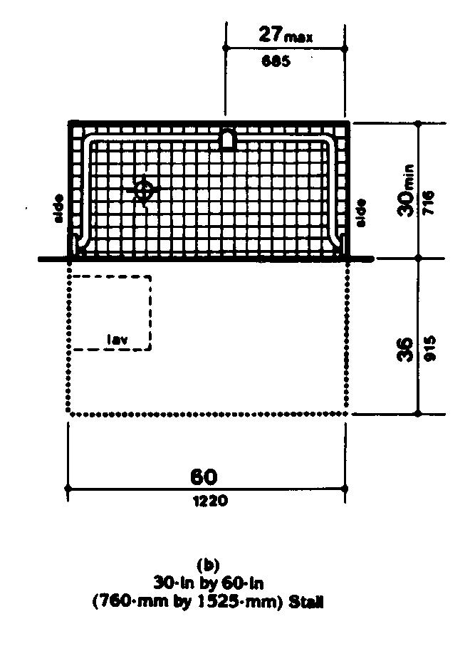
4.21.3 Seat
A seat shall be provided in shower stalls 36 in by 36 in (915 mm by 915 mm) and shall be as shown in Fig. 36. The seat shall be mounted 17 in to 19 in (430 mm to 485 mm) from the bathroom floor and shall extend the full depth of the stall. The seat shall be on the wall opposite the controls. The structural strength of seats and their attachments shall comply with 4.26.3.
4.21.4 Grab Bars
Grab bars complying with 4.26 shall be provided as shown in Fig. 37.
4.21.5 Controls
Faucets and other controls complying with 4.27.4 shall be located as shown in Fig. 37. In shower stalls 36 in by 36 in (915 mm by 915 mm), all controls, faucets, and the shower unit shall be mounted on the side wall opposite the seat.
4.21.6 Shower Unit
A shower spray unit with a hose at least 60 in (1525 mm) long that can be used as a fixed shower head or as a hand-held shower shall be provided.
EXCEPTION: In unmonitored facilities where vandalism is a consideration, a fixed shower head mounted at 48 in (1220 mm) above the shower floor may be used in lieu of a hand-held shower head.
4.21.7 Curbs
If provided, curbs in shower stalls 36 in by 36 in (915 mm by 915 mm) shall be no higher than 1/2 in (13 mm). Shower stalls that are 30 in by 60 in (760 mm by 1525 mm) shall not have curbs.
4.21.8 Shower Enclosures
If provided, enclosures for shower stalls shall not obstruct controls or obstruct transfer from wheelchairs onto shower seats.
4.22 Toilet Rooms
4.22.1 Minimum Number
Toilet facilities required to be accessible by 4.1 shall comply with 4.22. Accessible toilet rooms shall be on an accessible route.
4.22.2 Doors
All doors to accessible toilet rooms shall comply with 4.13. Doors shall not swing into the clear floor space required for any fixture.
4.22.3 Clear Floor Space
The accessible fixtures and controls required in 4.22.4, 4.22.5, 4.22.6, and 4.22.7 shall be on an accessible route. An unobstructed turning space complying with 4.2.3 shall be provided within an accessible toilet room. The clear floor space at fixtures and controls, the accessible route, and the turning space may overlap.
EXCEPTION: In toilet rooms with only one water closet and one lavatory, a clear floor space of 30 in by 60 in (815 mm by 1525 mm) may be used in lieu of the unobstructed turning space.
4.22.4 Water Closets
If toilet stalls are provided, then at least one shall comply with 4.17; its water closet shall comply with 4.16. If water closets are not in stalls, then at least one shall comply with 4.16.
4.22.5 Urinals
If urinals are provided, then at least one shall comply with 4.18.
4.22.6 Lavatories And Mirrors
If lavatories and mirrors are provided, then at least one of each shall comply with 4.19.
4.22.7 Controls And Dispensers
If controls, dispensers, receptacles, or other equipment is provided, then at least one of each shall be on an accessible route and shall comply with 4.27.
4.23 Bathrooms, Bathing Facilities, And Shower Rooms
4.23.1 Minimum Number
Bathrooms, bathing facilities, or shower rooms required to be accessible by 4.1 shall comply with 4.23 and shall be on an accessible route. For adaptable bathrooms in accessible dwelling units, see 4.34.5.
4.23.2 Doors
Doors to accessible bathrooms shall comply with 4.13. Doors shall not swing into the floor space required for any fixture.
4.23.3 Clear Floor Space
The accessible fixtures and controls required in 4.23.4, 4.23.5, 4.23.6, 4.23.7, 4.23.8, and 4.23.9 shall be on an accessible route. An unobstructed turning space complying with 4.2.3 shall be provided within an accessible bathroom. The clear floor spaces at fixtures and controls, the accessible route, and the turning space may overlap.
EXCEPTION: In bathrooms with only one water closet, one lavatory, and one bathtub or shower, a clear floor space of 30 in by 60 in (760 mm by 1525 mm) may be used in lieu of the unobstructed turning space.
4.23.4 Water Closets
If toilet stalls are provided, then at least one shall comply with 4.17; its water closet shall comply with 4.16. If water closets are not in stalls, then at least one shall comply with 4.16.
4.23.5 Urinals
If urinals are provided, then at least one shall comply with 4.18.
4.23.6 Lavatories And Mirrors
If lavatories and mirrors are provided, then at least one of each shall comply with 4.19.
4.23.7 Controls And Dispensers
If controls, dispensers, receptacles, or other equipment is provided, then at least one of each shall be on an accessible route and shall comply with 4.27.
4.23.8 Bathing And Shower Facilities
If tubs or showers are provided, then at least one accessible tub that complies with 4.20 or at least one accessible shower that complies with 4.21 shall be provided.
4.23.9* Medicine Cabinets
If medicine cabinets are provided, at least one shall be located with a usable shelf no higher than 44 in (1120 mm) above the floor space. The floor space shall comply with 4.2.4.
4.24 Sinks
4.24.1 General
Sinks required to be accessible by 4.1 shall comply with 4.24. Sinks in kitchens of accessible dwelling units shall comply with 4.34.6.5.
4.24.2 Height
Sinks shall be mounted with the counter or rim no higher than 34 in (865 mm) from the floor.
4.24.3 Knee Clearance
Knee clearance that is at least 27 in (685 mm) high, 30 in (760 mm) wide, and 19 in (485 mm) deep shall be provided underneath sinks.
4.24.4 Depth
Each sink shall be a maximum of 6-1/2 in (165 mm) deep.
4.24.5 Clear Floor Space
A clear floor space at least 30 in by 48 in (760 mm by 1220 mm) complying with 4.2.4 shall be provided in front of a sink to allow forward approach. The clear floor space shall be on an accessible route and shall extend a maximum of 19 in (485 mm) underneath the sink (see Fig. 32).
4.24.6 Exposed Pipes And Surfaces
Hot water and drain pipes exposed under sinks shall be insulated or otherwise covered. There shall be no sharp or abrasive surfaces under sinks.
4.24.7 Faucets
Faucets shall comply with 4.27.4. Lever-operated, push-type, touch-type, or electronically controlled mechanisms are acceptable designs.
4.25 Storage
4.25.1 General
Fixed storage facilities such as cabinets, shelves, closets, and drawers required to be accessible by 4.1 shall comply with 4.25.
4.25.2 Clear Floor Space
A clear floor space at least 30 in by 48 in (760 mm by 1220 mm) complying with 4.2.4 that allows either a forward or parallel approach by a person using a wheelchair shall be provided at accessible storage facilities.
4.25.3 Height
Accessible storage spaces shall be within at least one of the reach ranges specified in 4.2.5 and 4.2.6. Clothes rods shall be a maximum of 54 in (1370 mm) from the floor (see Fig. 38).
4.25.4 Hardware
Hardware for accessible storage facilities shall comply with 4.27.4. Touch latches and U-shaped pulls are acceptable.
4.26 Handrails, Grab Bars, And Tub And Shower Seats
4.26.1* General
All handrails, grab bars, and tub and shower seats required to be accessible by 4.1, 4.8, or 4.9 shall comply with 4.26.
4.26.2* Size And Spacing Of Grab Bars And Handrails
The diameter or width of the gripping surfaces of a handrail or grab bar shall be 1-1/4 in to 1-1/2 in (32 mm to 38 mm), or the shape shall provide an equivalent gripping surface. If handrails or grab bars are mounted adjacent to a wall, the space between the wall and the grab bar shall be 1-1/2 in (38 mm) (see Fig. 39(a), (b), and (c)). Handrails may be located in a recess if the recess is a maximum of 3 in (75 mm) deep and extends at least 18 in (455 mm) above the top of the rail (see Fig. 39(d)).
4.26.3 Structural Strength
The structural strength of grab bars, tub and shower seats, fasteners, and mounting devices shall meet the following specification:
- (1) Bending stress in a grab bar or seat induced by the maximum bending moment from the application of 250 lbf (1112N) shall be less than the allowable stress for the material of the grab bar or seat.
- (2) Shear stress induced in a grab bar or seat by the application of 250 lbf (1112N) shall be less than the allowable shear stress for the material of the grab bar or seat. If the connection between the grab bar or seat and its mounting bracket or other support is considered to be fully restrained, then direct and torsional shear stresses shall be totaled for the combined shear stress, which shall not exceed the allowable shear stress.
- (3) Shear force induced in a fastener or mounting device from the application of 250 lbf (1112N) shall be less than the allowable lateral load of either the fastener or mounting device or the supporting structure, whichever is the smaller allowable load.
- (4) Tensile force induced in a fastener by a direct tension force of 250 lbf (1112N) plus the maximum moment from the application of 250 lbf (1112N) shall be less than the allowable withdrawal and the supporting structure.
- (5) Grab bars shall not rotate within their fittings.
4.26.4 Eliminating Hazards
A handrail or grab bar and any wall or other surface adjacent to it shall be free of any sharp or abrasive elements. Edges shall have a minimum radius of 1/8 in (3.2 mm).
4.27 Controls And Operating Mechanisms
4.27.1 General
Controls and operating mechanisms required to be accessible by 4.1 shall comply with 4.27.
4.27.2 Clear Floor Space
Clear floor space complying with 4.2.4 that allows a forward or a parallel approach by a person using a wheelchair shall be provided at controls, dispensers, receptacles, and other operable equipment.
4.27.3* Height
The highest operable part of all controls, dispensers, receptacles, and other operable equipment shall be placed within at least one of the reach ranges specified in 4.2.5 and 4.2.6. Except where the use of special equipment dictates otherwise, electrical and communications system receptacles on walls shall be mounted no less than 15 in (380 mm) above the floor.
4.27.4 Operation
Controls and operating mechanisms shall be operable with one hand and shall not require tight grasping, pinching, or twisting of the wrist. The force required to activate controls shall be no greater than 5 lbf (22.2 N).
4.28 Alarms
4.28.1 General
Alarm systems required to be accessible by 4.1 shall comply with 4.28.
4.28.2* Audible Alarms
If provided, audible emergency alarms shall produce a sound that exceeds the prevailing equivalent sound level in the room or space by at least 15 decibels or exceeds any maximum sound level with a duration of 30 seconds by 5 decibels, whichever is louder. Sound levels for alarm signals shall not exceed 120 decibels.
4.28.3* Visual Alarms
If provided, electrically powered internally illuminated emergency exit signs shall flash as a visual emergency alarm in conjunction with audible emergency alarms. The flashing frequency of visual alarm devices shall be less than 5 Hz. If such alarms use electricity from the building as a power source, then they shall be installed on the same system as the audible emergency alarms.
EXCEPTIONS:
- (1) Visual alarm devices that are mounted adjacent to emergency exit signs may be used in lieu of flashing exit signs.
- (2) Specialized systems utilizing advanced technology may be substituted for the visual systems specified above if equivalent protection is afforded handicapped users of the building or facility.
4.28.4* Auxiliary Alarms
Accessible sleeping accommodations shall have a visual alarm connected to the building emergency alarm system or shall have a standard 110-volt electrical receptacle into which such an alarm could be connected. Instructions for use of the auxiliary alarm or connection shall be provided.
4.29 Tactile Warnings
4.29.1 General
Tactile warnings required to be accessible by 4.1 shall comply with 4.29.
4.29.2* Tactile Warnings On Walking Surfaces
(Reserved).
4.29.3* Tactile Warnings On Doors To Hazardous Areas
Doors that lead to areas that might prove dangerous to a blind person (for example, doors to loading platforms, boiler rooms, stages, and the like) shall be made identifiable to the touch by a textured surface on the door handle, knob, pull or other operating hardware. This textured surface may be made by knurling or roughing or by a material applied to the contact surface. Such textured surfaces shall not be provided for emergency exit doors or any doors other than those to hazardous areas.
4.29.4 Tactile Warnings At Stairs
(Reserved).
4.29.5* Tactile Warnings At Hazardous Vehicular Areas
(Reserved).
4.29.6* Tactile Warnings At Reflecting Pools
(Reserved).
4.29.7* Standardization
Textured surfaces for tactile door warnings shall be standard within a building, facility, site, or complex of buildings.
4.30 Signage
4.30.1* General
Signage required to be accessible by 4.1 shall comply with 4.30.
4.30.2* Character Proportion
Letters and numbers on signs shall have a width-to-height ratio between 3:5 and 1:1 and a stroke width-to-height ratio between 1:5 and 1:10.
4.30.3* Color Contrast
Characters and symbols shall contrast with their background - either light characters on a dark background or dark characters on a light background.
4.30.4* Raised Characters Or Symbols
Letters and numbers on signs shall be raised 1/32 in (0.8 mm) minimum and shall be sans serif characters. Raised characters or symbols shall be at least 5/8 in (16 mm) high, but no higher than 2 in (50 mm). Symbols or pictographs on signs shall be raised 1/32 in (0.8 mm) minimum.
4.30.5 Symbols Of Accessibility
Accessible facilities required to be identified by 4.1, shall use the international symbol of accessibility. The symbol shall be displayed as shown in Fig. 43.
4.30.6 Mounting Location And Height
Interior signage shall be located alongside the door on the latch side and shall be mounted at a height of between 54 in and 66 in (1370 mm and 1675 mm) above the finished floor.
4.31 Telephones
4.31.1 General
Public telephones required to be accessible by 4.1 shall comply with 4.31.
4.31.2 Clear Floor Or Ground Space
A clear floor or ground space at least 30 in by 48 in (760 mm by 1220 mm) that allows either a forward or parallel approach by a person using a wheelchair shall be provided at telephones (see Fig. 44). The clear floor or ground space shall comply with 4.2.4. Bases, enclosures, and fixed seats shall not impede approaches to telephones by people who use wheelchairs.
4.31.3* Mounting Height
The highest operable part of the telephone shall be within the reach ranges specified in 4.2.5 or 4.2.6.
4.31.4 Protruding Objects
Telephones shall comply with 4.4.
4.31.5* Equipment For Hearing Impaired People
Telephones shall be equipped with a receiver that generates a magnetic field in the area of the receiver cap. Volume controls shall be provided in accordance with 4.1.2.
4.31.6 Controls
Telephones shall have pushbutton controls where service for such equipment is available.
4.31.7 Telephone Books
Telephone books, if provided, shall be located in a position that complies with the reach ranges specified in 4.2.5 and 4.2.6.
4.31.8 Cord Length
The cord from the telephone to the handset shall be at least 29 in (735 mm) long.
4.32 Seating, Tables, And Work Surfaces
4.32.1 Minimum Number
Fixed or built-in seating, tables, or work surfaces required to be accessible by 4.1 shall comply with 4.32.
4.32.2 Seating
If seating spaces for people in wheelchairs are provided at tables, counters, or work surfaces, clear floor space complying with 4.2.4 shall be provided. Such clear floor space shall not overlap knee space by more than 19 in (485 mm) (see Fig. 45).
4.32.3 Knee Clearances
If seating for people in wheelchairs is provided at tables, counters, and work surfaces, knee spaces at least 27 in (685 mm) high, 30 in (760 mm) wide, and 19 in (485 mm) deep shall be provided (see Fig. 45).
4.32.4* Height Of Work Surfaces
The tops of tables and work surfaces shall be from 28 in to 34 in (710 mm to 865 mm) from the floor or ground.
4.33 Assembly Areas
4.33.1 Minimum Number
Assembly and associated areas required to be accessible by 4.1 shall comply with 4.33.
4.33.2* Size Of Wheelchair Locations
Each wheelchair location shall provide minimum clear ground or floor spaces as shown in Fig. 46.
4.33.3* Placement Of Wheelchair Locations
Wheelchair areas shall be an integral part of any fixed seating plan and shall be dispersed throughout the seating area. They shall adjoin an accessible route that also serves as a means of egress in case of emergency and shall be located to provide lines of sight comparable to those for all viewing areas.
EXCEPTION: Accessible viewing positions may be clustered for bleachers, balconies, and other areas having sight lines that require slopes of greater than 5 percent. Equivalent accessible viewing positions may be located on levels having accessible egress.
4.33.4 Surfaces
The ground or floor at wheelchair locations shall be level and shall comply with 4.5.
4.33.5 Access To Performing Areas
An accessible route shall connect wheelchair seating locations with performing areas, including stages, arena floors, dressing rooms, locker rooms, and other spaces used by performers.
4.33.6* Placement Of Listening Systems
If the listening system provided serves individual fixed seats, then such seats shall be located within a 50 ft (15 m) viewing distance of the stage or playing area and shall have a complete view of the stage or playing area.
4.33.7* Types Of Listening Systems
Audio loops and radio frequency systems are two acceptable types of listening systems.
4.34 Dwelling Units
4.34.1 General
The requirements of 4.34 apply to dwelling units required to be accessible by 4.1.
4.34.2* Minimum Requirements
An accessible dwelling unit shall be on an accessible route. An accessible dwelling unit shall have the following accessible elements and spaces as a minimum:
- (1) Common spaces and facilities serving individual accessible dwelling units (for example, entry walks, trash disposal facilities, and mail boxes) shall comply with 4.2 through 4.33.
- (2) Accessible spaces shall have maneuvering space complying with 4.2.2 and 4.2.3 and surfaces complying with 4.5.
- (3) At least one accessible route complying with 4.3 shall connect the accessible entrances with all accessible spaces and elements within the dwelling units.
- (4) See 4.1.1(5)(d) --- Parking.
- (5) Removed and reserved.
- (6) Doors to and in accessible spaces that are intended for passage shall comply with 4.13, except that the provisions of 4.13.9 apply only to the doors at accessible entrances to the unit itself.
- (7) At least one accessible entrance to the dwelling unit shall comply with 4.14.
- (8) Storage in accessible spaces in dwelling units, including cabinets, shelves, closets, and drawers, shall comply with 4.25.
- (9) All controls in accessible spaces shall comply with 4.27. Those portions of heating, ventilating, and air conditioning equipment requiring regular, periodic maintenance and adjustment by the resident of a dwelling shall be accessible to people in wheelchairs. If air distribution registers must be placed in or close to ceilings for proper air circulation, this specification shall not apply to the registers.
- (10) Emergency alarms as required by 4.1 and complying with 4.28.4 shall be provided in the dwelling unit.
- (11) Removed and reserved.
- (12) At least one full bathroom shall comply with 4.34.5. A full bathroom shall include a water closet, a lavatory, and a bathtub or a shower.
- (13) The kitchen shall comply with 4.34.6.
- (14) If laundry facilities are provided, they shall comply with 4.34.7.
- (15) The following spaces shall be accessible and shall be on an accessible route:
- (a) The living area.
- (b) The dining area.
- (c) The sleeping area, or the bedroom in one bedroom dwelling units, or at least two bedrooms or sleeping spaces in dwelling units with two or more bedrooms.
- (d) Patios, terraces, balconies, carports, and garages, if provided with the dwelling unit.
4.34.3 Adaptability
The specifications for 4.34.5 and 4.34.6 include the concept of adaptability. Accessible dwelling units may be designed for either permanent accessibility or adaptability.
4.34.4 Consumer Information
To ensure that the existence of adaptable features will be known to the owner or occupant of a dwelling, the following consumer information shall be provided in each adaptable dwelling unit available for occupancy:
- (1) Notification of the alternate heights available for the kitchen counter and sink, and the existence of removable cabinets and bases, if provided, under counters, sinks, and lavatories.
- (2) Notification of the provisions for the installation of grab bars at toilets, bathtubs, and showers.
- (3) Notification that the dwelling unit is equipped to have a visual emergency alarm installed.
- (4) Identification of the location where information and instructions are available for changing the height of counters, removing cabinets and bases, installing a visual emergency alarm system, and installing grab bars.
- (5) Notification that the dwelling unit has been designed in accordance with this Uniform Federal Accessibility Standards.
In addition, the parties who will be responsible for making adaptations shall be provided with the following information:
- (1) Instructions for adjusting or replacing kitchen counter and sink heights and for removing cabinets.
- (2) A scale drawing showing methods and locations for the installation of grab bars.
- (3) A scale drawing showing the location of adjustable or replaceable counter areas and removable cabinets.
- (4) Identification of the location of any equipment and parts required for adjusting or replacing counter tops, cabinets, and sinks.
- (5) Instructions for installing a visual emergency alarm system, if the dwelling unit is equipped for such an installation.
4.34.5* Bathrooms
Accessible or adaptable bathrooms shall be on an accessible route and shall comply with the requirements of 4.34.5.
4.34.5.1 Doors
Doors shall not swing into the clear floor space required for any fixture.
4.34.5.2 Water Closets
- (1) Clear floor space at the water closet shall be as shown in Fig. 47(a). The water closet may be located with the clear area at either the right or left side of the toilet.
- (2) The height of the water closet shall be at least 15 in (380 mm), and no more than 19 in (485 mm), measured to the top of the toilet seat.
- (3) Structural reinforcement or other provisions that will allow installation of grab bars shall be provided in the locations shown in Fig. 47(b). If provided, grab bars shall be installed as shown in Fig. 29 and shall comply with 4.26.
- (4) The toilet paper dispenser shall be installed within reach as shown in Fig. 47(b).
Note: The hatched areas are reinforced to receive grab bars.
4.34.5.3 Lavatory, Mirrors, And Medicine Cabinets
- (1) The lavatory and mirrors shall comply with 4.22.6.
- (2) If a cabinet is provided under the lavatory in adaptable bathrooms, then it shall be removable to provide the clearances specified in 4.22.6.
- (3) If a medicine cabinet is provided above the lavatory, then the bottom of the medicine cabinet shall be located with a usable shelf no higher than 44 in (1120 mm) above the floor.
4.34.5.4 Bathtubs
If a bathtub is provided, then it shall have the following features:
- (1) Floor space. Clear floor space at bathtubs shall be as shown in Fig. 33.
- (2) Seat. An in-tub seat or a seat at the head end of the tub shall be provided as shown in Fig. 33 and 34. The structural strength of seats and their attachments shall comply with 4.26.3. Seats shall be mounted securely and shall not slip during use.
- (3) Grab bars. Structural reinforcement or other provisions that will allow installation of grab bars shall be provided in the locations shown in Fig. 48. If provided, grab bars shall be installed as shown in Fig. 34 and shall comply with 4.26.
- (4) Controls. Faucets and other controls shall be located as shown in Fig. 34 and shall comply with 4.27.4.
- (5) Shower unit. A shower spray unit with a hose at least 60 in (1525 mm) long that can be used as a fixed shower head or as a hand-held shower shall be provided.
4.34.5.5 Showers
If a shower is provided, it shall have the following features:
- (1) Size and clearances. Shower stall size and clear floor space shall comply with either Fig. 35(a) or (b). The shower stall in Fig. 35(a) shall be 36 in by 36 in (915 mm by 915 mm). The shower stall in Fig. 35(b) will fit into the same space as a standard 60 in (1525 mm) long bathtub.
- (2) Seat. A seat shall be provided in the shower stall in Fig. 35(a) as shown in Fig. 36. The seat shall be 17 in to 19 in (430 mm to 485 mm) high measured from the bathroom floor and shall extend the full depth of the stall. The seat shall be on the wall opposite the controls. The structural strength of seats and their attachments shall comply with 4.26.3. Seats shall be mounted securely and shall not slip during use.
- (3) Grab bars. Structural reinforcement or other provisions that will allow installation of grab bars shall be provided in the locations shown in Fig. 49. If provided, grab bars shall be installed as shown in Fig. 37 and shall comply with 4.26.
- (4) Controls. Faucets and other controls shall be located as shown in Fig. 37 and shall comply with 4.27.4. In the shower stall in Fig. 35(a), all controls, faucets, and the shower unit shall be mounted on the side wall opposite the seat.
- (5) Shower unit. A shower spray unit with a hose at least 60 in (1525 mm) long that can be used as a fixed shower head at various heights or as a hand-held shower shall be provided.
4.34.5.6 Bathtub And Shower Enclosures
Enclosures for bathtubs or shower stalls shall not obstruct controls or transfer from wheelchairs onto shower or bathtub seats. Enclosures on bathtubs shall not have tracks mounted on their rims.
4.34.5.7 Clear Floor Space
Clear floor space at fixtures may overlap.
4.34.6 Kitchens
Accessible or adaptable kitchens and their components shall be on an accessible route and shall comply with the requirements of 4.34.6.
4.34.6.1* Clearance
Clearances between all opposing base cabinets, counter tops, appliances, or walls shall be 40 in (1015 mm) minimum, except in U-shaped kitchens, where such clearance shall be 60 in (1525 mm) minimum.
4.34.6.2 Clear Floor Space
A clear floor space at least 30 in by 48 in (760 mm by 1220 mm) complying with 4.2.4 that allows either a forward or a parallel approach by a person in a wheelchair shall be provided at all appliances in the kitchen, including the range or cooktop, oven, refrigerator/freezer, dishwasher, and trash compactor. Laundry equipment located in the kitchen shall comply with 4.34.7.
4.34.6.3 Controls
All controls in kitchens shall comply with 4.27.
4.34.6.4 Work Surfaces
At least one 30 in (760 mm) section of counter shall provide a work surface that complies with the following requirements (see Fig. 50):
- (1) The counter shall be mounted at a maximum height of 34 in (865 mm) above the floor, measured from the floor to the top of the counter surface, or shall be adjustable or replaceable as a unit to provide alternative heights of 28 in, 32 in, and 36 in (710 mm, 815 mm, and 915 mm), measured from the top of the counter surface.
- (2) Base cabinets, if provided, shall be removable under the full 30 in (760 mm) minimum frontage of the counter. The finished floor shall extend under the counter to the wall.
- (3) Counter thickness and supporting structure shall be 2 in (50 mm) maximum over the required clear area.
- (4) A clear floor space 30 in by 48 in (760 mm by 1220 mm) shall allow a forward approach to the counter. Nineteen inches (485 mm) maximum of the clear floor space may extend underneath the counter. The knee space shall have a minimum clear width of 30 in (760 mm) and a minimum clear depth of 19 in (485 mm).
- (5) There shall be no sharp or abrasive surfaces under such counters.
4.34.6.5* Sink
The sink and surrounding counter shall comply with the following requirements (see Fig. 51):
- (1) The sink and surrounding counter shall be mounted at a maximum height of 34 in (865 mm) above the floor, measured from the floor to the top of the counter surface, or shall be adjustable or replaceable as a unit to provide alternative heights of 28 in, 32 in, and 36 in (710 mm, 815 mm, and 915 mm), measured from the floor to the top of the counter surface or sink rim. The total width of sink and counter area shall be 30 in (760 mm).
- (2) Rough-in plumbing shall be located to accept connections of supply and drain pipes for sinks mounted at the height of 28 in (710 mm).
- (3) The depth of a sink bowl shall be no greater than 6-1/2 in (165 mm). Only one bowl of double- or triple-bowl sinks needs to meet this requirement.
- (4) Faucets shall comply with 4.27.4. Lever-operated or push-type mechanisms are two acceptable designs.
- (5) Base cabinets, if provided, shall be removable under the full 30 in (760 mm) minimum frontage of the sink and surrounding counter. The finished flooring shall extend under the counter to the wall.
- (6) Counter thickness and supporting structure shall be 2 in (50 mm) maximum over the required clear space.
- (7) A clear floor space 30 in by 48 in (760 mm by 1220 mm) shall allow forward approach to the sink. Nineteen inches (485 mm) maximum of the clear floor space may extend underneath the sink. The knee space shall have a clear width of 30 in (760 mm) and a clear depth of 19 in (485 mm).
- (8) There shall be no sharp or abrasive surfaces under sinks. Hot water and drain pipes under sinks shall be insulated or otherwise covered.
4.34.6.6* Ranges And Cooktops
Ranges and cooktops shall comply with 4.34.6.2 and 4.34.6.3. If ovens or cooktops have knee spaces underneath, then they shall be insulated or otherwise protected on the exposed contact surfaces to prevent burns, abrasions, or electrical shock. The clear floor space may overlap the knee space, if provided, by 19 in (485 mm) maximum. The location of controls for ranges and cook-tops shall not require reaching across burners.
4.34.6.7* Ovens
Ovens shall comply with 4.34.6.2 and 4.34.6.3. Ovens shall be of the self-cleaning type or be located adjacent to an adjustable height counter with knee space below (see Fig. 52). For side-opening ovens, the door latch side shall be next to the open counter space, and there shall be a pull-out shelf under the oven extending the full width of the oven and pulling out not less than 10 in (255 mm) when fully extended. Ovens shall have controls on front panels; they may be located on either side of the door.
4.34.6.8* Refrigerator/Freezer
Refrigerator/freezers shall comply with 4.34.6.3. Provision shall be made for refrigerators which are:
- (1) Of the vertical side-by-side refrigerator/freezer type; or
- (2) Of the over-and-under type and meet the following requirements:
- (a) Have at least 50 percent of the freezer space below 54 in (1370 mm) above the floor.
- (b) Have 100 percent of the refrigerator space and controls below 54 in (1370 mm).
Freezers with less than 100 percent of the storage volume within the limits specified in 4.2.5 or 4.2.6 shall be the self-defrosting type.
4.34.6.9 Dishwashers
Dishwashers shall comply with 4.34.6.2 and 4.34.6.3. Dishwashers shall have all rack space accessible from the front of the machine for loading and unloading dishes.
4.34.6.10* Kitchen Storage
Cabinets, drawers, and shelf areas shall comply with 4.25 and shall have the following features:
- (1) Maximum height shall be 48 in (1220 mm) for at least one shelf of all cabinets and storage shelves mounted above work counters (see Fig. 50).
- (2) Door pulls or handles for wall cabinets shall be mounted as close to the bottom of cabinet doors as possible. Door pulls or handles for base cabinets shall be mounted as close to the top of cabinet doors as possible.
4.34.7 Laundry Facilities
If laundry equipment is provided within individual accessible dwelling units, or if separate laundry facilities serve one or more accessible dwelling units, then they shall meet the requirements of 4.34.7.1 through 4.34.7.3.
4.34.7.1 Location
Laundry facilities and laundry equipment shall be on an accessible route.
4.34.7.2 Washing Machines And Clothes Dryers
Washing machines and clothes dryers in common use laundry rooms shall be front loading.
4.34.7.3 Controls
Laundry equipment shall comply with 4.27.
5. Restaurants And Cafeterias
5.1 General
In addition to the requirements of 4.1 to 4.33, the design of at least 5 percent of all fixed seating or tables in a restaurant or cafeteria shall comply with 4.32. Access aisles between tables shall comply with 4.3. Where practical, accessible tables should be distributed throughout the space or facility. In restaurants or cafeterias where there are mezzanine levels, loggias, or raised platforms, accessibility to all such spaces is not required providing that the same services and decorative character are provided in spaces located on accessible routes.
5.2 Food Service Lines
Food service lines shall have a minimum clear width of 36 in (915 mm), with a preferred clear width of 42 in (1065 mm) where passage of stopped wheelchairs by pedestrians is desired. Tray slides shall be mounted no higher than 34 in (865 mm) above the floor. If self-service shelves are provided, a reasonable portion must be within the ranges shown in Fig. 53.
5.3 Tableware Areas
Install tableware, dishware, condiment, food and beverage display shelves, and dispensing devices in compliance with 4.2 (see Fig. 54).
5.4 Vending Machines
Install vending machines in compliance with 4.27.
6. Health Care
6.1 General
In addition to the requirements of 4.1 to 4.33, Health Care buildings and facilities shall comply with 6.
6.2 Entrances
At least one accessible entrance that complies with 4.14 shall be protected from the weather by canopy or roof overhang. Such entrances shall incorporate a passenger loading zone that complies with 4.6.5 (see 4.13.6).
6.3 Patient Bedrooms
Provide accessible patient bedrooms in compliance with 4. Accessible patient bedrooms shall comply with the following:
- (1) Each bedroom shall have a turning space that complies with 4.2.3, and preferably that is located near the entrance.
- (2) Each one-bed room shall have a minimum clear floor space of 36 in (915 mm) along each side of the bed, and 42 in (1065 mm) between the foot of the bed and the wall.
- (3) Each two-bed room shall have a minimum clear floor space of 42 in (1065 mm), preferably 48 in (1220 mm), between the foot of the bed and the wall; 36 in (915 mm) between the side of the bed and the wall; and 48 in (1220 mm) between beds.
- (4) Each four-bed room shall have a minimum clear floor space of 48 in (1220 mm) from the foot of the bed to the foot of the opposing bed; 36 in (915 mm) between the side of the bed and the wall; and 48 in (1220 mm) between beds.
- (5) Each bedroom shall have a door that complies with 4.13.
6.4 Patient Toilet Rooms
Provide each patient bedroom that is required to be accessible with an accessible toilet room that complies with 4.22 or 4.23.
7. Mercantile
7.1 General
In addition to the requirements of 4.1 to 4.33, the design of all areas used for business transactions with the public shall comply with 7.
7.2 Service Counters
Where service counters exceeding 36 in (915 mm) in height are provided for standing sales or distribution of goods to the public, an auxiliary counter or a portion of the main counter shall be provided with a maximum height of between 28 in to 34 in (710 mm to 865 mm) above the floor in compliance with 4.32.4.
7.3 Check-Out Aisles
At least one accessible check-out aisle shall be provided in buildings or facilities with check-out aisles. Clear aisle width shall comply with 4.2.1 and maximum adjoining counter height shall not exceed 36 in (915 mm) above the floor.
7.4 Security Bollards
Any device used to prevent the removal of shopping carts from store premises shall not prevent access or egress to those in wheelchairs. An alternate entry that is equally convenient to that provided for the ambulatory population is acceptable.
8. Libraries
8.1 General
In addition to the requirements of 4.1 to 4.33, the design of all public areas of a library shall comply with 8, including reading and study areas, stacks, reference rooms, reserve areas, and special facilities or collections. As provided, elements such as public toilet rooms, telephones, and parking shall be accessible.
8.2 Reading And Study Areas
At least 5 percent or a minimum of one of each element of fixed seating, tables, or study carrels shall comply with 4.2 and 4.32. Clearances between fixed accessible tables and study carrels shall comply with 4.3.
8.3 Check-Out Areas
At least one lane at each check-out area shall comply with 4.32. Any traffic control or book security gates or turnstiles shall comply with 4.13.
8.4 Card Catalogs
Minimum clear aisle space at card catalogs, magazine displays, or reference stacks shall comply with Fig. 55. Maximum reach height shall comply with 4.2, with a height of 48 in (1370 mm) preferred, irrespective of reach allowed.
8.5 Stacks
Minimum clear aisle width between stacks shall comply with 4.3, with a minimum clear aisle width of 42 in (1065 mm) preferred where possible. Shelf height in stack areas is unrestricted (see Fig. 56).
9. Postal Facilities
9.1 General
In addition to the requirements of 4.1 to 4.33, the design of U.S. postal facilities shall comply with the requirements of 9. In addition, employee toilet rooms, water fountains, lunchrooms, lounges, attendance-recording equipment, medical treatment rooms, emergency signals, and switches and controls shall be made accessible or adaptable in accordance with the requirements of these standards.
9.2* Post Office Lobbies
Where writing desks or tables are provided, a minimum of at least one writing desk or table that complies with 4.32 must be provided. Clear passageways in front of customer service counters shall be not less than 48 in (1220 mm) clear width to permit maneuvering of a wheelchair. Letter drops shall be mounted at heights that comply with 4.2.
- (1) All fixed partitions must be installed to withstand a 250-pound force applied at any point and from any direction. Avoid designs that call for, or may necessitate, non-fixed partitions in circulation routes of handicapped people.
- (2) Walls where handrails are provided for handicapped people must be capable of supporting handrails designed to support a 250-pound pull force in any direction.
9.3 Self-Service Postal Center
Parcel post depositories, stamp vending machines, multi-commodity vending machines, and currency-coin changing machines shall be installed so that the operating mechanisms of all machines comply with 4.2 and 4.27. All mechanisms must be installed to permit close parallel approach by a wheelchair user.
9.4 Post Office Boxes
At least 5 percent of the post office boxes in a facility shall be accessible to wheelchair users. The total number of accessible post office boxes provided shall include a representative number of each of the standard USPS boxes currently being installed. Accessible post office boxes shall be located in the second or third set of modules from the floor, approximately 12 in to 36 in (305 mm to 915 mm) above the finished floor. Aisles between post office boxes shall be a minimum of 66 in (1675 mm) clear width.
9.5 Locker Rooms
Lockers in easily accessible areas must be provided for use by handicapped people. When double-tier lockers are used, only the bottom row of lockers may be assigned for use by wheelchair users. When full length lockers are used all hooks, shelves, etc., intended for use by people in wheelchairs shall be located no higher than 48 in (1220 mm) above the finished floor. Lockers intended for use by handicapped people shall be equipped with latches and latch handles that comply with 4.27. Unobstructed aisle space in front of lockers used by handicapped people shall be a minimum of 42 in (1065 mm) clear width.
9.6 Attendance-Recording Equipment
Time clocks, card racks, log books, and other work assignment or attendance-recording equipment used by people in wheelchairs must be installed at a height no more than 48 in (1220 mm) above the finished floor. Counter space at check-in areas must be no more than 36 in (915 mm) above the finished floor.
Appendix
This appendix contains additional information that should help the designer to understand the minimum requirements of the standard or to design buildings or facilities for greater accessibility. The paragraph numbers correspond to the sections or paragraphs of the standard to which the material relates and are therefore not consecutive (for example, A4.2.1 contains additional information relevant to 4.2.1). Sections for which additional material appears in this appendix have been indicated by an asterisk.
A4.2 Space Allowances And Reach Ranges
A4.2.1 Wheelchair Passage Width
- (1) Space Requirements for Wheelchairs. Most wheelchair users need a 30 in (760 mm) clear opening width for doorways, gates, and the like, when the latter are entered head-on. If the wheelchair user is unfamiliar with a building, if competing traffic is heavy, if sudden or frequent movements are needed, or if the wheelchair must be turned at an opening, then greater clear widths are needed. For most situations, the addition of an inch of leeway on either side is sufficient. Thus, a minimum clear width of 32 in (815 mm) will provide adequate clearance. However, when an opening or a restriction in a passageway is more than 24 in (610 mm) long, it is essentially a passageway and must be at least 36 in (915 mm) wide.
- (2) Space Requirements for Use of Walking Aids. Although people who use walking aids can maneuver through clear width openings of 32 in (815 mm), they need 36 in (915 mm) wide passageways and walks for comfortable gaits. Crutch tips, often extending down at a wide angle, are a hazard in narrow passageways where they might not be seen by other pedestrians. Thus, the 36 in (915 mm) width provides a safety allowance both for the disabled person and for others.
- (3) Space Requirements for Passing. Able-bodied people in winter clothing, walking straight ahead with arms swinging, need 32 in (815 mm) of width, which includes 2 in (50 mm) on either side for sway, and another 1 in (25 mm) tolerance on either side for clearing nearby objects or other pedestrians. Almost all wheelchair users and those who use walking aids can also manage within this 32 in (815 mm) width for short distances. Thus, two streams of traffic can pass in 64 in (1625 mm) in a comfortable flow. Sixty inches (1525 mm) provide a minimum width for a somewhat more restricted flow. If the clear width is less than 60 in (1525 mm), two wheelchair users will not be able to pass but will have to seek a wider place for passing. Forty-eight inches (1220 mm) is the minimum width needed for an ambulatory person to pass a nonambulatory or semiambulatory person. Within this 48 in (1220 mm) width, the ambulatory person will have to twist to pass a wheelchair user, a person with a seeing eye dog, or a semiambulatory person. There will be little leeway for swaying or missteps (see Fig. A1).
A4.2.3 Wheelchair Turning Space
This standard specifies a minimum space of 60 in (1525 mm) diameter for a pivoting 180-degree turn of a wheelchair. This space is usually satisfactory for turning around, but many people will not be able to turn without repeated tries and bumping into surrounding objects. The space shown in Fig. A2 will allow most wheelchair users to complete U-turns without difficulty.
The space needed for a smooth U-turn in a wheelchair is 78 inches (1965 mm) minimum by 60 inches (1525 mm) minimum.
A4.2.4 Clear Floor Or Ground Space For Wheelchairs
The wheelchair and user shown in Fig. A3 represent typical dimensions for a large adult male. The space requirements in this standard are based upon maneuvering clearances that will accommodate most larger wheelchairs. Fig. A3 provides a uniform reference for design not covered by this standard.
Note: Footrests may extend further for very large people.
A4.2.5 & A4.2.6 Reach
Reach ranges for persons seated in wheelchairs may be further clarified by Fig. A3(a). These drawings approximate in the plan view information shown in Fig. 4, 5, and 6 in other views.
A4.3 Accessible Route
A4.3.1 General
- (1) Travel Distances. Many disabled person can move at only very slow speeds; for many, traveling 200 ft (61 m) could take about 2 minutes. This assumes a rate of about 1.5 ft/s (455 mm/s) on level ground. It also assumes that the traveler would move continuously. However, on trips over 100 ft (30 m), disabled people are apt to rest frequently, which substantially increases their trip times. Resting periods of 2 minutes for every 100 ft (30 m) can be used to estimate travel times for people with severely limited stamina. In inclement weather, slow progress and resting can greatly increase a disabled person's exposure to the elements.
- (2) Sites. Level, indirect routes or those with running slopes lower than 1:20 can sometimes provide more convenience than direct routes with maximum allowable slopes or with ramps.
A4.3.10 Egress
In buildings where physically handicapped people are regularly employed or are residents, an emergency management plan for their evacuation also plays an essential role in fire safety.
A4.4 Protruding Objects
A4.4.1 General
Guide dogs are trained to recognize and avoid hazards. However, most people with severe impairments of vision use the long cane as an aid to mobility. The two principal cane techniques are the touch technique, where the cane arcs from side to side and touches points outside both shoulders; and the diagonal technique, where the cane is held in a stationary position diagonally across the body with the cane tip touching or just above the ground at a point outside one shoulder and the handle or grip extending to a point outside the other shoulder. The touch technique is used primarily in uncontrolled areas, while the diagonal technique is used primarily in certain limited, controlled, and familiar environments. Cane users are often trained to use both techniques.
Potential hazardous objects are noticed only if they fall within the detection range of canes (see Fig. A4). Visually impaired people walking toward an object can detect an overhang if its lowest surface is not higher than 27 in (685 mm). When walking alongside projecting objects, they cannot detect overhangs. Since proper cane and guide dog techniques keep people away from the edge of a path or from walks, a slight overhang of no more than 4 in (100 mm) is not hazardous.
A4.5 Ground And Floor Surfaces
A4.5.1 General
Ambulant and semiambulant people who have difficulty maintaining balance and those with restricted gaits are particularly sensitive to slipping and tripping hazards. For such people, a stable and regular surface is necessary for safe walking, particularly on stairs. Wheelchairs can be propelled most easily on surfaces that are hard, stable, and regular. Soft, loose surfaces such as shag carpet, loose sand, and wet clay, and irregular surfaces, such as cobblestones, can significantly impede wheelchair movement.
Slip resistance is based on the frictional force necessary to keep a shoe heel or crutch tip from slipping on a walking surface under the conditions of use likely to be found on the surface. Although it is known that the static coefficient of friction is the basis of slip resistance, there is not as yet a generally accepted method to evaluate the slip resistance of walking surfaces.
Cross slopes on walks and ground or floor surfaces can cause considerable difficulty in propelling a wheelchair in a straight line.
A4.5.3 Carpet
Much more needs to be done in developing both quantitative and qualitative criteria for carpeting. However, certain functional characteristics are well established. When both carpet and padding are used, it is desirable to have minimum movement (preferably none) between the floor and the pad and the pad and the carpet, which would allow the carpet to hump or warp. In heavily trafficked areas, a thick soft (plush) pad or cushion, particularly in combination with long carpet pile, makes it difficult for individuals in wheelchairs and those with other ambulatory disabilities to get about. This should not preclude their use in specific areas where traffic is light. Firm carpeting can be achieved through proper selection and combination of pad and carpet, sometimes with the elimination of the pad or cushion, and with proper installation.
A4.6 Parking And Passenger Loading Zones
A4.6.3 Parking Spaces
High-top vans, which disabled people or transportation services often use, require higher clearances in parking garages than automobiles. When optional van spaces are provided within a garage, only the spaces themselves and a vehicle route to them require the specified clearances.
A4.6.4 Signage
Signs designating parking places for disabled people can be seen from a driver's seat if the signs are mounted high enough above the ground and located at the front of a parking space.
A4.8 Ramps
A4.8.1 General
Ramps are essential for wheelchair users if elevators or lifts are not available to connect different levels. However, some people who use walking aids have difficulty with ramps and prefer stairs.
A4.8.2 Slope And Rise
The ability to manage an incline is related to both its slope and its length. Wheelchair users with disabilities affecting arms or with low stamina have serious difficulty using inclines. Most ambulatory people and most people who use wheelchairs can manage a slope of 1:16. Many people cannot manage a slope of 1:12 for 30 ft (9 m). Many people who have difficulty negotiating very long ramps at relatively shallow slopes can manage very short ramps at steeper slopes.
A4.8.5 Handrails
The requirements for stair and ramp handrails in this standard are for adults. When children are principal users in a building or facility, a second set of handrails at an appropriate height can assist them and aid in preventing accidents.
A4.10 Elevators
A4.10.6 Door Protective And Reopening Device
The required door reopening device would hold the door open for 20 seconds if the doorway remains unobstructed. After 20 seconds, the door may begin to close. However, if designed in accordance with ANSI A17.1-1978, the door closing movement could still be stopped if a person or object exerts sufficient force at any point on the door edge.
A4.10.7 Door And Signal Timing For Hall Calls
This paragraph allows variation in the location of call buttons, advance time for warning signals, and the door-holding period used to meet the time requirement.
A4.10.12 Car Controls
Industry-wide standardization of elevator control panel design would make all elevators significantly more convenient for use by people with severe visual impairments.
In many cases, it will be possible to locate the highest control on elevator panels with 48 in (1220 mm) from the floor.
A4.10.13 Car Position Indicators
A special button may be provided that would activate the audible signal within the given elevator only for the desired trip, rather than maintaining the audible signal in constant operation.
A4.10.14 Emergency Communications
A device that required no handset is easier to use by people who have difficulty reaching.
A4.11 Platform Lifts
Platform lifts include porch lifts and other devices used for short-distance, vertical transportation of people in wheelchairs. At the present time, generally recognized safety standards for such lifts have not been developed. Care should be taken in selecting and installing lifts to ensure that they are free from hazards to users or to other individuals who may be in the vicinity where they are being operated.
A4.13 Doors
A4.13.8 Thresholds At Doorways
Thresholds and surface height changes in doorways are particularly inconvenient for wheelchair users who also have low stamina or restrictions in arm movement, because complex maneuvering is required to get over the level change while operating the door.
A4.13.9 Door Hardware
Some disabled persons must push against a door with their chair or walker to open it. Applied kickplates on doors with closers can reduce required maintenance by withstanding abuse from wheelchairs and canes. To be effective, they should cover the door width, less approximately 2 in (51 mm), up to a height of 16 in (405 mm) form its bottom edge and be centered across the top.
A4.13.10 Door Closers
Closers with delayed action features give a person more time to maneuver through doorways. They are particularly useful on frequently used interior doors such as entrances to toilet rooms.
A4.13.11 Door Opening Force
Although most people with disabilities can exert at least 5 lbf (22.2N), both pushing and pulling from a stationary position, a few people with severe disabilities cannot exert even 3 lbf (13.3N). Although some people cannot manage the allowable force in this standard and many others have difficulty, door closers must have certain minimum closing forces to close doors satisfactorily. Forces for pushing or pulling doors open are measured with a push-pull scale under the following conditions:
- (1) Hinged doors: Forced applied perpendicular to the door at the door opener or 30 in (760 mm) from the hinged side, whichever is farther from the hinge.
- (2) Sliding or folding doors: Force applied parallel to the door at the door pull or latch.
- (3) Application of force: Apply force gradually so that the applied force does not exceed the resistance of the door.
In high-rise buildings, air-pressure differentials may require a modification of this specification in order to meet the functional intent.
A4.13.12 Automatic Doors And Power-Assisted Doors
Sliding automatic doors do not need guard rails and are more convenient for wheelchair users and visually impaired people to use. If slowly opening automatic doors can be reactuated before their closing cycle is completed, they will be more convenient in busy doorways.
A4.15 Drinking Fountains And Water Coolers
A4.15.2
Drinking fountains with two spouts can assist both handicapped people and those people who find it difficult to bend over
A4.16 Water Closets
A4.16.3 Height
Preferences for toilet seat heights vary considerably among disabled people. Higher seat heights may be an advantage to some ambulatory disabled people but a disadvantage for wheelchair users and others. Toilet seats 18 in (455 mm) high seem to be a reasonable compromise. Thick seats and filler rings are available to adapt standard fixtures to these requirements.
A4.16.4 Grab Bars
Fig. A5(a) and (b)show the diagonal and side approaches most commonly used to transfer from a wheelchair to a water closet. Some wheelchair users can transfer from the front of the toilet, while others use a 90-degree approach. Most people who use the two additional approaches can also use either the diagonal approach or the side approach.
A4.16.5 Flush Controls
Flush valves and related plumbing can be located behind walls or to the side of the toilet, or a toilet seat lid can be provided if plumbing fittings are directly behind the toilet seat. Such designs reduce the chance of injury and imbalance caused by leaning back against the fittings. Flush controls for tank-type toilets have a standardized mounting location on the left side of the tank (facing the tank). Tanks can be obtained by special order with controls mounted on the right side. If administrative authorities require flush controls for flush valves to be located in a position that conflicts with the location of the rear grab bar, then that bar may be split or shifted toward the wide side of the toilet area.
A4.17 Toilet Stalls
A4.17.5 Doors
To make it easier for wheelchair users to close toilet stall doors, doors can be provided with closers, spring hinges, or a pull bar mounted on the inside surface of the door near the hinge side.
A4.19 Lavatories And Mirrors
A4.19.6 Mirrors
If mirrors are to be used by both ambulatory people and wheelchair users, then they must be at least 74 in (1880 mm) high at their topmost edge. A single full length mirror can accommodate all people, including children.
A4.21 Shower Stalls
A4.21.1 General
Shower stalls that are 36 in by 36 in (915 mm by 915 mm) wide provide additional safety to people who have difficulty maintaining balance because all grab bars and walls are within easy reach. Seated people use the walls of 36 in by 36 in (915 mm by 915 mm) showers for back support. Shower stalls that are 60 in (1525 mm) wide and have no curb may increase usability of a bathroom by wheelchair users because the shower area provides additional maneuvering space.
A4.23 Bathrooms, Bathing Facilities, And Shower Rooms
A4.23.9 Medicine Cabinets
Other alternatives for storing medical and personal care items are very useful to disabled people. Shelves, drawers, and floor-mounted cabinets can be provided within the reach ranges of disabled people.
A4.26 Handrails, Grab Bars, And Tub And Shower Seats
A4.26.1 General
Many disabled people rely heavily upon grab bars and handrails to maintain balance and prevent serious falls. Many people brace their forearms between supports and walls to give them more leverage and stability in maintaining balance or for lifting. The maximum grab bar clearance of 1-1/2 in (38 mm) required in this standard is a safety clearance to prevent injuries from arms slipping through the opening. It also provides adequate gripping room.
A4.26.2 Size And Spacing Of Grab Bars And Handrails
This specification allows for alternate shapes of handrails as long as they allow an opposing grips similar to that provided by a circular section of 1-1/4 in to 1-1/2 in (32 mm to 38 mm).
A4.27 Controls And Operating Mechanisms
A4.27.3 Height
Fig. A6 further illustrates mandatory and advisory control mounting height provision for typical equipment. Note distinction between built-in equipment (considered real property) and movable equipment (considered chattel, and not covered by the Architectural Barriers Act of 1968).
A4.28 Alarms
A4.28.2 Audible Alarms
Audible emergency signals must have an intensity and frequency that can attract the attention of individuals who have partial hearing loss. People over 60 years of age generally have difficulty perceiving frequencies higher than 10,000 Hz.
A4.28.3 Visual Alarms
The specifications in this section do not preclude the use of zoned or coded alarm systems. In zoned systems, the emergency exit lights in an area will flash whenever an audible signal rings in the area.
A4.28.4 Auxiliary Alarms
Locating visual emergency alarms in rooms where deaf individuals may work or reside alone can ensure that they will always be warned when an emergency alarm is activated. To be effective, such devices must be located and oriented so that they will spread signals and reflections throughout a space or raise the overall light level sharply. The amount and type of light necessary to wake a deaf person from a sound sleep in a dark room will vary depending on a number of factors, including the size and configuration of the room, the distance between the source and the person, whether or not the light flashes, and the cycle of flashing. A 150-watt flashing bulb can be effective under some conditions. Certain devices currently available are designed specifically as visual alarms for deaf people. Deaf people may not need accessibility features other than the emergency alarm connections and communications devices. Thus, rooms in addition to those accessible from wheelchair users also should be equipped with emergency visual alarms or connections.
A4.29 Tactile Warnings
A4.29.2 Tactile Warnings On Walking Surfaces
(Reserved).
A4.29.3 Tactile Warnings On Doors To Hazardous Areas
Tactile signals for hand reception are useful if it is certain that the signals will be touched.
A4.29.5 Tactile Warnings At Hazardous Vehicular Areas
(Reserved).
A4.29.6 Tactile Warnings At Reflecting Pools
(Reserved)
A4.29.7 Standardization
Too many tactile warnings or lack of standardization weakens their usefulness. Tactile signals can also be visual signals to guide dogs, since dogs can be trained to respond to a large variety of visual cues.
A4.30 Signage
A4.30.1 General
In building complexes where finding locations independently on a routine basis may be a necessity (for example, college campuses), tactile maps or prerecorded instructions can be very helpful to visually impaired people. Several maps and auditory instructions have been developed and tested for specific applications. The type of map or instructions used must be based on the information to be communicated, which depends highly on the type of buildings or users.
Landmarks that can easily be distinguished by visually impaired individuals are useful as orientation cues. Such cues include changes in illumination level, bright colors, unique patterns, wall murals, location of special equipment, or other architectural features (for example, an exterior view).Many people with disabilities have limitations in movement of their head and reduced peripheral vision. Thus, signage positioned perpendicular to the path of travel is easiest for them to notice. People can generally distinguish signage within an angle of 30 degrees of either side of the centerline of their face without moving their head.
A4.30.2 Character Proportion
The legibility of printed characters is a function of the viewing distance, character height, the ratio of the stroke width to the height of the character, the contrast of color between character and background, and print font. The size of characters must be based upon the intended viewing distance. A severely nearsighted person may have to be much closer to see a character of a given size accurately than a person with normal visual acuity.
A4.30.3 Color Contrast
The greatest readability is usually achieved through the use of light-colored characters or symbols on a dark background.
A4.30.4 Raised Or Indented Characters Or Symbols
Signs with descriptive materials about public buildings, monuments, and objects of cultural interest can be raised or incised letters. However, a sighted guide or audio-tape device is often a more effective way to present such information. Raised characters are easier to feel at small sizes and are not susceptible to maintenance problems as are indented characters, which can fill with dirt, cleaning compounds, and the like.
Braille characters can be used in addition to standard alphabet characters and numbers. Placing braille characters to the left of standard characters makes them more convenient to read. Standard dot sizing and spacing as used in braille publications are acceptable. Raised borders around raised characters can make them confusing to read unless the border is set far away from the characters.
A4.31 Telephones
A4.31.3 Mounting Height
In localities where the dial-tone first system is in operation, calls can be placed at a coin telephone through the operator without inserting coins. The operator button is located at a height of 46 in (1170 mm) if the coin slot of the telephone is at 54 in (1370 mm).
A generally available public telephone with a coin slot mounted lower on the equipment would allow universal installation of telephones at a height of 48 in (1220 mm) or less to all operable parts
A4.31.5 Equipment For Hearing Impaired People
Other aids for people with hearing impairments are telephones, teleprinter, and other telephonic devices that can be used to transmit printed messages through telephone lines to a teletype printer or television monitor.
A4.32 Seating, Tables, And Work Surfaces
A4.32.4 Height Of Work Surfaces
Different types of work require different work surface heights for comfort and optimal performance. Light detailed work such as writing requires a work surface close to elbow height for a standing person. Heavy manual work such as rolling dough requires a work surface height about 10 in (255 mm) below elbow height for a standing person. The principle of a high work surface height for light detailed work and a low work surface for heavy manual work also applies for seated persons; however, the limiting condition for seated manual work is clearance under the work surface.
Table A1 shows convenient work surface heights for seated persons. The great variety of heights for comfort and optimal performance indicates a need for alternatives or a compromise in height if people who stand and people who sit will be using the same counter area.
A4.33 Assembly Areas
A4.33.2 Size Of Wheelchair Locations
Spaces large enough for two wheelchairs allow people who are coming to a performance together to sit together.
A4.33.3 Placement Of Wheelchair Locations
The location of wheelchair areas can be planned so that a variety of positions within the seating area are provided. This will allow choice in viewing and price categories.
A4.33.6 Placement Of Listening Systems
A distance of 50 ft (15 m) allows a person to distinguish performers' facial expressions.
| Conditions of Use | Short Women | Tall Men | |
|---|---|---|---|
| Seated in a wheelchair: Manual work | Desk or removable armrests | 26 in (660 mm) | 30 in (760 mm) |
| Fixed, full-size armrests** | 32 in*** (815 mm) | 32 in*** (815 mm) | |
| Seated in a wheelchair: Light, detailed work | Desk or removable armrests | 29 in (735 mm) | 34 in (865 mm) |
| Fixed, full-size armrests** | 32 in*** (815 mm) | 34 in*** (865 mm) | |
| Seated in a 16-in (405-mm) high chair | Manual work | 26 in (660 mm) | 27 in (685 mm) |
| Light, detailed work | 28 in (710 mm) | 31 in (785 mm) | |
- Table Legend:
- * All dimensions are based on a work-surface thickness of 1-1/2 in (38 mm) and a clearance of 1-1/2 in (38 mm) between legs and the underside of a work surface.
- ** This type of wheelchair arm does not interfere with the positioning of a wheelchair under a work surface.
- *** This dimension is limited by the height of the armrests: a lower height would be preferable. Some people in this group prefer lower work surfaces, which require positioning the wheelchair back from the edge of the counter.
A4.33.7 Types Of Listening Systems
A listening system that can be used from any seat in a seating area is the most flexible way to meet this specification. Earphone jacks with variable volume controls can benefit only people who have slight hearing losses and do not help people with hearing aids. At the present time, audio loops are the most feasible type of listening system for people who use hearing aids, but people without hearing aids or those with hearing aids not equipped with inductive pickups cannot use them. Loops can be portable and moved to various locations within a room. Moreover, for little cost, they can serve a large area within a seating area. Radio frequency systems can be extremely effective and inexpensive. People without hearing aids can use them, but people with hearing aids need custom-designed equipment to use them as they are presently designed. If hearing aids had a jack to allow a by-pass of microphones, then radio frequency systems would be suitable for people with and without hearing aids. Some listening systems may be subject to interference from other equipment and feedback from hearing aids of people who are using the systems. Such interference can be controlled by careful engineering design that anticipates feedback and sources of interference in the surrounding area.
A4.34 Dwelling Units
A4.34.2 Minimum Requirements
Handicapped people who live in accessible dwelling units of multifamily buildings or housing projects will want to participate in all on-site social activities, including visiting neighbors in their dwelling units. Hence, any circulation paths among all dwelling units and among all on-site facilities should be as accessible as possible. An accessible second exit to dwelling units provides an extra margin of safety in a fire.
A4.34.5 Bathrooms
Although not required by these specifications, it is important to install grab bars at toilets, bathtubs, and showers if it is known that a dwelling unit will be occupied by elderly or severely disabled people.
A4.34.6 Kitchens
A4.34.6.1 Clearance
The minimum clearances provide satisfactory maneuvering spaces for wheelchairs only if cabinets are removed at the sink.
A4.34.6.5 Sink
Installing a sink with a drain at the rear so that plumbing is as close to the wall as possible can provide additional clear knee space for wheelchair users.
A4.34.6.6 Ranges And Cooktops
Although not required for minimum accessibility, countertop range units in a counter with adjustable heights can be an added convenience for wheelchair users.
A4.34.6.7 Ovens
Countertop or wall-mounted ovens with side-opening doors are easier for people in wheelchairs to use. Clear spaces at least 30 in (760 mm) wide under counters at the side of ovens are an added convenience. The pullout board or fixed shelf under side-opening oven doors provides a resting place for heavy items being moved from the oven to a counter.
A4.34.6.8 Refrigerator/Freezers
Side-by-side refrigerator/freezers provide the most usable freezer compartments. Locating refrigerators so that their doors can swing back 180 degrees is more convenient for wheelchair users.
A4.34.6.10 Kitchen Storage
Full height cabinets or tall cabinets can be provided rather than cabinets mounted over work counters. Additional storage space located conveniently adjacent to kitchens can be provided to make up for space lost when cabinets under counters are removed.
A9. Postal Facilities
A9.2 Post Office Lobbies
Furniture as chattel is not covered under the Architectural Barriers Act of 1968, but the requirements for lobby furniture and equipment are imposed by the United States Postal Service for greater accessibility in its customer lobbies.

